2020 NISSAN 370Z steering
[x] Cancel search: steeringPage 71 of 455

SSI0652
1. Vehicle Dynamic Control (VDC) OFF switch(P.5-30)
2. Headlight, fog light and turn signal switch (P.2-35)
3. Meters and Gauges (combimeter) (P.2-5)
4. Triple meter (P.2-8)
5. Wiper and washer switch (P.2-33) 6. Hood release handle (P.3-16)
7. Intelligent Key port (P.5-10)
8. Paddle shifter (if so equipped) (P.5-14)
9. Steering-wheel-mounted controls (left
side)
— Menu control switch or tuning switch
(P.4-79) — BACK switch (P.4-79)
— Phone switch (if so equipped) (P.4-82)
— Volume control switches (P.4-79)
— Source select switch (P.4-79)
10. Tilt steering lever (P.3-37)
11. Steering wheel — Horn (P.2-39)
— Driver supplemental air bag (P.1-31)
12. Steering-wheel-mounted controls (right side)
— Cruise control switches (P.5-22)
13. Shift lever — Automatic Transmission (AT) (P.5-12)
— Manual Transmission (MT) (P.5-17)
14. Parking brake (P.5-21)
Instruments and controls2-3
COCKPIT
Page 81 of 455
Low tire pressure warning
light
Your vehicle is equipped with a Tire
Pressure Monitoring System (TPMS) that
monitors the tire pressure of all tires
except the spare.
The low tire pressure warning light warns
of low tire pressure or indicates that the
TPMS is not functioning properly.
After the ignition switch is pushed ON,
this light illuminates for about 1 second
and turns off.
Low tire pressure warning:
If the vehicle is being driven with low tire
pressure, the warning light will illuminate.
A CHECK TIRE PRESSURE warning also
appears in the vehicle information dis-
play.
When the low tire pressure warning light
illuminates, you should stop and adjust
the tire pressure to the recommended
COLD tire pressure shown on the Tire and
Loading Information label. The low tire
pressure warning light does not automa-
tically turn off when the tire pressure is
adjusted. After the tire is inflated to the
recommended pressure, the vehicle must
be driven at speeds above 16 MPH (25
km/h) to activate the TPMS and turn off
the low tire pressure warning light. Use a tire pressure gauge to check the tire
pressure.
The CHECK TIRE PRESSURE warning ap-
pears each time the ignition switch is
placed in the ON position as long as the
low tire pressure warning light remains
illuminated.
For additional information, see “Vehicle
information display” (P.2-19), “Tire Pres-
sure Monitoring System (TPMS)” (P.5-3)
and “Tire Pressure Monitoring System
(TPMS)” (P.6-3).
TPMS malfunction:
If the TPMS is not functioning properly,
the low tire pressure warning light will
flash for approximately 1 minute when the
ignition switch is pushed ON. The light will
remain on after the 1 minute. Have the
system checked. It is recommended you
visit a NISSAN dealer for this service.
The CHECK TIRE PRESSURE warning does
not appear if the low tire pressure warn-
ing light illuminates to indicate a TPMS
malfunction.
For additional information, see “Tire Pres-
sure Monitoring System (TPMS)” (P.5-3).
WARNING
.
If the light does not illuminate
with the ignition switch pushed
ON, have the vehicle checked as
soon as possible. It is recom-
mended you visit a NISSAN dealer
for this service.
. If the light illuminates while driv-
ing, avoid sudden steering man-
euvers or abrupt braking, reduce
vehicle speed, pull off the road to
a safe location and stop the
vehicle as soon as possible. Driv-
ing with under-inflated tires may
permanently damage the tires
and increase the likelihood of tire
failure. Serious vehicle damage
could occur and may lead to an
accident and could result in ser-
ious personal injury. Check the
tire pressure for all four tires.
Adjust the tire pressure to the
recommended COLD tire pressure
shown on the Tire and Loading
Information label to turn the low
tire pressure warning light OFF. If
the light still illuminates while
driving after adjusting the tire
pressure, a tire may be flat or
the TPMS may be malfunctioning.
Instruments and controls2-13
Page 107 of 455
signal will automatically flash three times.
Choose the appropriate method to signal
a lane change based on road and traffic
conditions.
SIC4066
FOG LIGHT SWITCH (if so equipped)
To turn on the rear fog light, turn the
headlight switch to theposition, then
turn the fog light switch to the
position.
The switch returns to the OFF position
automatically, and the rear fog light will
illuminate.
Make sure the indicator light on the
instrument panel illuminates.
To turn off the rear fog light, turn the fog
light switch to the
position again.
Make sure the indicator light on the
instrument panel turns off.
SIC3982
To sound the horn, push the center pad
area of the steering wheel.
WARNING
Do not disassemble the horn. Doing
so could affect proper operation of
the supplemental front air bag sys-
tem. Tampering with the supple-
mental front air bag system may
result in serious personal injury.
Instruments and controls2-39
HORN
Page 127 of 455

3 Pre-driving checks and adjustments
Keys ........................................................................\
................................. 3-2Intelligent Key ........................................................................\
... 3-2
Valet hand-off ........................................................................\
... 3-3
Doors ........................................................................\
.............................. 3-4 Locking with mechanical key ...................................... 3-4
Locking with inside lock knob ..................................... 3-4
Locking with power door lock switch ................... 3-5
Automatic door locks ......................................................... 3-5
Intelligent Key system .............................................................. 3-6 Intelligent Key operating range ................................ 3-7
Door locks/unlocks precaution ................................ 3-8
Intelligent Key operation ................................................. 3-9
Battery saver system ....................................................... 3-10
Warning signals .................................................................... 3-11
Troubleshooting guide ................................................... 3-12
Remote keyless entry system ......................................... 3-13
How to use remote keyless entry system ...... 3-13
Hood ........................................................................\
............................. 3-16
Rear hatch (Coupe models) .............................................. 3-17 Rear hatch opener switch ........................................... 3-17
Rear hatch release switch ........................................... 3-18
Secondary rear hatch release .................................. 3-19
Trunk lid (Roadster models) .............................................. 3-19
Trunk lid opener switch ................................................. 3-20
Trunk release power cancel switch ..................... 3-20 Interior trunk lid release ............................................. 3-20
Secondary trunk lid release ..................................... 3-21
Soft top (Roadster models) .............................................. 3-22
Before operating the top ........................................... 3-22
When operating the top ............................................. 3-24
Opening the top ................................................................ 3-26
Closing the top ................................................................... 3-26
Opening the top using the
Intelligent Key ...................................................................... 3-27
Troubleshooting guide ................................................ 3-28
If the top does not open or
close electrically ................................................................ 3-29
Care of the soft top and the
vehicle body ........................................................................\
.. 3-32
Front, side and rear unique parts
(NISMO models) ........................................................................\
.. 3-33
Fuel-filler door ........................................................................\
..... 3-34 Opening the fuel-filler door ...................................... 3-34
Fuel-filler cap ....................................................................... 3-35
Tilt steering ........................................................................\
............ 3-37
Manual operation ............................................................. 3-37
Sun visors ........................................................................\
................ 3-37
Mirrors ........................................................................\
........................ 3-38
Inside mirror ........................................................................\
. 3-38
Outside mirrors .................................................................. 3-39
Vanity mirror ........................................................................\
3-41
Page 163 of 455
WARNING
.Do not adjust the steering wheel
while driving. You could lose con-
trol of your vehicle and cause an
accident.
. Do not adjust the steering wheel
any closer to you than is neces-
sary for proper steering opera-
tion and comfort. The driver’s air
bag inflates with great force. If
you are unrestrained, leaning for-
ward, sitting sideways or out of
position in any way, you are at
greater risk of injury or death in a
crash. You may also receive ser-
ious or fatal injuries from the air
bag if you are up against it when
it inflates. Always sit back against
the seatback and as far away as
practical from the steering wheel.
Always use the seat belts.
SPA2583
MANUAL OPERATION
Tilt operation
Push the lock leverdown and adjust
the steering wheel up or down to the
desired position.
Pull the lock lever up securely to lock the
steering wheel in place.
SIC3451
Pre-driving checks and adjustments3-37
TILT STEERING SUN VISORS
Page 170 of 455

Audio system ........................................................................\
........ 4-37Audio operation precautions .................................... 4-37
FM-AM radio with Compact Disc
(CD) player ........................................................................\
........ 4-49
FM-AM-SAT radio with Compact Disc
(CD) player ........................................................................\
........ 4-58
DVD (Digital Versatile Disc) player operation
(models with navigation system) ........................... 4-61
USB (Universal Serial Bus) connection port
(models with navigation system) ........................... 4-65
Bluetooth® streaming audio (models with
navigation system) ............................................................ 4-69
iPod® player operation (models with
navigation system) ............................................................ 4-74
Auxiliary input jacks (models with
navigation system) ............................................................ 4-76
CD/DVD/USB memory care and cleaning ...... 4-78
Steering-wheel-mounted controls
for audio ........................................................................\
............. 4-79
Antenna ........................................................................\
.............. 4-80
Car phone or CB radio .......................................................... 4-81
Bluetooth® hands-free phone system
(models with navigation system) ................................. 4-82 Regulatory information .................................................. 4-83
Voice commands ................................................................ 4-83
Control buttons .................................................................... 4-84 Connecting procedure ................................................. 4-84
Phone selection ................................................................. 4-85
Quick Dial ........................................................................\
........ 4-85
Making a call ........................................................................\
4-88
Receiving a call ................................................................... 4-88
During a call ........................................................................\
.. 4-89
Phone setting ...................................................................... 4-90
Troubleshooting guide ................................................ 4-91
Bluetooth® hands-free phone system (models
without navigation system) ............................................. 4-92 Regulatory information ............................................... 4-93
Using the system .............................................................. 4-94
Control buttons ................................................................. 4-96
Getting started ................................................................... 4-96
List of voice commands .............................................. 4-98
Speaker Adaptation (SA) mode ......................... 4-102
Troubleshooting guide ............................................ 4-104
NISSAN Voice Recognition System
(models with navigation system) ............................. 4-105 NISSAN voice recognition
Standard Mode ............................................................... 4-105
Using the system .......................................................... 4-108
NISSAN voice recognition Alternate
Command Mode ........................................................... 4-116
Using the system .......................................................... 4-125
Troubleshooting guide ............................................ 4-130
Page 175 of 455
SAA2143
MENU OPTIONS
The start menu can be displayed using
the menu control switch on the steering-
wheel-mounted controls.
1. While the MAP or STATUS screen isdisplayed, push and hold the menu
control switch until the “Menu Op-
tions” screen appears.
2. Highlight the preferred item by tilting the menu control switch up or down,
and then push the menu control
switch to select it.
SAA2476
Available items
Destination/Route:
These items are for the navigation sys-
tem. See the separate Navigation System
Owner’s Manual for details.
Info:
Displays the information screen. It is the
same screen that appears when you push
the INFO button.
Settings:
Displays the settings screen. It is the same
screen that appears when you push the
SETTING button.
SAA2477
HOW TO SELECT MENUS ON THE
SCREEN
Vehicle functions are viewed on the dis-
play screen in menus. To select each key
item, highlight the preferred item using
the multi-function controller and push
the ENTER button.
Whenever a menu selection is made or
menu item is highlighted, different areas
on the screen provide you with important
information. See the following for details.
1. Header:
Shows the path used to get to the
current screen. (i.e. push SETTING
button > choose “Comfort” menu
item.)
Center display, heater, air conditioner, audio, phone and voice recognition systems4-7
Page 193 of 455
SAA1896
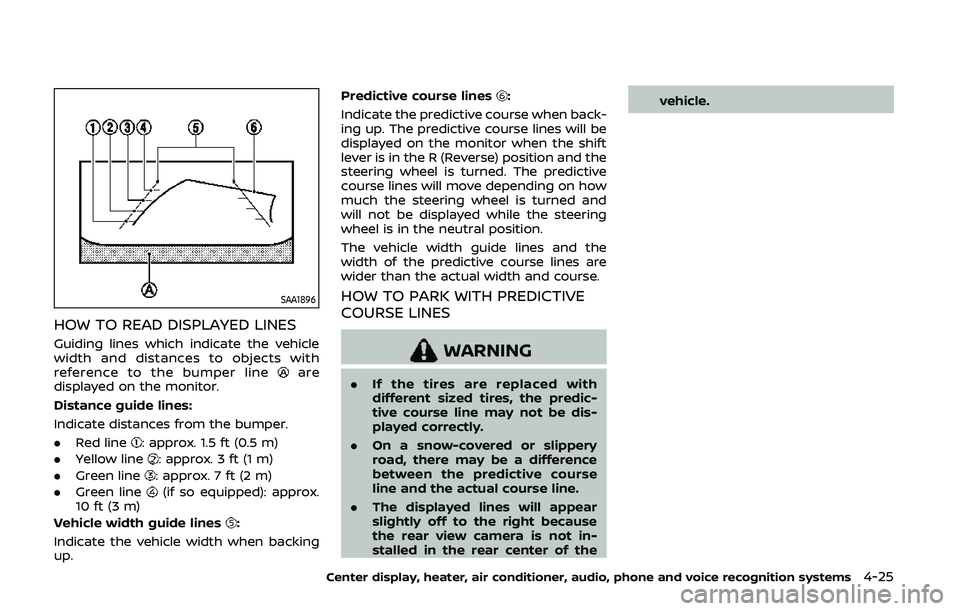
HOW TO READ DISPLAYED LINES
Guiding lines which indicate the vehicle
width and distances to objects with
reference to the bumper line
are
displayed on the monitor.
Distance guide lines:
Indicate distances from the bumper.
. Red line
: approx. 1.5 ft (0.5 m)
. Yellow line
: approx. 3 ft (1 m)
. Green line
: approx. 7 ft (2 m)
. Green line
(if so equipped): approx.
10 ft (3 m)
Vehicle width guide lines
:
Indicate the vehicle width when backing
up. Predictive course lines
:
Indicate the predictive course when back-
ing up. The predictive course lines will be
displayed on the monitor when the shift
lever is in the R (Reverse) position and the
steering wheel is turned. The predictive
course lines will move depending on how
much the steering wheel is turned and
will not be displayed while the steering
wheel is in the neutral position.
The vehicle width guide lines and the
width of the predictive course lines are
wider than the actual width and course.
HOW TO PARK WITH PREDICTIVE
COURSE LINES
WARNING
. If the tires are replaced with
different sized tires, the predic-
tive course line may not be dis-
played correctly.
. On a snow-covered or slippery
road, there may be a difference
between the predictive course
line and the actual course line.
. The displayed lines will appear
slightly off to the right because
the rear view camera is not in-
stalled in the rear center of the vehicle.
Center display, heater, air conditioner, audio, phone and voice recognition systems4-25