2020 NISSAN 370Z manual transmission
[x] Cancel search: manual transmissionPage 18 of 455

0-10Illustrated table of contents
SSI0652
1. Vehicle Dynamic Control (VDC) OFF switch(P.5-30)
2. Headlight, fog light and turn signal switch (P.2-35)
3. Meters and Gauges (combimeter) (P.2-5)
4. Triple meter (P.2-8)
5. Wiper and washer switch (P.2-33) 6. Hood release handle (P.3-16)
7. Intelligent Key port (P.5-10)
8. Paddle shifter (if so equipped) (P.5-14)
9. Steering-wheel-mounted controls (left
side)
— Menu control switch or tuning switch
(P.4-79) — BACK switch (P.4-79)
— Phone switch (if so equipped) (P.4-82,
P.4-92)
— Volume control switches (P.4-79)
— Source select switch (P.4-79)
10. Tilt steering lever (P.3-37)
11. Steering wheel — Horn (P.2-39)
— Driver supplemental air bag (P.1-31)
12. Steering-wheel-mounted controls (right side)
— Cruise control switches (P.5-22)
13. Shift lever — Automatic Transmission (AT) (P.5-12)
— Manual Transmission (MT) (P.5-17)
14. Parking brake (P.5-21)
COCKPIT
Page 26 of 455

1-4Safety — Seats, seat belts and supplemental restraint system
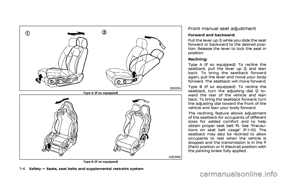
SSS0394Type A (if so equipped)
JVR0389XType B (if so equipped)
Front manual seat adjustment
Forward and backward:
Pull the lever up
while you slide the seat
forward or backward to the desired posi-
tion. Release the lever to lock the seat in
position.
Reclining:
Type A (if so equipped): To recline the
seatback, pull the lever up
and lean
back. To bring the seatback forward
again, pull the lever and move your body
forward. The seatback will move forward.
Type B (if so equipped): To recline the
seatback, turn the adjusting dial
to-
ward the rear of the vehicle and lean
back. To bring the seatback forward, turn
the adjusting dial toward the front of the
vehicle and lean your body forward.
The reclining feature allows adjustment
of the seatback for occupants of different
sizes for added comfort and to help
obtain proper seat belt fit. See “Precau-
tions on seat belt usage” (P.1-10). The
seatback may also be reclined to allow
occupants to rest when the vehicle is
stopped and the transmission is in the P
(Park) position or N (Neutral) position with
the parking brake fully applied.
Page 71 of 455

SSI0652
1. Vehicle Dynamic Control (VDC) OFF switch(P.5-30)
2. Headlight, fog light and turn signal switch (P.2-35)
3. Meters and Gauges (combimeter) (P.2-5)
4. Triple meter (P.2-8)
5. Wiper and washer switch (P.2-33) 6. Hood release handle (P.3-16)
7. Intelligent Key port (P.5-10)
8. Paddle shifter (if so equipped) (P.5-14)
9. Steering-wheel-mounted controls (left
side)
— Menu control switch or tuning switch
(P.4-79) — BACK switch (P.4-79)
— Phone switch (if so equipped) (P.4-82)
— Volume control switches (P.4-79)
— Source select switch (P.4-79)
10. Tilt steering lever (P.3-37)
11. Steering wheel — Horn (P.2-39)
— Driver supplemental air bag (P.1-31)
12. Steering-wheel-mounted controls (right side)
— Cruise control switches (P.5-22)
13. Shift lever — Automatic Transmission (AT) (P.5-12)
— Manual Transmission (MT) (P.5-17)
14. Parking brake (P.5-21)
Instruments and controls2-3
COCKPIT
Page 86 of 455

2-18Instruments and controls
For more details about the electric soft
top operation, see “Soft top (Roadster
models)” (P.3-22).
SynchroRev Match mode (S-
MODE) indicator (if so equipped)
This indicator will illuminate when the
SynchroRev Match mode (S-MODE) is
activated. (See “SynchroRev Match mode
(S-MODE) (if so equipped for Manual
Transmission models)” (P.5-18).)
Transmission position indica-
tor (if so equipped)
When the ignition switch is pushed to the
ON position, the indicator shows the
transmission position.
For AT models:
In the manual shift mode, when the
transmission does not shift to the se-
lected gear due to the transmission
protection mode, the AT position indica-
tor light will blink and a buzzer will sound.
(See “Driving the vehicle” (P.5-12).)
Turn signal/hazard indicator
lights
The light flashes when the turn signal
switch lever or hazard switch is turned on.
Vehicle Dynamic Control (VDC)
off indicator light
When the ignition switch is in the ON
position, the Vehicle Dynamic Control
(VDC) off indicator light illuminates and
then turns off.
The light comes on when the VDC off
switch is pushed to OFF. This indicates
that the VDC system and traction control
system are not operating.
AUDIBLE REMINDERS
Key reminder chime
A chime will sound if the driver side door
is opened while the ignition switch is
pushed to the ACC position or pushed
to the OFF or LOCK position with the
Intelligent Key left in the Intelligent Key
port. Make sure the ignition switch is
pushed to the OFF position, and take
the Intelligent Key with you when leaving
the vehicle.
Light reminder chime
A chime will sound when the driver side
door is opened with the light switch in the
orposition and the ignition
switch in the ACC, OFF or LOCK position.
Turn the light switch off when you leave
the vehicle.
Parking brake reminder chime
A chime will sound if the vehicle speed is
above 4 MPH (7 km/h) with the parking
brake applied. Stop the vehicle and re-
lease the parking brake.
Brake pad wear warning
The disc brake pads have audible wear
warnings. When a brake pad requires
replacement, it will make a high pitched
scraping sound when the vehicle is in
motion. This scraping sound will first
occur only when the brake pedal is
depressed. After more wear of the brake
pad the sound will always be heard even
if the brake pedal is not depressed. Have
the brakes checked as soon as possible if
the warning sound is heard.
Page 89 of 455

more details.
5. SHIFT “P” warning (Automatic
Transmission models)
This warning appears when the ignition
switch is pushed to stop the engine with
the shift lever in any position except the P
(Park) position.
If this warning appears, move the shift
lever to the P (Park) position or push the
ignition switch to the ON position.
An inside warning chime will also sound.
(See “Intelligent Key system” (P.3-6).)
6. “PUSH” warning (Automatic
Transmission models)
This warning appears when the shift lever
is moved to the P (Park) position with the
ignition switch in the ACC position after
the SHIFT “P” warning appears.
To push the ignition switch to the OFF
position, perform the following proce-
dure:
SHIFT “P” warning?(Move the shift lever
to “P”) ?PUSH warning ?(Push the
ignition switch ?ignition switch position
is turned to ON) ?PUSH warning ?
(Push the ignition switch ?ignition
switch position is turned to OFF)
7. Intelligent Key battery discharge
indicator
This indicator appears when the Intelli-
gent Key battery is running out of power.
If this indicator appears, replace the
battery with a new one. (See “Intelligent
Key battery replacement” (P.8-20).)
8. Engine start operation indicator
(Manual Transmission models)
This indicator means that the engine will
start by pushing the ignition switch with
the clutch pedal depressed.
Instruments and controls2-21
Page 91 of 455

COLD tire pressure shown on the recom-
mended COLD tire pressure shown on the
Tire and Loading Information label. (See
“Tire Pressure Monitoring System (TPMS)”
(P.5-3) and “Tire Pressure Monitoring Sys-
tem (TPMS)” (P.6-3).
7. “TIMER” indicator
This indicator appears when the set
“TIMER” indicator activates. You can set
the time for up to 6 hours. (See “Trip
computer” (P.2-25).)
8. Low outside temperature warn-
ing
This warning appears if the outside tem-
perature is below 37°F (3°C). The warning
can be set not to be displayed. (See “Trip
computer” (P.2-25).)
9. SynchroRev Match mode (S-
MODE) warning
This warning appears if a system mal-
function occurs. When the warning ap-
pears, the S-MODE function will not
operate, but the manual transmission will
operate normally and driving can be
continued. Have the system checked. It
is recommended you visit a NISSAN dealer
for this service.
10. Extended storage fuse warning
This warning may appear if the extended
storage fuse switch is not pushed in
(switched on). When this warning ap-
pears, push in (switch on) the extended
storage fuse switch to turn off the warn-
ing. For more information, see “Extended
storage fuse switch” (P.8-19).
Instruments and controls2-23
Page 154 of 455

3-28Pre-driving checks and adjustments
TROUBLESHOOTING GUIDE
If the soft top stops halfway during operation or does not operate normally, follow the procedures shown in the following table. If the
procedures in the following table do not solve the symptom, have your vehicle inspected immediately. It is recommended to visit a
NISSAN dealer for this service.
SymptomBeepPossible cause Possible solution
The OPEN side of the soft top oper-
ating switch is pushed, but the soft
top does not operate. Sounds twice
The OPEN side of the soft top operating
switch is pushed while the soft top is fully
open, or the CLOSE side of the soft top
operating switch is pushed while the soft
top is fully closed. Push the CLOSE side of the soft top operating
switch when the soft top is fully open. Push
the OPEN side of the soft top operating switch
when the soft top is fully closed.
Sounds twice The shift lever is in the R (Reverse) position. Shift the shift lever to the P (Park) or N
(Neutral) position (automatic transmission
models only), or shift the shift lever to the N
(Neutral) position (manual transmission mod-
els only), and then operate the soft top.
Sounds twice The trunk lid is opened. Fully close the trunk lid.
Does not sound The battery voltage is low.
Start the engine again and operate the soft
top.
Does not sound The operation stops to protect the system. Wait for approximately 5 minutes.
The soft top stops halfway during
operation. Sounds twice
Objects are trapped in the moving structure
of the soft top. Check that an object is not trapped inside the
rear parcel shelf, side flap and soft top. After
the check, place the ignition switch in the OFF
position, start the engine again and then
operate the soft top.
Sounds twice The battery voltage is low. Start the engine again and operate the soft
top.
When the vehicle is being driven, the
beep sounds. Sounds con-
tinuously The soft top is partially opened. Immediately park the vehicle in a safe location
and fully open or fully close the soft top.
Page 194 of 455

4-26Center display, heater, air conditioner, audio, phone and voice recognition systems
SAA1897
1. Visually check that the parking spaceis safe before parking your vehicle.
2. The rear view of the vehicle is dis- played on the screen
when the shift
lever is moved to the R (Reverse)
position.
SAA1898
3. Slowly back up the vehicle adjusting the steering wheel so that the pre-
dictive course lines
enter the park-
ing space.
4. Maneuver the steering wheel to make the vehicle width guide lines
parallel
to the parking spacewhile referring
to the predictive course lines. 5. When the vehicle is parked in the
space completely, move the shift lever
to the P (Park) position (Automatic
Transmission models) or in an appro-
priate gear (Manual Transmission
models) and apply the parking brake.
DIFFERENCE BETWEEN PREDICTIVE
AND ACTUAL DISTANCES
The displayed guide lines and their loca-
tions on the ground are for approximate
reference only. Objects on uphill or down-
hill surfaces or projecting objects will be
actually located at distances different
from those displayed in the monitor
relative to the guide lines (refer to illustra-
tions). When in doubt, turn around and
view the objects as you are backing up, or
park and exit the vehicle to view the
positioning of objects behind the vehicle.