2020 MITSUBISHI ECLIPSE CROSS connect
[x] Cancel search: connectPage 266 of 427

Warning lights
Features and controls 5-185
5
N00520501856
This indicator is a part
of the onboard diag-
nostic (OBD) system which monitors the emissions, engine control system or continu-ously variable transmission (CVT) control system. If a problem is detected in one of these systems, this indicator illuminates orflashes. When the igniti
on switch is turned to
the “ON” position or the operation mode is put in ON, this indicator normally comes onand goes off after the engine has started. This indicator will come on if the fuel tank filler cap is not properly tightened. If this
indicator comes on and stays on after refuel- ing, stop the engine and check that the cap is properly tightened. (Turn the cap clockwise until you hear clicking sounds.)If this indicator does not go off after several seconds or lights up while driving, have the system checked as soon as possible at anauthorized Mitsubishi Motors dealer or a repair facility of your choice.
CAUTION When the warning light remains on or does not come on, there is the possibility that the parking brake cannot be operated or released. Immediately contact the nearest authorized Mitsubishi Motors dealer. Whenthe warning light comes on during driving, immediately stop the vehicle in a safe place, and contact an authorized Mitsubishi Motorsdealer. If you inevitably have to park, park the vehicle on level and stable ground, shift the selector lever in “P” (PARK) positionand place chocks or blocks.
Engine malfunction indicator (“SERVICE ENGINE SOON” or “Check engine light”)
CAUTION Driving for a long time with the engine mal- function indicator on may cause more dam- age to the emission control system. This could also affect fuel economy and drivabil-ity. If this indicator does not come on when the ignition switch is turned to the “ON” posi- tion or the operation mode is put in ON, have the system checked at an authorizedMitsubishi Motors dealer or a repair facility of your choice.
If the engine malfunction indicator comes on while the engine is running, avoid driving at high speeds. During vehicle operation with the indicator on, the vehicle may not accelerate when youdepress the accelerator pedal. When the vehicle is stationary with the indi- cator on, you must depress the brake pedalmore firmly than usual since the engine idling speed is higher than usual and a vehi- cle with continuously variable transmission(CVT) has a stronger tendency to creep for- ward.NOTE
Do not disconnect the battery cable when the engine malfunction indicator (“SERVICEENGINE SOON” or “Check engine light”) is on. The engine electronic control module storescritical OBD information (especially exhaust emission data), which may be lost if the bat- tery cable is disconnected while the enginemalfunction indicator is on. This will make it difficult to diagnose the cause of future prob- lems.CAUTION
BK0277700US.book
185 ページ 2019年3月8日 金曜日 午前9時23分
Page 270 of 427
Head Up Display (HUD) (if so equipped)
Features and controls 5-189
5
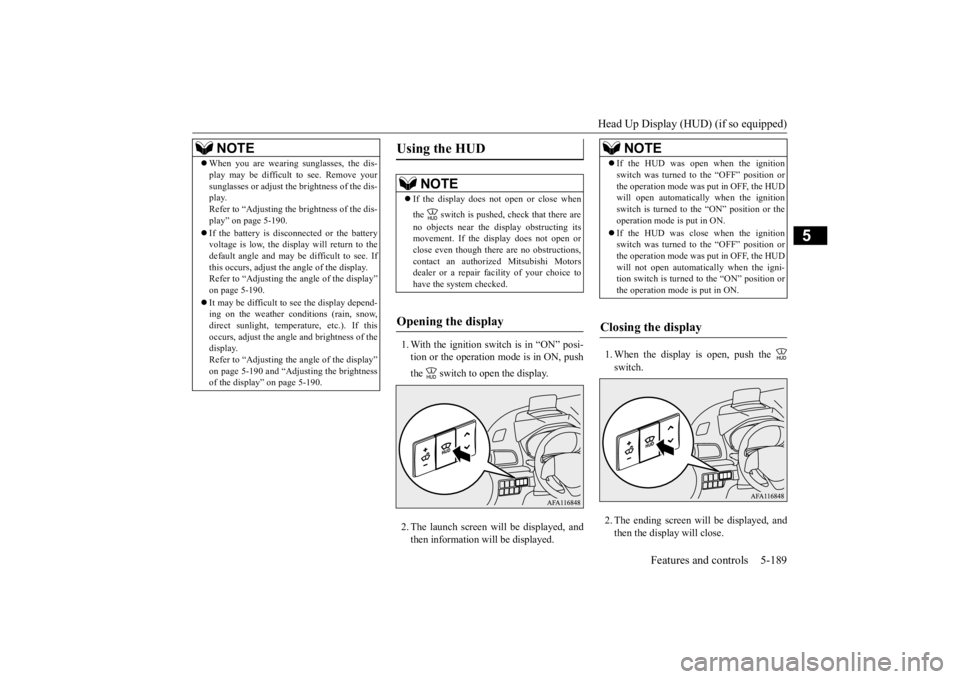
1. With the ignition switch is in “ON” posi- tion or the operation mode is in ON, push the switch to open the display. 2. The launch screen will be displayed, and then information will be displayed.
1. When the display is open, push the switch. 2. The ending screen will be displayed, and then the display will close.
NOTE
When you are wearing sunglasses, the dis- play may be difficult to see. Remove your sunglasses or adjust the brightness of the dis- play. Refer to “Adjusting the brightness of the dis-play” on page 5-190. If the battery is disconnected or the battery voltage is low, the display will return to the default angle and may be difficult to see. If this occurs, adjust the angle of the display.Refer to “Adjusting the angle of the display” on page 5-190. It may be difficult to see the display depend- ing on the weather conditions (rain, snow, direct sunlight, temperature, etc.). If thisoccurs, adjust the angle and brightness of the display. Refer to “Adjusting the angle of the display”on page 5-190 and “Adjusting the brightness of the display” on page 5-190.
Using the HUD
NOTE
If the display does not open or close when the switch is pushed, check that there are no objects near the display obstructing its movement. If the display does not open or close even though there are no obstructions, contact an authorized Mitsubishi Motorsdealer or a repair facility of your choice to have the system checked.
Opening the display
NOTE
If the HUD was open when the ignition switch was turned to the “OFF” position or the operation mode was put in OFF, the HUD will open automatically when the ignition switch is turned to the “ON” position or theoperation mode is put in ON. If the HUD was close when the ignition switch was turned to the “OFF” position or the operation mode was put in OFF, the HUD will not open automatically when the igni-tion switch is turned to the “ON” position or the operation mode is put in ON.
Closing the display
BK0277700US.book
189 ページ 2019年3月8日 金曜日 午前9時23分
Page 281 of 427

Hazard warning flasher switch 5-200 Features and controls
5
tion (1). It will return to the neutral position when you let go. Use the full position (2) when making a normal turn. The lever will return to the neutral position when the turn iscomplete. There may be times when the lever does not return to the neutral position. This usually happens when the steering wheel isturned only slightly. You can easily return the lever by hand. Also, when you move the lever to (1) slightlythen release it, the turn signal lights and theindicator light in the instrument cluster will flash three times.
N00522701344
If you press the flasher switch, the front and rear turn signals will flash intermittently, and so will the hazard warn
ing lights. This is an
emergency warning system and should not beused when the vehicle is in motion, except foremergencies. If you need to leave your vehicle, the flashers will keep working after the ignition switch isremoved or the operation mode is put in OFF.
NOTE
A light in the instrument panel flashes to show when the front and rear turn signal lights are working properly. If this light flashes faster than usual, check for a burned out turn signal light bulb or mal-functioning connection in the signal. If the panel light does not come on when the lever is moved, check for a blown fuse or aburned out bulb in the panel. Have the system inspected by your autho- rized Mitsubishi Motors dealer or a repairfacility of your choice. It is possible to modify functions as follows: • Deactivate the turn signal light 3-flash function for lane changes. • Adjust the time required to operate the lever for the 3-flash function. See your authorized Mitsubishi Motors dealer for details.For vehicles equipped with the Smartphone Link Display Audio, adjustments can be made using screen operations. For furtherdetails, refer to the separate owner’s manual. It is possible to change the tone of a sound- ing buzzer as the turn signal lights flash. Refer to “Changing the turn signal sound” on page 5-161.
Hazard warning flasher switch
NOTE
If the flashers are used for several hours, the battery will run down. This could make it difficult or impossible to restart your vehicle.
BK0277700US.book
200 ページ 2019年3月8日 金曜日 午前9時23分
Page 290 of 427

Horn switch
Features and controls 5-209
5
N00523801195
To honk the horn, press around the “ ” mark on the steering wheel.
N00566701269
You can connect your USB memory device or iPod
* to play music files stored in the USB
memory device or iPod. * : “iPod” is a registered trademark of Apple Inc. in the United States and other countries. The USB input terminal (A) is located in the indicated position. This section explains how to connect and remove a USB memory device or iPod.
N00566801244
1. Park your vehicle in a safe place and turn the ignition switch to the “OFF” position or put the operation mode in OFF.2. Connect a commercially available USB connector cable (B) to the USB memory device (A). 3. Connect the USB connector cable to the USB input terminal.
Horn switch
USB input terminal
Type 1 Type 2
How to connect a USB memory device
NOTE
Do not connect the USB memory device to the USB input terminal directly.The USB memory device may be damaged.
BK0277700US.book
209 ページ 2019年3月8日 金曜日 午前9時23分
Page 291 of 427

Sun visors 5-210 Features and controls
5
4. To remove the USB connector cable, turn the ignition switch to the “OFF” position or put the operation mode in OFF first and perform the installation steps in reverse.
N00566901274
1. Park your vehicle in a safe place and turnthe ignition switch to the “OFF” position or put the operation mode in OFF. 2. Connect the connector cable to the iPod. 3. Connect the connector cable to the USB input terminal. 4. To remove the connector cable, turn the ignition switch to the “OFF” position orput the operation mode in OFF first and perform the installation steps in reverse.
N00567001126
For details, please refer to the separatedowner’s manual for “Smartphone Link Dis- play Audio” or the “DISPLAY AUDIO”.
N00524601419
Pull the sun visor downward (1) to reducefront glare while driving. To reduce sideglare, turn the visor to the side (2).
How to connect an iPod
NOTE
Use a genuine connector cable from Apple Inc.
Types of connectable devices and supported file specifica- tions
Sun visors
NOTE
Pull the sun visor sideways to eliminate side glare farther to the rear. (if so equipped)
BK0277700US.book
210 ページ 2019年3月8日 金曜日 午前9時23分
Page 322 of 427

Trailer towing
Driving safety 6-13
6
A safety chain must always be used between the towing vehicle and the trailer. Leave suf- ficient slack in the chain for turns. The chain should cross under the trailer tongue to pre-vent the tongue from dropping to the ground in case it becomes damaged or separated. For correct safety chain procedures, consultyour authorized Mitsubishi Motors dealer.
Your vehicle will need service more often when you’re towing a trailer. Refer to “WAR- RANTY AND MAINTENANCE MAN- UAL”. Especially important in traileroperation are automatic transaxle fluid, engine oil, rear axle oil, belt, cooling system and brake system. Each of these is covered inthis manual.For details, please refer to the “Vehicle care and maintenance” section. Check periodically to see that all hitch nutsand bolts are tight. Mitsubishi Motors recommends that any trailer having a total weight of 1,250 lb (567 kg) or more be equipped with its own electric or surge-type brakes. If you choose electric brakes, be sure they are electrically actuated. Do not attempt to tap into your vehicle’s hydraulic system. No mat- ter how successful it may seem, any attemptto attach trailer brakes to your vehicle’s hydraulic system will lower braking effec- tiveness and create a potential hazard.
Trailer lights and equipment must comply with federal, state, and local regulations.Check with your local recreational vehicle dealer for the requirements in your area, and use only equipment designed for your vehi-cle. Since lighting and wiring vary by trailer type and brand, you should have a qualified tech- nician install a suitable connector between the vehicle and the trailer. Improper equipment orinstallation can cause damage to your vehi- cle’s electrical system and affect your vehicle warranty. Many states and Canadian provinces require special outside mirrors when towing a trailer.Even if not required, you should install spe- cial mirrors if you cannot clearly see behind you, or if the trailer creates a blind spot. Ask your trailer sales or rental agency if any other items are recommended or required for your towing situation.
NOTE
Mitsubishi Motors recommends that sway control be used when
ever you are towing, to
improve towing stability. For further information, please contact your authorized Mitsubishi Motors dealer.
Safety chains
CAUTION Never tow a trailer without using a safety chain securely attached to both the trailer and the vehicle. If the coupling unit or hitch ball experiences a problem, the trailer may separate from your vehicle.
Maintenance when trailer tow- ing Trailer brakes
Trailer lights Additional trailer equipment
BK0277700US.bo
ok 13 ページ 2019年3月8日 金曜日 午前9時23分
Page 354 of 427

Jump-starting the engine For emergencies 8-3
8
4. Set the parking brake firmly on the other vehicle. Put the automatic transaxle in “P” (PARK) or the manual transaxle in “N” (Neutral).5. Turn the ignition switch (the engine switch) on each vehicle to the “LOCK” or “OFF” position. 6. Make sure your battery electrolyte is at the proper level. (Refer to “Battery” on page 9-10.) 7. Connect one end of one jumper cable to the positive (+) terminal of the dis- charged battery (A), and then connect the other end to the positive (+) terminal of the booster battery (B).
8. Connect one end of the other jumper cable
to the negative (-) terminal of the booster battery (B), and then connect the other end to the designated ground location of the vehicle with the discharged battery (A) at the point farthest from thebattery. 9. Start the engine in the vehicle providing the boost. Let the engine idle a few min- utes, then start the engine in the vehicle with the discharged battery.
10. After the engine is started, disconnect the
cables in the reverse order from the way you connected them.
NOTE
Turn off all lights, heater, and other electrical loads. This will avoid sparks and help save both batteries.WA R N I N G If the electrolyte fluid is not visible, or looks frozen, DO NOT ATTEMPT JUMP STARTING!! The battery might split open or explode ifthe temperature is below the freezing point or if it is not filled to the proper level.
WA R N I N G Make sure that the jumper cables and your clothing are clear of the cooling fans and drive belts. Entanglement with the fans or belts can cause serious personalinjury.NOTE
Open the terminal cover before connecting the jumper cable to the positive terminal ofthe battery. (Refer to “Battery” on page 9-10.) Use the proper cables suitable for the battery size. Otherwise heat damage to the cables couldresult.
WA R N I N G Be sure to follow the proper order when connecting the batteries, of:
Make sure that the connection is made to the correct designated location (as shown in the illustration) properly. If the connection is directly made to the negative(-) terminal of the battery, the flammable gases from inside the battery might catch fire and explode, causing personal injury. When connecting the jumper cable, do not connect the positive (+) cable to the nega-tive (-) terminal. Sparks can make the bat- tery explode.
BK0277700US.bo
ok 3 ページ 2019年3月8日 金曜日 午前9時23分
Page 368 of 427

Engine hood
Vehicle care and maintenance 9-3
9
destroy the emission-control effectiveness of the converter. Normally, the catalytic converter does not require maintenance. However, it is important to keep the engine properly tuned for the con-verter to continue to work properly. To reduce the possibility of catalytic con- verter damage: Use UNLEADED GASOLINE ONLY of the type recommended in “Fuel selection” on page 3-2.
Do not drive with an extremely low fuel level. Running out of gas could damage the catalytic converter. Do not try to start the engine by pushing or towing the vehicle. If the battery is weak or run down, use jumper cables to properly start the engine.Refer to “Jump-starting the engine” on page 8-2. Do not idle the engine with any spark plug wires disconnected or removed, such aswhen performing diagnostic tests. Do not idle the engine for a long time if it is idling roughly or otherwise obviouslymalfunctioning. To prevent damage to the catalytic con- verter from unburned gas, do not race theengine when turning off the ignition switch. Stop driving the vehicle if you think the performance is noticeably low, or the engine has a malfunction such as with the ignition, etc. If you
are not able to stop
driving immediately, slow down and drive for only a short time. Have your vehicle checked at an authorized MitsubishiMotors dealer or a repair facility of your choice as soon as possible.
In unusual situations involving major engine problems, a burning odor may indicate severe and abnormal catalytic converter overheating. If this occurs, stopin a safe place, shut the engine off and let the vehicle cool. Once the engine is cool, immediately take your vehicle to anauthorized Mitsubishi Motors dealer or a repair facility of your choice for service.
N00937501650
Use the engine hood release lever (located under the instrument panel near the driver’s door) to unlock the engine hood. Pull the lever toward you to release the engine hood latch.
CAUTION Damage to the catalytic converter can result if your vehicle is not kept in proper operating condition. If the engine malfunctions or mis-fires, or if your vehicle performance suffers, have it serviced promptly. Running your vehicle when it is overheated may result indamage to the converter and vehicle.WA R N I N G Do not park or run your vehicle in areas where combustible materials such as drygrass or leaves can come in contact with a hot exhaust, since a fire could occur. Do not put undercoat paint on the cata- lytic converter.
Engine hood To open
BK0277700US.bo
ok 3 ページ 2019年3月8日 金曜日 午前9時23分