2020 MERCEDES-BENZ GLS SUV load capacity
[x] Cancel search: load capacityPage 298 of 549
%
The maximum articulation angle depends on
th e length of the trailer. This is calculated by
th e sy stem bydriving theve hicle forw ards,
including cornering. Before the length of the
trailer has been calculated, the maximum
articulation angle is appr oximately 23°. The
longer the trailer is, the higher the maximum
articulation angle (max. appr oximately 60°).
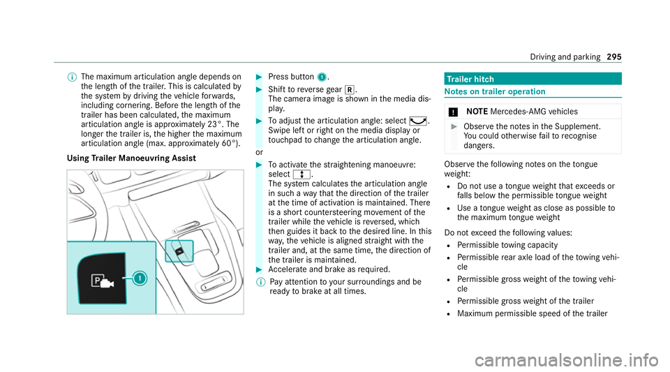
Using Trailer Manoeuvring Assist #
Press button 1. #
Shift toreve rsege ar k.
The camera image is shown in the media dis‐
pla y. #
Toadjust the articulation angle: select ¸.
Swipe left or right on the media display or
to uchpad tochange the articulation angle.
or #
Toactivate thest ra ightening manoeuvre:
select º.
The sy stem calculates the articulation angle
in such a wayth at the direction of the trailer
at the time of activation is maintained. There
is a short counter steering mo vement of the
trailer while theve hicle is reve rsed, which
th en guides it back tothe desired line. In this
wa y,theve hicle is aligned stra ight with the
trailer and, at the same time, the direction of
th e trailer is maintained. #
Accelerate and brake as requ ired.
% Pay attention toyour sur roundings and be
re ady tobrake at all times. Tr
ailer hitch Note
s on trailer operation *
NO
TEMercedes-AMG vehicles #
Obser vethe no tes in the Supplement.
Yo u could otherwise failto recognise
dangers. Obser
vethefo llowing no tes on theto ngue
we ight:
R Do not use a tongue weight that exceeds or
fa lls below the permissible tongue weight
R Use a tongue weight as close as possible to
th e maximum tongue weight
Do not exceed thefo llowing values:
R Perm issible towing capacity
R Perm issible rear axle load of theto wing vehi‐
cle
R Perm issible gross weight of theto wing vehi‐
cle
R Perm issible grossweight of the trailer
R Maximum permissible speed of the trailer Driving and parking
295
Page 303 of 549
*
NO
TEDama gewhen uncoupling in a
st ate of overrun Uncou
pling in a state of overru n can dama ge
th eve hicle. #
Do not uncouple trailers with an
engaged overrun brake. &
WARNING Risk of becoming trapped
when disconnecting the trailer cable
Ve hicles with le vel control sy stem: The
ve hicle may lo wer when the trailer cable is
disconnected.
This could result in you or other people
becoming trapped if your or their limbs are
between theve hicle body and the tyres or
underneath theve hicle. #
Make sure that nobody is unde rneath
th eve hicle or in the immediate vicinity
of the wheel ar ches when you discon‐
nect the trailer cable. *
NO
TEDama getothere ar bumper from
ins talling adap ter cables or adapte r plugs The
following parts could be damaged when
swiveling the ball neck fully electrically:
R Bumper
R Adapter cable
R Adapter plug #
Alw aysre mo vethe adap ter cable or
adapte r plug before swive lingthe ball
neck fully electrically. #
Secure the trailer against rolling away. #
Disconnect the electrical connection
between theve hicle and the trailer. #
Uncouple the trailer. #
Place the co ver cap on the ball head. Bicycle
rackfunction &
WARNING Risk of an accident when
using the bicycle rack incor rectly
The bicycle rack may become de tach ed from
th eve hicle in thefo llowing cases:
R the permissible load capacity of the
trailer hitch is exceeded.
R the bicycle rack is used incor rectl y.
R the bicycle rack is secured tothe ball
neck beneath the ball head.
Obser vethefo llowing foryo ur ow n sa fety
and that of other road users:
R always adhere tothe permissible load
capacity of the trailer hitch.
R only use the bicycle rack totranspo rt
bicycles.
R always mount the bicycle rack properly by
attaching tothe ball head and the ball
neck guide pin, if possible. 300
Driving and parking
Page 304 of 549
R
when transporting four bic ycles, alw ays
use bic ycle rack s which ha veadditional
suppo rton the ball neck guide pin.
R only use bicycle rack s appr ovedby
Mercedes-Benz.
R always obser vethe bicycle rack operating
instructions. *
NO
TEDama geto, or crac kson, the
trailer hitch due tounsuitable bic ycle
ra ck s or bicycle rack s being used incor‐
re ctly #
use only bicycle rack s appr ovedby
Mercedes-Benz. Tr
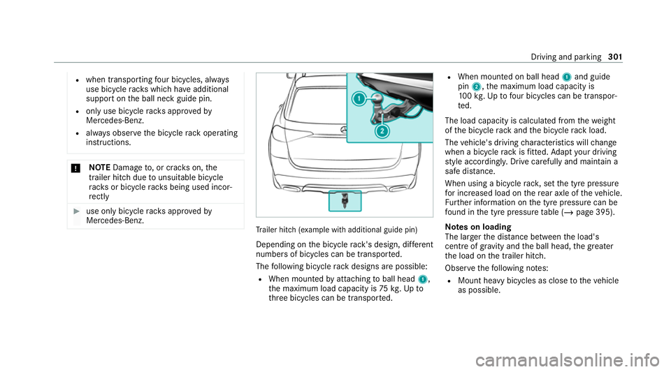
ailer hit ch(examp le with additional guide pin)
Depending on the bicycle rack 's design, dif fere nt
numbe rsof bicycles can be transpor ted.
The following bicycle rack designs are possible:
R When mounted byattaching toball head 1,
th e maximum load capacity is 75kg.Up to
th re e bicycles can be transpor ted. R
When mounted on ball head 1and guide
pin 2, the maximum load capacity is
10 0kg .Up tofour bic ycles can be transpor‐
te d.
The load capacity is calculated from thewe ight
of the bicycle rack and the bicycle rack load.
The vehicle's driving characteristics will change
when a bicycle rack isfitted. Adapt your driving
st yle accordingly. Drive carefully and maintain a
safe dis tance.
When using a bicycle rack , set the tyre pressure
fo r increased load on there ar axle of theve hicle.
Fu rther information on the tyre pressure can be
fo und in the tyre pressure table (/ page 395).
Note s on loading
The larger the dis tance between the load's
cent reof gr avity and the ball head, the greater
th e load on the trailer hitch.
Obser vethefo llowing no tes:
R Mount heavy bicycles as close totheve hicle
as possible. Driving and parking
301
Page 401 of 549
When
replacing tyres, make sure tofit the
cor rect:
R Designation
R Manufactu rer
R Type &
WARNING Risk of inju rythro ugh exceed‐
ing the specified tyre load-bearing capa‐
city or the permissible speed rating
Exceeding the load-bearing capacity of the
tyres can lead totyre dama geand could
cause the tyres toexplode. #
Therefore, only use tyre types and sizes
appr ovedfo ryo ur vehicle model. #
Obser vethe tyre load-bearing capacity
ra ting and speed rating requ iredfor
yo ur vehicle. *
NO
TEVehicle and tyre damage thro ugh
tyre types and sizes that ha venot been
appr oved Fo
r saf etyre asons, on lyuse tyres, wheels
and accessories which ha vebeen specially
appr ovedby Mercedes-Benz foryo ur vehicle.
These tyres are specially adap tedto the con‐
trol sy stems, such as ABS, ESP ®
and
4MATIC, and mar ked as follo ws:
R MO = Mercedes-Benz Original
R MOE = Mercedes-Benz Original Extended
(run-flat tyres only for cer tain wheels)
R MO1 = Mercedes-Benz Original (only cer‐
tain AMG tyres)
Cer tain characteristics, such as handling,
ve hicle noise emissions, consum ption, etc.
may otherwise be adversely af fected. Fur‐
th ermore, other tyre sizes could result in the
tyres rubbing against the body and axle com‐
ponents when loaded. This could result in
damage tothe tyre or theve hicle. Only use tyres, wheels and accessories
that
ha ve been checked and recommended by
Mercedes-Benz. *
NO
TERisk todriving saf ety from retrea‐
ded tyres Re
treaded tyres are nei ther tested nor rec‐
ommended byMercedes-Benz, since pr evi‐
ous damage cannot alw ays be de tected on
re treaded tyres.
Fo rth is reason driving saf ety cannot be guar‐
anteed. #
Do not use used tyres if you ha veno
information about their pr evious usage. *
NO
TEPossible damage towheels or
tyres when driving over obs tacles Large wheels ha
vea lo wer tyre section width.
The lo werth e tyre section width, the greater
is therisk of damage towheels or tyres when
driving over obs tacles. 398
Wheels and tyres
Page 404 of 549
R
rear wheels wear more in the cent reofthe
tyre
Do not drive wi thtyres that ha vetoo little tread
dep th. This significantly reduces traction on wet
ro ads (aquaplaning).
On vehicles with the same front and rear wheel
size, you can inter change the wheels every
5000 to10,000 km, depending on thewe ar.
Ensure the direction of rotation is maintained for
th e wheels.
Obser vethe instructions and saf ety no tes on
"Changing a wheel" when doing so
(/ page 402). Note
s onstoring wheels When
storing wheels, obser vethefo llowing
no tes:
R Afterre moving wheels, store them in a cool,
dry and preferably dark place.
R Protect the tyres from conta ct withoil,
grease or fuel. Overview of
the ty re-change tool kit Apart from some countr
y-specific variants, vehi‐
cles are not equipped with a tyre-change tool kit.
Fo r more information on which tools are
re qu ired and appr ovedto per form a wheel
ch ange on your vehicle, consult a qualified spe‐
cialist workshop.
Re quired tyre-changing tools may include, for
ex ample:
R Jack
R Chock
R Wheel wrench
% The jack weighs appr oximately 3.4 kg.
The maximum load capacity of the jack can
be found on thest icke r af fixe dto the jac k.
The jack is maintenance-free. If there is a
malfunction, please conta ct aqualified spe‐
cialist workshop.
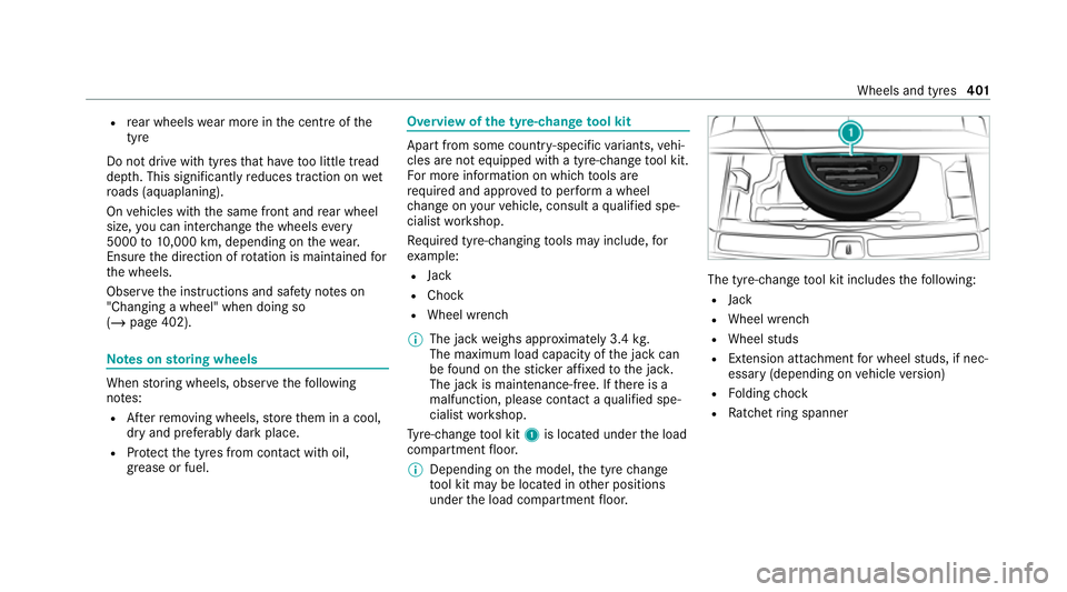
Ty re-change tool kit 1is located under the load
compartment floor.
% Depending on the model, the tyre change
to ol kit may be located in other positions
under the load compartment floor. The tyre-change
tool kit includes thefo llowing:
R Jack
R Wheel wrench
R Wheel studs
R Extension attachment for wheel studs, if nec‐
essary (depending on vehicle version)
R Folding chock
R Ratchet ring spanner Wheels and tyres
401
Page 435 of 549
Maximum
tongue weight and load capacity *
NO
TEDama gecaused bythe trailer
coming loose If
th eto ngue weight used is too lo w,the
trailer may come loose. #
The tongue weight must not be below
50 kg. #
Use a tongue weight that is as close as
possible tothe maximum permissible
to ngue weight. *
NO
TEDama gecaused bythe bicycle
ra ck coming loose When using a bicycle
rack , bo th th e maximal
to ngue weight and the maximal load capacity
should be obser ved. #
Do not exceed the permissible load
capacity. Yo
u will find vehicle-specific weight information
in theve hicle documents. Obser
vethe additional no tes on load capacity
(/ page 300).
To ngue weight Model
Maximumtongue
we ight
All models 140kg Mercedes‑Maybac
hMaximum tongue
we ight
All models 140kg Missing
values werenot available at the time of
going topress.
Load capacity Model
Maximum load
All models Mercedes‑Maybac
hMaximum load
Mercedes-Mayba ch
GLS 600 4MATIC Pe
rm issible rear axle load (trailer operation) Model
Axle load
GLS 450
4MATIC 19
20 kg
GLS 580
4MATIC 19
00 kg
All other
models 19
30 kg Mercedes‑M
ay
bach Axle load
Mercedes-
Maybach
GLS 600
4MATIC 19
00 kg 432
Tech nical da ta
Page 512 of 549
Au
tomatic car wash mode
Ac tivating.............................................. 366
Au tomatic distance control
see Active Dis tance Assi stDISTRONIC
Au tomatic driving lights ...........................157
Au tomatic engine start (ECO start/
sto p function)............................................ 197
Au tomatic engine stop (ECO start/
sto p function)............................................ 197
Au tomatic front passen ger front air‐
bag deacti vation sy stem
see Automatic front passenger front
airbag shutoff
Au tomatic front passen ger front air‐
bag shu toff
Fu nction of the automatic front
passenger front airbag deactivation
sy stem..................................................... 48
PA SSENGER AIR BAG indicator lamp....... 50
Au tomatic measures af ter an accident..... 54
Au tomatic mir rorfo lding function
Ac tivating/deactivating......................... 172Au
tomatic seat adjustment
Setting................................................... 12 0
Au tomatic transmission
DIRECT SELECT le ver............................ 204
Drive program displa y........................... 203
Drive programs...................................... 201
DY NA MIC SELECT switch...................... 201
Engaging drive position......................... 206
Engaging neutral................................... 205
Engaging park position.......................... 206
Engaging reve rsege ar........................... 205
Kickdown............................................. .208
Manual gear changing.......................... .207
St eering wheel gearshift paddles.......... 207
Tr ansmission position displa y................ 204
Tr ansmission position s.......................... 204
Axle load Perm issible............................................ 41 5
Tr ailer operation.................................... 432 B
Bag hook .................................................... 14 4
Ball ne ck
Extending/r etra cting............................ .296 Extending/r
etra cting (MBUX multi‐
media sy stem)....................................... 297
BA S (Brake Assist Sy stem)....................... 227
Battery Key.......................................................... 80
Re mo tecontrol (s tationary heater)........ 182
Battery see Battery (vehicle)
Battery (vehicle) Charging................................................ 384
Charging (Remo teOnline)..................... 189
No tes....................................................3 80
No tes (s tarting assis tance and
ch arging)............................................... 382
Re placing.............................................. 385
St arting assis tance................................ 384
Belt see Seat belt
Bic ycle rack
Load capacity........................................ 432
Tr ailer operation.................................... 300
Blind Spot Assist Activating/deactivating......................... 259 Index
509
Page 539 of 549
Fa
stening points (trailer hitch)............... 431
Information............................................ 413
Mounting dimensions (trailer hitch)....... 431
No tes (trailer hitch)............................... 430
Overhang dimension (trailer hitch)........4 31
Ra dio operating permits.........................4 15
To ngue weight...................................... .432
To wing capacity (trailer operation )........ 431
Te lephone
Connecting a mobile phone (Passk ey)... 333
Connecting a mobile phone (Secure
Simple Pairing)...................................... 333
Fu nctions in thete lephone men u.......... 333
No tes....................................................3 30
Operating modes................................... 332
Te lephone menu overvie w..................... 332
Wi reless charging (mobile phone in
th ere ar)............................................... .153
Wi reless charging (mobile phone).......... 15 3
Te lephony operating modes
Blue tooth ®
Te lephony........................... .332
Making calls in theve hicle....................3 32
Te mp erature
Setting theve hicle interior temp era‐
ture........................................................ 174Themes
Fastening.............................................. 320
Third row of seats
Fo lding back the backrest on the
th ird row of seats.................................. 14 0
Fo lding the backrest on theth ird row
of seats forw ards................................... 13 9
Getting in/out........................................ 11 2
Through-loading feature
see Seat
see Third rowof seats
Ti e-d owney es ............................................ 14 3
TIREFIT kit Declaration of conformity........................ 31
St orage location.................................... 376
Using.....................................................3 76
To ll sy stem
Wi ndsc reen............................................ 173
To ngue weight .......................................... .432
To ol
see Vehicle tool kit
To pTe ther.................................................... 68 To
uch Control
On-board computer............................... 306
Operating.............................................. .313
To uchpad
Operating.............................................. .313
To uchscreen (media display)
Operating.............................................. .313
To w- aw ay protection
Fu nction................................................ 103
Priming/deactivating.............................1 03
To w- bar sy stem........................................ .302
To w- starting............................................... 390
To wing away.............................................. 386
To wing eye
Ins talling............................................... .389
St orage location.................................... 389
To wing me thods ........................................ 385
Tr af fic information
Swit ching on the display....................... 329
Tr af fic Sign Assist
Fu nction/no tes..................................... 255
Setting................................................... 256 536
Index