2020 MERCEDES-BENZ GLS SUV warning light
[x] Cancel search: warning lightPage 275 of 549
Ve
hicle
le vel Ve
hicles
without Off-
ro ad pac kage Ve
hicles with
Off-road pack‐
age
Spor tA pprox.
-15 mm App
rox.
-15 mm
Spo rt+A pprox.
-25 mm App
rox.
-25 mm Fu
nction of ROAD SUR FACE SCAN
% This function is not available in all countries.
The ROAD SUR FACE SCAN function monitors the
ro ad in front of your vehicle using a multifunc‐
tion camera (/ page 224).ROAD SUR FACE
SCAN de tects une venness in thero ad sur face,
e.g. bu mps, before theve hicle drives overth em.
Chassis mo vements are reduced and driving
comfort is increased.
RO AD SUR FACE SCAN is automatically activated
if th efo llowing conditions are me t:
R Drive prog ram A orN is selected.
R The vehicle is set tothe normal le vel. R
You are driving at a speed between 7 km/h
and 180 km/h.
Sy stem limits
RO AD SUR FACE SCAN can be impaired in the
fo llowing situations or can stop functioning:
R Ifth e car riag ewa y is insuf ficiently lit, e.g. at
night.
R In sno w,rain, fog, heavy spr ay, if there is
gl are, in direct sunlight or in great lyvarying
light conditions.
R Ifth e windscreen in the area of multifunction
camera is dirty, mis ted up, damaged or cov‐
ered.
R Ifth ero ad sur face has no optic stru cture or
re flects light.
R Ifyo u are driving too close totheve hicle in
front.
R If sections of thero ute ha veave ry small
ra dius of cur vature.
R During ab rupt driving manoeuvres, e.g. heavy
braking or sudden acceleration. Obser
vethe no tes on cleaning the multifunction
camera (/ page 369).
Fu nction of reco very mode &
WARNING Risk of inju rydue totheve hi‐
cle moving up and down
During reco very mode, theve hicle mo ves up
and down and can cause injuries. #
When activating reco very mode, make
cer tain that no one is in the vicinity of
th eve hicle. *
NO
TERisk of dama gedue totheve hicle
moving up and down When free driving mode is activated,
the
ve hicle mo ves up and down. Vehicle parts
may be damaged if the underbody bottoms
out. #
Make sure that there is suf ficient
ground clearance when rocking free
mode is activated. 272
Driving and pa rking
Page 277 of 549
&
WARNING Risk of becoming trapped
due totheve hicle lo wering
Ve hicles with AIRMATIC or le vel control:
when you unload luggage or lea vetheve hi‐
cle, theve hicle firs trises slightly and then
re turns tothe set le vel shortly af terw ards.
Yo u or an yone else in the vicinity of the
wheel ar ches or the underbody could thus
become trapped.
The vehicle can also be lo wered af ter being
loc ked. #
When leaving theve hicle, make sure
th at nobody is in the vicinity of the
wheel ar ches or the underbody. Re
quirements:
R The vehicle has been star ted.
R Vehicles without Off-road pac kage: the
ve hicle is being driven no fasterthan
65 km/h.
R Vehicles with Off-road pac kage:
- Off-road le vel +1: theve hicle is not mov‐
ing fast erthan 100 km/h. -
Off-road le vel +2: theve hicle is not mov‐
ing fast erthan 65 km/h.
- Off- road le vel +3: theve hicle is not mov‐
ing fast erthan 20 km/h.
Ra ising theve hicle (vehicles without Off-
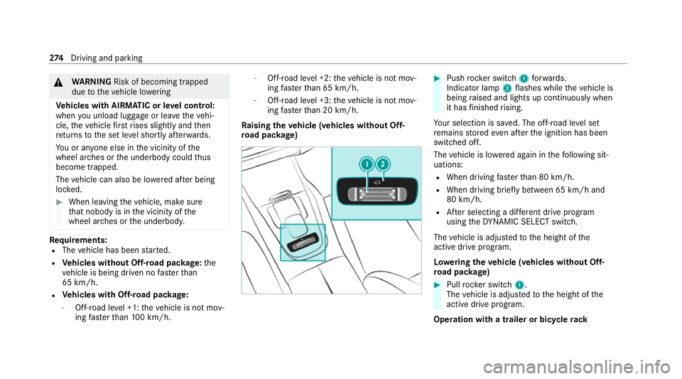
ro ad pac kage) #
Push rocker switch 1forw ards.
Indicator lamp 2flashes while theve hicle is
being raised and lights up continuously when
it has finished rising.
Yo ur selection is sa ved. The off-road le vel set
re mains stored even af terth e ignition has been
switched off.
The vehicle is lo wered again in thefo llowing sit‐
uations:
R When driving fasterthan 80 km/h.
R When driving brief ly between 65 km/ h and
80 km/h.
R After selecting a dif fere nt drive program
using theDY NA MIC SELECT switch.
The vehicle is adjus tedto the height of the
active drive prog ram.
Lo weri ngtheve hicle (vehicles without Off-
ro ad pac kage) #
Pull rock er switch 1.
The vehicle is adjus tedto the height of the
active drive program.
Operation with a trailer or bicycle rack274
Driving and pa rking
Page 282 of 549
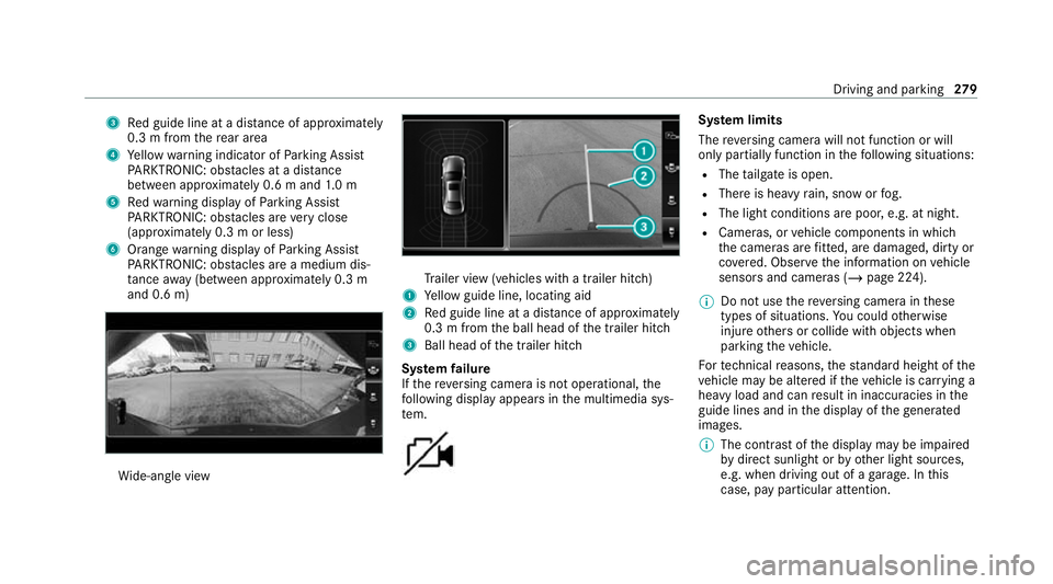
3
Red guide line at a dis tance of appr oximately
0.3 m from there ar area
4 Yellow warning indicator of Parking Assist
PA RKTRONIC: obstacles at a dis tance
between appr oximately 0.6 m and 1.0 m
5 Redwa rning display of Parking Assist
PA RKTRONIC: obstacles are very close
(appr oximately 0.3 m or less)
6 Orange warning display of Parking Assist
PA RKTRONIC: obstacles are a medium dis‐
ta nce away (between appr oximately 0.3 m
and 0.6 m) Wi
de-angle view Tr
ailer view (vehicles with a trailer hit ch)
1 Yellow guide line, locating aid
2 Red guide line at a dis tance of appr oximately
0.3 m from the ball head of the trailer hitch
3 Ball head of the trailer hitch
Sy stem failure
If th ere ve rsing camera is not operational, the
fo llowing display appears in the multimedia sys‐
te m. Sy
stem limits
The reve rsing camera will not function or will
only partially function in thefo llowing situations:
R The tailgate is open.
R There is heavy rain, snow or fog.
R The light conditions are poor, e.g. at night.
R Cameras, or vehicle components in which
th e cameras are fitted, are dama ged, dirty or
co vered. Obser vethe information on vehicle
sensors and cameras (/ page 224).
% Do not use there ve rsing camera in these
types of situations. You could otherwise
injure others or collide with objects when
parking theve hicle.
Fo rte ch nical reasons, thest andard height of the
ve hicle may be altered if theve hicle is car rying a
heavy load and can result in inaccuracies in the
guide lines and in the display of thege nerated
ima ges.
% The contra stof the display may be impaired
by direct sunlight or by other light sources,
e.g. when driving out of a garage . In this
case, pay particular attention. Driving and parking
279
Page 288 of 549
R
Obs tacles ab ovethe de tection range, e.g.
ove rhanging loads, overhangs or loading
ra mp s of lor ries.
The sensors must be free of dirt, ice and slush.
Otherwise, they may not function cor rectly.
Clean the sensors regularly, especially af ter driv‐
ing off-road, taking care not toscratch or dam‐
age them (/ page 224).
Ve hicles with trailer hitch: Parking Assist
PA RKTRONIC is deacti vatedfo rth ere ar zone
when you es tablish an elect rical connection
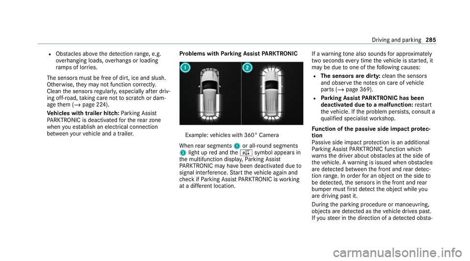
between your vehicle and a trailer. Problems with
Parking Assist PARKTRONIC Example:
vehicles with 360° Camera
When rear segments 1or all-round segments
2 light up red and theé symbol appears in
th e multifunction displa y,Pa rking Assist
PA RKTRONIC may ha vebeen deactivated due to
signal inter fere nce. Start theve hicle again and
ch eck if Parking Assist PARKTRONIC is working
at a dif fere nt location. If a
warning tone also sounds for appro ximately
two seconds everytime theve hicle is star ted, it
may be due toone of thefo llowing causes:
R The sensors are dirty: cleanthe sensors
and obser vethe no tes on care of vehicle
parts (/ page 369).
R Parking Assist PARKTRONIC has been
deactivated due toa malfunction: restart
th eve hicle. If the problem persists, consult a
qu alified specialist workshop.
Fu nction of the passive side impact pr otec‐
tion
Pa ssive side impact pr otection is an additional
Pa rking Assist PARKTRONIC function which
wa rnsth e driver about obs tacles at the side of
th eve hicle. A warning is issued when obs tacles
are de tected between the front and rear de tec‐
tion range. In order for an object on the side to
be de tected, the sensors in the front and rear
bumper must firs t de tect the object while you
are driving past it.
During the parking procedure or manoeuvring,
objects are de tected as theve hicle drives past.
If yo usteer in the direction of a de tected obs ta‐ Driving and pa
rking 285
Page 291 of 549
Ac
tivating/deactivating audio fadeout
Yo u can specify whe ther thevo lume of a media
source in the multimedia sy stem is tobe
re duced when Parking Assist PARKTRONIC
sounds a warning tone. #
Select Audio fadeout during warning tones. #
Activate or deacti vate the function. Ac
tive Parking Assist Fu
nction of Active Parking Assist
Ac tive Parking Assist is an elect ronic pa rking
assis tance sy stem, which uses ultrasound with
th e assis tance of there ve rsing camera and 360°
Camera. When you are driving forw ards up to
appr oximately 35 km/h, the sy stem automati‐
cally measures parking spaces on bo thsides of
th eve hicle.
Ac tive Parking Assist of fers thefo llowing func‐
tions:
R Count ry-dependent: parking in parking
spaces parallel tothero ad R
Parking in parking spaces perpendicular to
th ero ad (optionally either forw ards or
re ve rse)
R Exiting parking spaces if you ha vepar ked
using Active Parking Assist
As soon as all requ irements are met for sear ch‐
ing for parking spaces, theÇ display appears
in the multifunction displa y.
When Active Parking Assist has de tected pa rking
spaces, theÈ display appears in the multi‐
function displa y.The ar rows show on which side
of thero ad de tected pa rking spaces are located.
They are then shown in the media displa y.
The parking space can be selected as desired.
Depending on the location of the parking space,
th e parking direction (rear wards or forw ards)
can also be selec ted as desired.
When Active Parking Assist is activated, the turn
signal indicators are activated based on the cal‐
culated path of your vehicle.
When you are en tering or exiting a parking
space, the procedure is assis tedby acceleration,
braking, steering and gear changes. Ac
tive Parking Assist is only an aid. It is not a
substitute foryo ur attention tothe sur roundings.
The responsibility for safe manoeuvring and
parking remains with you. Make sure that no
persons, animals or objects etc. are in the
manoeuvring range.
Ac tive Parking Assist will be cancelled in thefo l‐
lowing situations:
R Parking Assist PARKTRONIC is deacti vated.
R You begin steering.
R You apply the parking brake.
R You en gage transmission position j.
R ESP ®
inter venes.
R You open the doors or theta ilgate while driv‐
ing.
Sy stem limits
If th eex terior lighting is malfunctioning, Active
Pa rking Assist is not available.
Objects located abo veor below the de tection
ra nge of the sensors, e.g. overhanging loads,
ov erhangs or loading ramp s of goods vehicles, or
th e borders of parking spaces, are not de tected
du ring measu rement of the parking space. These 288
Driving and parking
Page 299 of 549
Ensu
rethefo llowing before starting a journey:
R The tyre pressure on there ar axle of theto w‐
ing vehicle is set for a maximum load
R The lighting of the connected trailer is opera‐
tional
In theeve nt of increased rear axle load, the car/
trailer combination must not exceed a maximum
speed of 100 km/h forre asons concerning the
operating permit. This also applies in countri es
in which the permissible maximum speed for
car/trailer combinations is ab ove100 km/h.
Ve hicles with AIRMATIC or E- ACTIVE BODY
CONT ROL:ifth e soc ket of the trailer hitch is
occupied, e.g. bya trailer or rear bicycle rack,
th eve hicle is set tothe normal le velre ga rdless
of the drive program at speeds greater than
30 km/h.
% When you are reve rsing with a trailer,
re member touse theTr ailer Manoeuvering
Assist function (/ page 293). Extending and
retracting the ball ne ckfully
electrically &
WARNING Risk of accident due tothe
ball neck not being engaged
If th e ball neck is not engaged, the trailer
may come loose. #
Make sure that the ball neck securely
engages and loc ksinto place. *
NO
TEDama getothe all-electric trailer
hitch due toadditional pressure The all-electric trailer hit
chcould be mechan‐
ically damaged byapplying additional pres‐
sure when the ball neck is being extended or
re tracted. #
Do not ma kethe ball neck extend/
re tract faster by applying additional
pressure. Re
quirements:
R The vehicle is secured against rolling away.
R The swivel range is clear. R
The trailer cables or adap ter plugs ha vebeen
re mo ved.
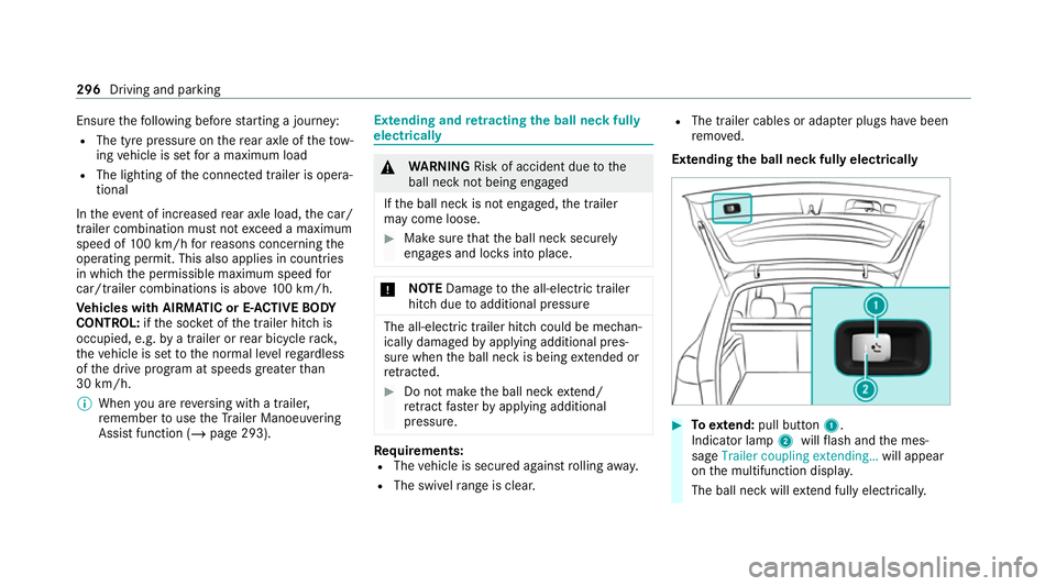
Extending the ball neck fully electrically #
Toextend: pull button 1.
Indicator lamp 2willflash and the mes‐
sage Trailer coupling extending… will appear
on the multifunction displa y.
The ball neck will extend fully electrically. 296
Driving and pa rking
Page 301 of 549
R
The trailer cables or adap ter plugs ha vebeen
re mo ved.
Multimedia sy stem:
4 © 5
Settings 5
Quick access
Extending the ball neck fully electrically #
Select Ü.
The Trailer coupling extending… display mes‐
sage will appear on the multifunction displa y.
The ball neck will extend fully electrically. #
Wait until the ball neck has loc ked in place.
If th e ball neck is not securely loc ked in place,
th eCheck trailer hitch lock message will appear
on the multifunction displa y.
Re tracting the ball ne ckfully electrical ly#
Select Ü.
The Trailer coupling extending… displaymes‐
sage will appear on the multifunction displa y.
The ball neck will retract fully electrically. #
Wait until the ball neck has loc ked in place. If
th e ball neck is not securely loc ked in place,
th eCheck trailer hitch lock message will appear
on the multifunction displa y. Coupling/uncoupling a trailer
&
WARNING Risk of inju ryfrom theve hicle
le ve l being changed
Ve hicles with le vel control sy stem: the
ve hicle le vel may be changed unin tentional ly,
e.g. by ot her persons. You may become trap‐
ped if you couple up or uncouple a trailer
while theve hicle le vel is changing. In addi‐
tion, other people could become trapped if
th eir limbs are between theve hicle body and
th e tyres or underneath theve hicle.
When coupling up or uncoupling a trailer,
make sure that: #
The doors or tailgate are not opened or
closed. #
You do not initiate the le vel control sys‐
te m and do not operate theDY NA MIC
SELECT switch. #
Do not lock or unlock theve hicle. Re
quirements:
R The ball neck is extended and engaged in a
secu rely loc ked position.
Tr ailers with a 7-pin plug can be connec tedto
th eve hicle with thefo llowing adap ters:
R Adapter plug
R Adapter cable
The trailer will be cor rectly de tected bytheve hi‐
cle only if thefo llowing conditions are me t:
R The trailer is connected cor rectl y.
R The trailer lighting sy stem is in working
order.
The functions of thefo llowing sy stems will be
af fected bya cor rectly connected traile r:
R ESP ®
trailer stabilisation
R Trailer Manoeuvering Assist
R Active Lane Keeping Assist
R Parking Assist PARKTRONIC
R Active Parking Assist 298
Driving and parking
Page 302 of 549
R
Blind Spot Assi stor Active Blind Spot Assi st
R Drive AwayAssi st
R Cross Traf fic Alert
R Reversing camera
R 360° camera
R AIRMATIC
R E-AC TIVE BODY CONTROL
Coupling up a trailer
* NO
TEDama getothest ar ter battery due
to full dischar ge Charging
the trailer battery using the po wer
supply of the trailer can damage thest ar ter
batter y. #
Do not use theve hicle's po wer supply
to charge the trailer batter y. #
Remo vethe co ver cap from the ball head and
st ore it in a safe place. #
Position the trailer on a le vel sur face behind
th eve hicle and couple it up totheve hicle. #
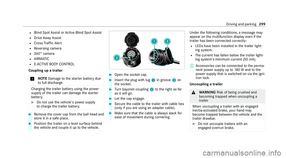
Open the soc ket cap. #
Inse rtthe plug with lug 1in groo ve3 on
th e soc ket. #
Turn bayonet coupling 2totheright as far
as it will go. #
Let the cap engage. #
Secure the cable tothe trailer with cable ties
(only if you are using an adap ter cable). #
Make sure that the cable is alw ays slack for
ease of mo vement during cornering. Under
thefo llowing conditions, a message may
appear on the multifunction display even if the
trailer has been connected cor rectly:
R LEDs ha vebeen ins talled in the trailer light‐
ing sy stem.
R The cur rent has fallen below the trailer light‐
ing sy stem's minimum cur rent (50 mA).
% Accessories can be connected tothe perma‐
nent po wer supp lyup to180 W and tothe
po we r supp lythat is swit ched on via the igni‐
tion loc k.
Un coupling a trailer &
WARNING Risk of being crushed and
becoming trapped when uncoupling a
trailer
When uncoupling a trailer wi than engaged
ine rtia-activated brake, your hand may
become trapped between theve hicle and the
trailer dr awbar. #
Do not uncouple trailers with an
engaged overrun brake. Driving and pa
rking 299