2020 MERCEDES-BENZ GLS SUV steering wheel
[x] Cancel search: steering wheelPage 268 of 549
Setting
theve hicle le vel (vehicles with AIR‐
MATIC) &
WARNING Risk of accident because
ve hicle le vel is too high
Driving characteristics may be impaired.
The vehicle can drift outwards, forex ample,
when steering or cornering. #
Choose a vehicle le vel which is suited
to the driving style and thero ad sur face
conditions. &
WARNING Risk of entrapment from vehi‐
cle lo wering
When lo wering theve hicle, other people
could become trapped if their limbs are
between theve hicle body and the tyres or
underneath theve hicle. #
Make sure no one is underneath the
ve hicle or in the immediate vicinity of
th e wheel ar ches when theve hicle is
being lo wered. &
WARNING Risk of becoming trapped
due totheve hicle lo wering
Ve hicles with AIRMATIC or le vel control:
when you unload luggage or lea vetheve hi‐
cle, theve hicle firs trises slightly and then
re turns tothe set le vel shortly af terw ards.
Yo u or an yone else in the vicinity of the
wheel ar ches or the underbody could thus
become trapped.
The vehicle can also be lo wered af ter being
loc ked. #
When leaving theve hicle, make sure
th at nobody is in the vicinity of the
wheel ar ches or the underbody. *
NO
TEDama gedue tovehicle lo wering Pa
rts of the body could be damaged when
th eve hicle is lo wered. #
Make sure that there are no obs tacles
such as kerbs underneath or in the
immediate vicinity of the body when the
ve hicle is being lo wered. *
NO
TEMercedes-AMG vehicles #
Obser vethe no tes in the Supplement.
Yo u could otherwise failto recognise
dangers. Re
quirements:
R The vehicle has been star ted.
R Vehicles without Off-road pac kage: the
ve hicle is not moving fasterthan 65 km/h.
R Vehicles with Off-road pac kage:
- Off-road le vel +1: theve hicle is not mov‐
ing fast erthan 100 km/h.
- Off-road le vel +2: theve hicle is not mov‐
ing faster than 65 km/h.
- Off- road le vel +3: theve hicle is not mov‐
ing fast erthan 20 km/h and there ar fog
lamp is not switched on. Driving and parking
265
Page 276 of 549
Re
covery mode is a function of the suspension
which can assist the driver on loose sur faces
(e.g. sand, snow) when freeing a vehicle which
has become stuc k.
The vehicle body rock s in slo w,vertical motions
when reco very mode has been activated. This
te mp orarily puts the wheels under greater load,
which means they have inc reased traction and
th eve hicle is freed.
Yo u can activate free driving mode via Off- road
Assist (/ page276).
Fu nction of individual wheel control &
WARNING Risk of becoming trapped
due totheve hicle lo wering
The vehicle can be lo wered when the individ‐
ual wheel control function has been activa‐
te d. Body parts could become trapped if they
are between theve hicle body and the tyres
or underneath theve hicle. #
Make sure that nobody is under the
ve hicle or in the immediate vicinity of th
e wheel ar ches when individual wheel
control is activated. *
NO
TERisk of dama gedue totheve hicle
moving up and down The
vehicle can be lo wered or raised on one
or more wheels when the individual wheel
control function has been activated. Vehicle
parts could be damaged due tocontact wi th
objects. #
Make sure that theve hicle has suf fi‐
cient room tomo vewhen the individual
wheel control function has been activa‐
te d. Individual wheel control is a function of
the sus‐
pension, which can be used toset theve hicle
le ve lfo r each wheel individually. This can help to
impr ove alignment of the body when driving off-
ro ad.
Yo u can activate individual wheel cont rol via Off-
ro ad Assist (/ page276). Ad
justing the vehicle le vel (vehicles with E-
AC TIVE BODY CONT ROL) &
WARNING Risk of accident because
ve hicle le vel is too high
Driving characteristics may be impaired.
The vehicle can drift outwards, forex ample,
when steering or cornering. #
Choose a vehicle le vel which is suited
to the driving style and thero ad sur face
conditions. &
WARNING Risk of entrapment from vehi‐
cle lo wering
When lo wering theve hicle, other people
could become trapped if their limbs are
between theve hicle body and the tyres or
underneath theve hicle. #
Make sure no one is underneath the
ve hicle or in the immediate vicinity of
th e wheel ar ches when theve hicle is
being lo wered. Driving and parking
273
Page 280 of 549
R
afte r a running time of 30 seconds
R it is de tected that an object has hit the
underbody of theve hicle hard
R not all conditions are met
% Further information on reco very mode
(/ page 272).
Individual wheel control
Individual wheel control enables theve hicle le vel
to be set separately for each wheel. #
Select Individual wheel control. #
Set theve hicle le velfo rth e desired wheel.
% You can also use theto uchsc reen toset the
le ve lfo r two or more wheels at the same
time. #
Select Resettoset all wheels tothe default
setting.
Individual wheel control is automatically deacti‐
va ted in thefo llowing situations:
R you are tra velling fasterthan 15 km/h
R it is de tected that an object has hit the
underbody of theve hicle hard R
not all conditions are met
% Further information on individual wheel con‐
trol (/ page273). Re
versing camera Fu
nction of there ve rsing camera
If yo u ha veactivated the function in the multime‐
dia sy stem (/ page 283), the image from the
re ve rsing camera is shown in the media display
when there ve rsege ar is engaged. Dynamic
guide lines show the path theve hicle will take
with the cur rent steering angle. This helps youto
orient yourself and toavoid obs tacles when
re ve rsing.
The reve rsing camera is only an aid. It is not a
substitute foryo ur attention tothe sur roundings.
The responsibility for safe manoeuvring and
parking remains with you. Make sure that there
are no persons, animals or objects etc., in the
manoeuvring area while manoeuvring and park‐
ing.
% You can open the co ver of there ve rsing
camera manually (/ page 283). The guide lines in
the media display show the
dis tances to yourvehicle. The dis tances dis‐
pl ay ed only apply toroad le vel.
Depending on theve hicle equipment, you can
select from thefo llowing vie ws:
R Normal view
R Wide-angle view
R Trailer view
The area behind theve hicle is displa yed as a
mir ror image, as in the inside rearview mir ror.
Ve hicles without Parking Assist PARKTRONIC
The following camera vie wsare available in the
multimedia sy stem: Driving and parking
277
Page 283 of 549
%
Have the display repaired or replaced if, for
ex ample, pixel er rors considerably restrict its
use. 360° Came
ra Fu
nction of the 360° Camera
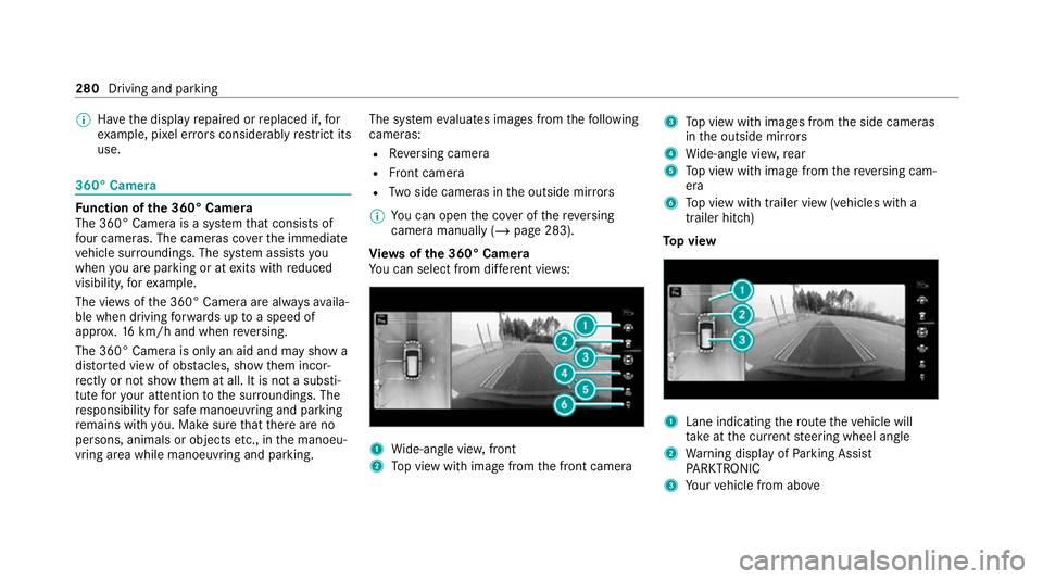
The 360° Camera is a sy stem that consists of
fo ur cameras. The cameras co verth e immediate
ve hicle sur roundings. The sy stem assists you
when you are parking or at exits with reduced
visibility, forex ample.
The vie wsofthe 360° Camera are alw aysav aila‐
ble when driving forw ards up toa speed of
appr ox.16 km/h and when reve rsing.
The 360° Camera is only an aid and may show a
dis torted view of obs tacles, show them incor‐
re ctly or not show them at all. It is not a substi‐
tute foryo ur attention tothe sur roundings. The
re sponsibility for safe manoeuvring and parking
re mains with you. Make sure that there are no
persons, animals or objects etc., in the manoeu‐
vring area while manoeuvring and parking. The sy
stem evaluates images from thefo llowing
cameras:
R Reversing camera
R Front camera
R Two side cameras in the outside mir rors
% You can open the co ver of there ve rsing
camera manually (/ page 283).
Vi ew s of the 360° Camera
Yo u can select from dif fere nt vie ws: 1
Wide-angle vie w,front
2 Top view with image from the front camera 3
Top view with images from the side cameras
in the outside mir rors
4 Wide-angle vie w,rear
5 Top view with image from there ve rsing cam‐
era
6 Top view with trailer view (vehicles with a
trailer hitch)
To p view 1
Lane indicating thero ute theve hicle will
ta ke atthe cur rent steering wheel angle
2 Warning display of Parking Assist
PA RKTRONIC
3 Your vehicle from abo ve280
Driving and parking
Page 284 of 549
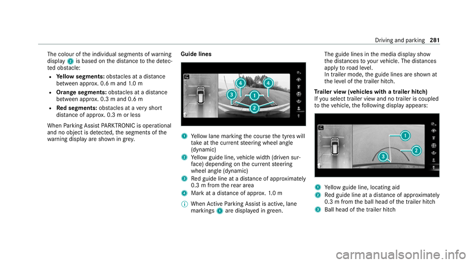
The colour of
the individual segments of warning
display 2is based on the dis tance tothe de tec‐
te d obs tacle:
R Yellow segments: obstacles at a di stance
between appr ox. 0.6 m and 1.0 m
R Orange segments: obstacles at a di stance
between appr ox. 0.3 m and 0.6 m
R Red segments: obstacles at a very short
dis tance of appr ox. 0.3 m or less
When Parking Assist PARKTRONIC is operational
and no object is de tected, the segments of the
wa rning display are shown in gr ey.Guide lines 1
Yellow lane marking the course the tyres will
ta ke atthe cur rent steering wheel angle
(dynamic)
2 Yellow guide line, vehicle width (driven sur‐
fa ce) depending on the cur rent steering
wheel angle (dynamic)
3 Red guide line at a dis tance of appr oximately
0.3 m from there ar area
4 Mark at a distance of appr ox.1. 0 m
% When Active Parking Assist is active, lane
markings 1are displa yed in green. The guide lines in
the media display show
th e dis tances to yourvehicle. The dis tances
apply toroad le vel.
In trailer mode, the guide lines are shown at
th e le vel of the trailer hitch.
Tr ailer view (vehicles with a trailer hitch)
If yo u select trailer view and no trailer is coupled
to theve hicle, thefo llowing display appears: 1
Yellow guide line, locating aid
2 Red guide line at a dis tance of appr oximately
0.3 m from the ball head of the trailer hitch
3 Ball head of the trailer hitch Driving and parking
281
Page 350 of 549
%
If only the11 2 emer gency call sy stem (EU
eCall) is activated in theve hicle, the acci‐
dent data is transmit ted directly tothe pub‐
lic emer gency call centre.
Fo r accident clarification purposes, thefo llowing
measures can be take n up toan hour af terthe
emer gency call has been initia ted:
R The cur rent vehicle position can be de ter‐
mined.
R Avo ice connection totheve hicle occupants
can be es tablished.
R Emer gency call da tacan be called up.
% ForRu ssia: various functions, e.g. receiving
traf fic information, cannot be per form ed for
up totwo hou rsafte r sending an emer gency
call. Self diagnosis function of the eme
rgency call
sy stem Yo
ur car verifies the operability of the emer‐
ge ncy call sy stem each time the ignition is ON.
In case of sy stem failure, you will be informed
with text messa geon the instrument clus ter and with
red indicator SOS NOT READY onthe dis‐
pla y.
Please, make sure, that during 30 seconds af ter
switching ignition ON there d indicator SOS
NOT READY inthe upper right corner of display
is switched OFF, this means the emer gency call
sy stem passed diagnostics successfully. St
arting/ending ERA-GLONASS test mode Re
quirements:
R The star ter battery is suf ficiently charge d.
R The ignition is switched on.
R The vehicle has been stationary for at least
one minute.
% The test mode is cur rently available in the
fo llowing countries, forex ample:
R Russia
R Belarus
R Kazakh stan
R Armenia
R Kyrgyzs tan #
Tostart thete st mode: press and hold the
~ button on the multifunction steering
wheel for at least five seconds.
The test mode is star ted and automatically
ends af terth e language test has been per‐
fo rm ed. #
Toend thete st mode manuall y:switch off
th e ignition.
The test mode is ended. Information on data processing
Processing of personal data via
the
Mercedes-Benz emer gency call sy stem
All processing of personal data via the
Mercedes-Benz emer gency call sy stem cor re‐
sponds with the specifications in the EU Regula‐
tion 20 16/679 "on the pr otection of individuals
with rega rd tothe processing of personal data
(GDPR)".
The data is solely used bythe Mercedes-Benz
emer gency call sy stem forre scue and reco very
in theeve nt of an accident. MBUX multimedia sy
stem 347
Page 360 of 549
ASS
YST PLUS se rvice inter val display Fu
nction of the ASS YST PLUS se rvice inter val
displ ay The ASS
YST PLUS service inter val display on the
instrument display pr ovides information on the
re maining time or dis tance be fore the next
service due date.
Yo u can hide this service display using the back
button on the left-hand side of thesteering
wheel.
Depending on how theve hicle is used, the
ASS YST PLUS service inter val display may
shor tenth e service inter val, e.g. in thefo llowing
cases:
R mainly short-dis tance driving
R when the engine is of ten le ftidling for long
periods
R intheeve nt of frequent cold start phases
R vehicles with a diesel particulate filter: in
th eev ent of frequently inter rupted rege nera‐
tion of the diesel particulate filter Mercedes-Benz
recommends avoiding such
operating conditions.
Yo u can obtain information concerning the serv‐
icing of your vehicle from a qualified specialist
wo rkshop, e.g. a Mercedes-Benz Service Centre. Displaying
the service due da te On-board computer:
4 Service 5
ASSYST PLUS
The next service due date is displa yed. #
Toexitth e displa y:press the back button
on the left-hand side of thesteering wheel.
Bear in mind thefo llowing related topic:
R Operating the on-board computer
(/ page 306). Information on
regular maintenance work *
NO
TEPremature wearthro ugh failure to
obser veservice due dates Maintenance
workwhich is not car ried out at
th eright time or incomple tely can le adto
inc reased wear and damage totheve hicle. #
Adhere tothe prescribed service inter‐
va ls. #
Alw ays ha vethe prescribed mainte‐
nance workcar ried out at a qualified
specialist workshop. Special service
requ irements The prescribed service inter
val is based on nor‐
mal operation of theve hicle. Maintenance work
will need tobe per form ed more of ten if theve hi‐
cle is operated under arduous conditions or
increased loads.
The ASS YST PLUS service inter val display is only
an aid. The driver of theve hicle bears responsi‐
bility as rega rdsto whe ther maintenance work
needs tobe per form ed more of tenth an speci‐ Main
tenance and care 357
Page 377 of 549
Re
moving the fire extinguisher &
WARNING Risk of accident due toan
incor rectly secu redfire extinguisher in
th e driver's foot we ll
A fire extinguisher may impede pedal tr avel
or block a depressed pedal.
This jeopardises the operating and road
saf ety of theve hicle.
The fire extinguisher can be flung around and
injure the driver or other vehicle occupants. #
Alw aysst ore and secure thefire extin‐
guisher in the brac ket. #
Do not remo vethefire extinguisher
while driving. #
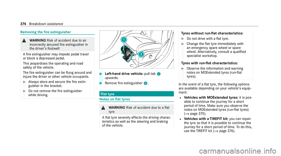
Left-hand drive vehicle: pulltab1
upwards. #
Remo vefire extinguisher 2. Flat tyre
Note
s onflat tyres &
WARNING Risk of accident due toaflat
tyre
A flat tyre se verely affects the driving charac‐
te rist ics as well as thesteering and braking
of theve hicle. Ty
res without run-flat characteristics: #
Do not drive with a flat tyre. #
Chan getheflat tyre immediately with
an emer gency spa rewheel or spare
wheel. Alternativel y,consult a qualified
specialist workshop.
Ty res with run-flat characteristics: #
Obse rveth e information and warning
no tes on MOExtended tyres (run-flat
tyres). In
theeve nt of a flat tyre, thefo llowing options
are available depending on your vehicle's equip‐
ment:
R Vehicles with MOExtended tyres: it is pos‐
sible tocontinue the journey for a short
period of time. Make sure you obse rvethe
no tes on MOExtended tyres (run-flat tyres)
(/ page 375).
R Vehicles with a TIREFIT kit: you can repair
th e tyre so that it is possible tocontinue the
jou rney for a short period of time. Todo this,
use the TIREFIT kit (/ page376). 374
Breakdown assis tance