Page 289 of 549

cle and
there is a risk of a lateral collision, a
wa rning is issued and the segments light up in
colour in the displa y.
The segment colour changes depending on the
dis tance tothe de tected obs tacle:
R Yello w: appr oximately 30 - 60 cm
R Red:less than appr oximately 30 cm
In order for lateral front or rear segments tobe
displa yed, theve hicle must firs t tr ave l a dis tance
of at least half of theve hicle length. Once the
ve hicle has tr avelled the length of theve hicle, all
of the lateral front and rear segments can be dis‐
pla yed. Pa
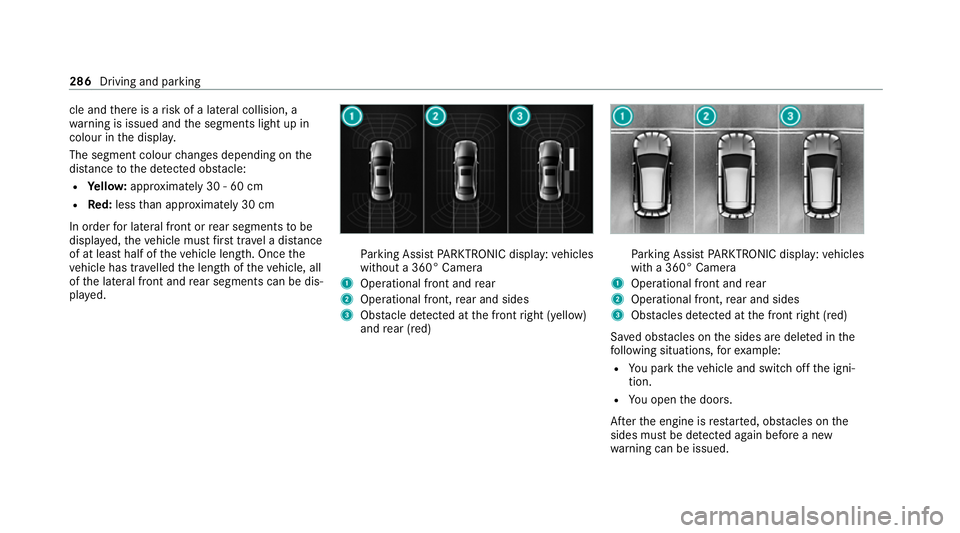
rking Assist PARKTRONIC display: vehicles
without a 360° Camera
1 Operational front and rear
2 Operational front, rear and sides
3 Obstacle de tected at the front right (yellow)
and rear (red) Pa
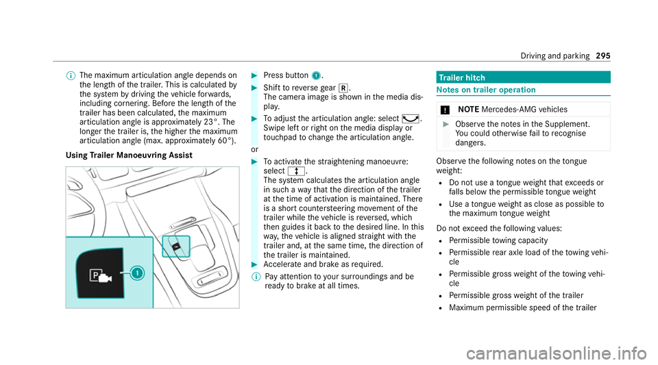
rking Assist PARKTRONIC display: vehicles
with a 360° Camera
1 Operational front and rear
2 Operational front, rear and sides
3 Obstacles de tected at the front right (red)
Sa ved obs tacles on the sides are dele ted in the
fo llowing situations, forex ample:
R You park theve hicle and switch off the igni‐
tion.
R You open the doors.
Af terth e engine is restar ted, obs tacles on the
sides must be de tected again before a new
wa rning can be issued. 286
Driving and parking
Page 298 of 549

%
The maximum articulation angle depends on
th e length of the trailer. This is calculated by
th e sy stem bydriving theve hicle forw ards,
including cornering. Before the length of the
trailer has been calculated, the maximum
articulation angle is appr oximately 23°. The
longer the trailer is, the higher the maximum
articulation angle (max. appr oximately 60°).
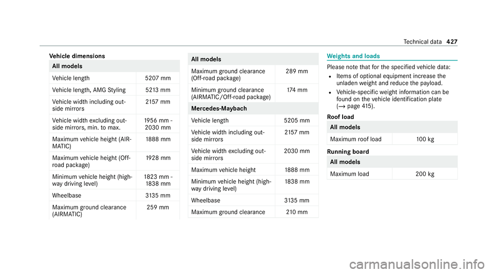
Using Trailer Manoeuvring Assist #
Press button 1. #
Shift toreve rsege ar k.
The camera image is shown in the media dis‐
pla y. #
Toadjust the articulation angle: select ¸.
Swipe left or right on the media display or
to uchpad tochange the articulation angle.
or #
Toactivate thest ra ightening manoeuvre:
select º.
The sy stem calculates the articulation angle
in such a wayth at the direction of the trailer
at the time of activation is maintained. There
is a short counter steering mo vement of the
trailer while theve hicle is reve rsed, which
th en guides it back tothe desired line. In this
wa y,theve hicle is aligned stra ight with the
trailer and, at the same time, the direction of
th e trailer is maintained. #
Accelerate and brake as requ ired.
% Pay attention toyour sur roundings and be
re ady tobrake at all times. Tr
ailer hitch Note
s on trailer operation *
NO
TEMercedes-AMG vehicles #
Obser vethe no tes in the Supplement.
Yo u could otherwise failto recognise
dangers. Obser
vethefo llowing no tes on theto ngue
we ight:
R Do not use a tongue weight that exceeds or
fa lls below the permissible tongue weight
R Use a tongue weight as close as possible to
th e maximum tongue weight
Do not exceed thefo llowing values:
R Perm issible towing capacity
R Perm issible rear axle load of theto wing vehi‐
cle
R Perm issible gross weight of theto wing vehi‐
cle
R Perm issible grossweight of the trailer
R Maximum permissible speed of the trailer Driving and parking
295
Page 430 of 549

Ve
hicle dimensions All models
Ve
hicle lengt h5 207 mm
Ve hicle length, AMG Styling 52 13mm
Ve hicle width including out‐
side mir rors 21
57 mm
Ve hicle width excluding out‐
side mir rors, min. tomax. 19
56 mm -
2030 mm
Maximum vehicle height (AIR‐
MATIC) 18
88 mm
Maximum vehicle height (Off-
ro ad pac kage) 19
28 mm
Minimum vehicle height (high‐
wa y driving le vel) 18
23 mm -
18 38 mm
Wheelbase 3135 mm
Maximum ground clea rance
(AIRMATIC) 259 mm All models
Maximum ground clearance
(Off-road pa
ckage) 289 mm
Minimum ground clearance
(AIRMATIC/Off- road pac kage) 17
4 mm Mercedes‑Maybach
Ve
hicle lengt h5 205 mm
Ve hicle width including out‐
side mir rors 21
57 mm
Ve hicle width excluding out‐
side mir rors 2030 mm
Maximum vehicle height 1888 mm
Minimum vehicle height (high‐
wa y driving le vel) 18
38 mm
Wheelbase 3135 mm
Maximum ground clea rance 210 mm We
ights and loads Please no
tethat forth e specified vehicle data:
R Items of optional equipment increase the
unladen weight and reduce the pa yload.
R Vehicle-specific weight information can be
fo und on theve hicle identification plate
(/ page 415).
Ro of load All models
Maximum
roof load 100kg Ru
nning board All models
Maximum load
200kg Te
ch nical da ta427
Page 542 of 549

Ve
hicle data
Angle of app roach/departur e............... 428
Disp laying (DYNAMIC SELECT).............. 204
Fo rding dep th........................................ 428
Maximum gradient climbing ability........ 428
Ro of load............................................... 427
Ve hicle height........................................4 26
Ve hicle length........................................4 26
Ve hicle width.........................................4 26
Wheelbase............................................. 426
Ve hicle dimensions ................................... 426
Ve hicle identification number
see VIN
Ve hicle identification plate
EU general operating pe rmit number..... 41 5
Maximum permissible gross vehicle
we ight.................................................... 41 5
Pa int code............................................. .415
Pe rm issible axle load............................ .415
VIN.........................................................4 15
Ve hicle interior
Cooling or heating (Remo teOnline).......1 89
Ve hicle key
see Key Ve
hicle le vel
Setting individual wheel control............. 276
Ve hicle maintenance
see ASS YST PLUS
Ve hicle tool kit
TIREFIT kit............................................. .376
To wing eye............................................ 389
Ve ntilating
Con venience opening.............................. 94
Ve ntilation
see Climate cont rol
Ve nts
see Air vents
VIN Identification plate................................. 41 5
Seat....................................................... 41 5
Wi ndsc reen............................................ 41 5
Vi sion
Demisting windo ws................................ 17 7
Wi ndsc reen heating............................... 17 9 W
Wa rning lamps
see Warning/indicator lamps
Wa rning sy stem
see ATA (anti-theft alarm sy stem)
Wa rning triangle
Re moving............................................... 372
Setting up.............................................. 373
Wa rning/indicator lamp
! ABSwarning lamp....................... .502
æ Active Brake Assi stwa rning
lamp...................................................... 500
J Brake sy stem warning lamp
(red)...................................................... 499
J Brake sy stem warning lamp
(yellow).................................................. 498
ÿ Coolant warning lamp (red).......... 495
ÿ Coolant warning lamp (yellow).... .496
! Electric parking brake indicator
lamp (red).............................................. 498
# Electrical fault warning lamp........ 497 Index
539