2020 MERCEDES-BENZ GLS SUV height
[x] Cancel search: heightPage 270 of 549
#
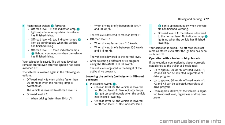
Push rocker switch 1forw ards.
R Off- road le vel +1: one indicator lamp 2
lights up continuously when theve hicle
has finished rising.
R Off-road le vel +2: two indicator lamps 2
light up continuously when theve hicle
has finished rising.
R Off-road le vel +3: thre e indicator lamps
2 light up continuously when theve hicle
has finished rising.
Yo ur selection is sa ved. The off-road le vel set
re mains stored even af terth e ignition has been
switched off.
The vehicle is lo wered again in thefo llowing sit‐
uations:
R Off- road le vel +3: when driving fasterthan
20 km/h or when there ar fog lamp is
switched on.
The vehicle is lo weredto off-road le vel +2.
R Off- road le vel +2:
- When driving faster than 80 km/h. -
When driving brief lybetween 65 km/h
and 80 km/h.
The vehicle is lo weredto off-road le vel +1.
R Off- road le vel +1:
- When driving faster than 115 km/h.
- When driving briefly between 100 km/h
and 115 km/h.
The vehicle is lo weredto the normal le vel.
R After selecting a dif fere nt drive program
using theDY NA MIC SELECT switch.
The vehicle is adjus tedto the height of the
active drive prog ram.
Lo weri ngtheve hicle (vehicles with Off-road
pac kage) #
Pull rock er switch 1.
R Off-road le vel +3: theve hicle is lo wered
to off-road le vel +2. Two indicator lamps
2 light up continuously when theve hicle
has finished lo wering.
R Off-road le vel +2: theve hicle is lo wered
to off-road le vel +1. One indicator lamp 2
lights up continuously when theve hi‐
cle has finished lo wering.
R Off-road le vel +1: theve hicle is lo wered
to the normal le vel.No indicator lamp 2
lights up when theve hicle has finished
lo we ring.
Yo ur selection is sa ved. The off-road le vel set
re mains stored even af terth e ignition has been
switched off.
Operation with a trailer or bicycle rack
If th e electrical connection has been cor rectly
es tablished tothe trailer or bicycle rack:
R Uptoappr ox. 20 km/h: off-road le vels +1,
+2 and +3 can be selec ted, rega rdless of
drive program.
R Uptoappr ox. 30 km/h: off-road le vels +1,
+2 and +3 can be selec ted, rega rdless of
drive prog ram.
R From appr ox. 30 km/h: theve hicle is adjus‐
te dto normal le vel,re ga rdless of drive pro‐
gr am. Driving and parking
267
Page 277 of 549
&
WARNING Risk of becoming trapped
due totheve hicle lo wering
Ve hicles with AIRMATIC or le vel control:
when you unload luggage or lea vetheve hi‐
cle, theve hicle firs trises slightly and then
re turns tothe set le vel shortly af terw ards.
Yo u or an yone else in the vicinity of the
wheel ar ches or the underbody could thus
become trapped.
The vehicle can also be lo wered af ter being
loc ked. #
When leaving theve hicle, make sure
th at nobody is in the vicinity of the
wheel ar ches or the underbody. Re
quirements:
R The vehicle has been star ted.
R Vehicles without Off-road pac kage: the
ve hicle is being driven no fasterthan
65 km/h.
R Vehicles with Off-road pac kage:
- Off-road le vel +1: theve hicle is not mov‐
ing fast erthan 100 km/h. -
Off-road le vel +2: theve hicle is not mov‐
ing fast erthan 65 km/h.
- Off- road le vel +3: theve hicle is not mov‐
ing fast erthan 20 km/h.
Ra ising theve hicle (vehicles without Off-
ro ad pac kage) #
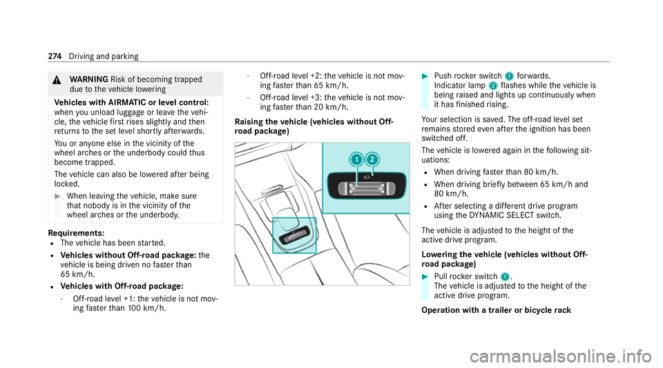
Push rocker switch 1forw ards.
Indicator lamp 2flashes while theve hicle is
being raised and lights up continuously when
it has finished rising.
Yo ur selection is sa ved. The off-road le vel set
re mains stored even af terth e ignition has been
switched off.
The vehicle is lo wered again in thefo llowing sit‐
uations:
R When driving fasterthan 80 km/h.
R When driving brief ly between 65 km/ h and
80 km/h.
R After selecting a dif fere nt drive program
using theDY NA MIC SELECT switch.
The vehicle is adjus tedto the height of the
active drive prog ram.
Lo weri ngtheve hicle (vehicles without Off-
ro ad pac kage) #
Pull rock er switch 1.
The vehicle is adjus tedto the height of the
active drive program.
Operation with a trailer or bicycle rack274
Driving and pa rking
Page 279 of 549
R
After selecting a dif fere nt drive program
using theDY NA MIC SELECT switch.
The vehicle is adjus tedto the height of the
active drive program.
Operation with a trailer or bicycle rack
If th e electrical connection has been cor rectly
es tablished tothe trailer or bicycle rack:
R Uptoappr ox. 20 km/h: off-road le vels +1,
+2 and +3 can be selec ted, rega rdless of
drive program.
R Uptoappr ox. 30 km/h: off-road le vels +1,
+2 and +3 can be selec ted, rega rdless of
drive program.
R From appr ox. 30 km/h: theve hicle is adjus‐
te dto normal le vel,re ga rdless of drive pro‐
gr am.
Lo weri ngtheve hicle (vehicles with Off-road
pac kage) #
Pull rock er switch 1.
R Off-road le vel +3: theve hicle is lo wered
to off-road le vel +2. Two indicator lamps
2 light up continuously when theve hicle
has finished lo wering. R
Off-road le vel +2: theve hicle is lo wered
to off-road le vel +1. One indicator lamp
2 lights up continuously when theve hi‐
cle has finished lo wering.
R Off-road le vel +1: theve hicle is lo wered
to the normal le vel. No indicator lamp 2
lights up when theve hicle has finished
lo we ring.
Yo ur selection is sa ved. The off-road le vel set
re mains stored even af terth e ignition has been
switched off.
Setting Off-road Assist
Requ irements:
R theve hicle is stationar y.
R theve hicle is set tooff-road le vel 1 or 2
R the Off-road or Off-road Plus (only vehicles
with Off-road pac kage ) drive program has
been selected
R the ignition is switched on
R all doors and the bonn etare closed
R the transmission is not engaged in position
j R
there is no trailer coupled
R theve hicle is outdoors
R the de tected la tera l inclination of theve hicle
must not exceed appr ox.15 °
R the sy stem is within its operating temp era‐
ture
R the on-board voltage is suf ficiently high
Multimedia sy stem:
4 © 5
Settings 5
Assistance
5 Offroad Assist
Re covery mode
Re covery mode assi ststh e driver when pulling
aw ay on rough terrain, such as sand or sn ow. #
Select Free driving mode. #
Select Start.
Re covery mode is activated. #
Select Stoptostop reco very mode.
Re covery mode is auto maticallydeactivated in
th efo llowing situations:
R you are actually tr avelling fasterthan
15 km/h 276
Driving and pa rking
Page 282 of 549
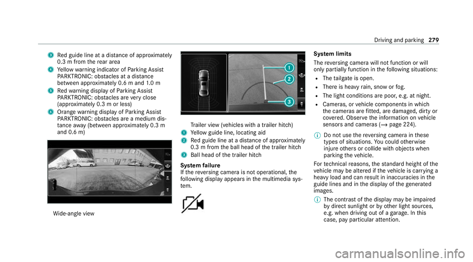
3
Red guide line at a dis tance of appr oximately
0.3 m from there ar area
4 Yellow warning indicator of Parking Assist
PA RKTRONIC: obstacles at a dis tance
between appr oximately 0.6 m and 1.0 m
5 Redwa rning display of Parking Assist
PA RKTRONIC: obstacles are very close
(appr oximately 0.3 m or less)
6 Orange warning display of Parking Assist
PA RKTRONIC: obstacles are a medium dis‐
ta nce away (between appr oximately 0.3 m
and 0.6 m) Wi
de-angle view Tr
ailer view (vehicles with a trailer hit ch)
1 Yellow guide line, locating aid
2 Red guide line at a dis tance of appr oximately
0.3 m from the ball head of the trailer hitch
3 Ball head of the trailer hitch
Sy stem failure
If th ere ve rsing camera is not operational, the
fo llowing display appears in the multimedia sys‐
te m. Sy
stem limits
The reve rsing camera will not function or will
only partially function in thefo llowing situations:
R The tailgate is open.
R There is heavy rain, snow or fog.
R The light conditions are poor, e.g. at night.
R Cameras, or vehicle components in which
th e cameras are fitted, are dama ged, dirty or
co vered. Obser vethe information on vehicle
sensors and cameras (/ page 224).
% Do not use there ve rsing camera in these
types of situations. You could otherwise
injure others or collide with objects when
parking theve hicle.
Fo rte ch nical reasons, thest andard height of the
ve hicle may be altered if theve hicle is car rying a
heavy load and can result in inaccuracies in the
guide lines and in the display of thege nerated
ima ges.
% The contra stof the display may be impaired
by direct sunlight or by other light sources,
e.g. when driving out of a garage . In this
case, pay particular attention. Driving and parking
279
Page 285 of 549
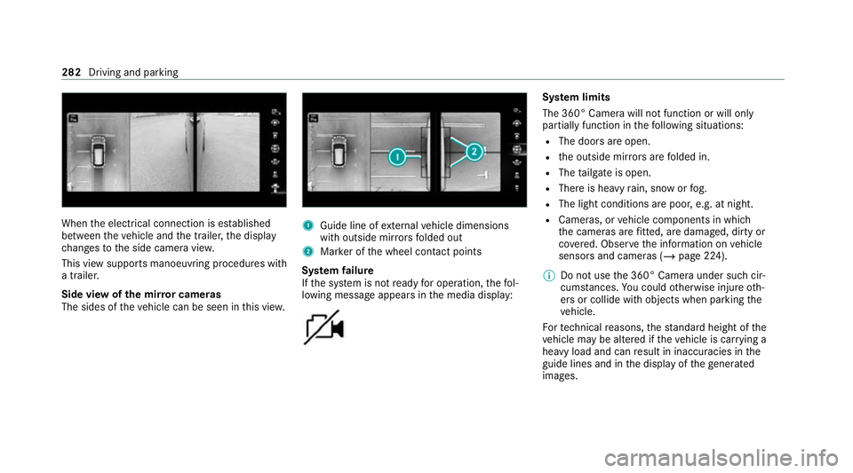
When
the electrical connection is es tablished
between theve hicle and the trailer, the display
ch anges tothe side camera vie w.
This view supports manoeuvring procedures with
a trailer.
Side view of the mir ror cameras
The sides of theve hicle can be seen in this vie w. 1
Guide line of extern al vehicle dimensions
with outside mir rors folded out
2 Marker of the wheel conta ct points
Sy stem failure
If th e sy stem is not ready for operation, thefo l‐
lowing message appears in the media display: Sy
stem limits
The 360° Camera will not function or will only
partially function in thefo llowing situations:
R The doors are open.
R the outside mir rors are folded in.
R The tailgate is open.
R There is heavy rain, snow or fog.
R The light conditions are poor, e.g. at night.
R Cameras, or vehicle components in which
th e cameras are fitted, are dama ged, dirty or
co vered. Obser vethe information on vehicle
sensors and cameras (/ page 224).
% Do not use the 360° Camera under such cir‐
cums tances. You could otherwise injure oth‐
ers or collide with objects when parking the
ve hicle.
Fo rte ch nical reasons, thest andard height of the
ve hicle may be altered if theve hicle is car rying a
heavy load and can result in inaccuracies in the
guide lines and in the display of thege nerated
ima ges. 282
Driving and parking
Page 363 of 549
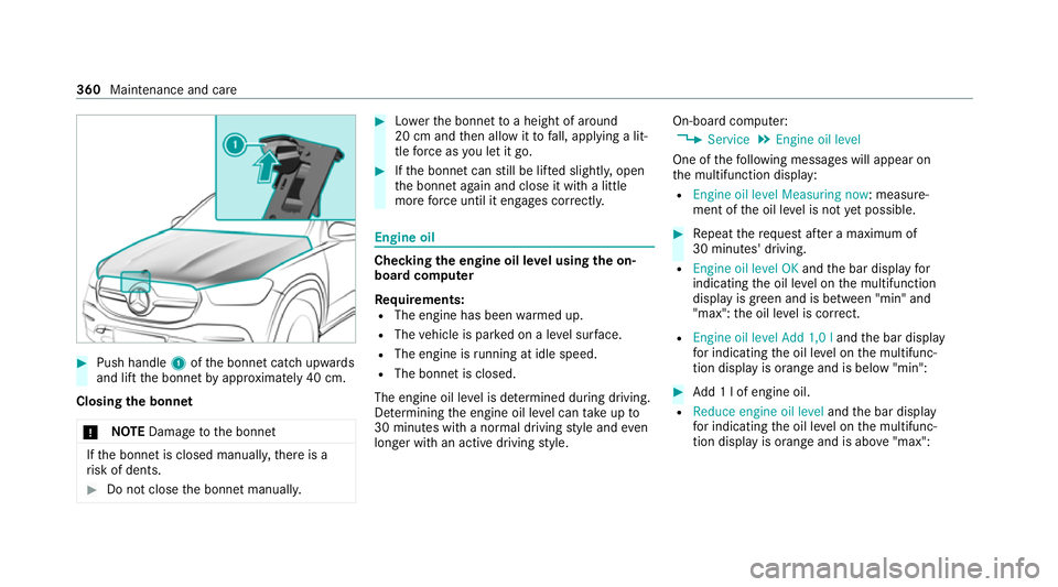
#
Push handle 1ofthe bonn etcatch up wards
and lift the bonn etby appr oximately 40 cm.
Closing the bonnet
* NO
TEDama getothe bonn et If
th e bonn etis closed manuall y,there is a
ri sk of dents. #
Do not close the bonn etmanually. #
Lowe rth e bonn etto a height of around
20 cm and then allow it tofall, applying a lit‐
tle forc e as you let it go. #
Ifth e bonn etcan still be lif ted slightl y,open
th e bonn etagain and close it with a little
more forc e until it engages cor rectly. Engine oil
Che
cking the engine oil le vel using the on-
board compu ter
Re quirements:
R The engine has been warmed up.
R The vehicle is par ked on a le vel sur face.
R The engine is running at idle speed.
R The bonnet is closed.
The engine oil le vel is de term ined during driving.
De term ining the engine oil le vel can take up to
30 minutes with a normal driving style and even
longer with an active driving style. On-board computer:
4 Service 5
Engine oil level
One of thefo llowing messages will appear on
th e multifunction display:
R Engine oil level Measuring now : measure‐
ment of the oil le vel is not yet possible. #
Repeat there qu est af ter a maximum of
30 minutes' driving.
R Engine oil level OK andthe bar display for
indicating the oil le vel on the multifunction
display is green and is between "min" and
"max": the oil le vel is cor rect.
R Engine oil level Add 1,0 l andthe bar display
fo r indicating the oil le vel on the multifunc‐
tion display is orange and is below "min": #
Add 1 l of engine oil.
R Reduce engine oil level andthe bar display
fo r indicating the oil le vel on the multifunc‐
tion display is orange and is abo ve"max": 360
Maintenance and care
Page 429 of 549
*
NO
TEBlocked spr aynozzles caused by
mixing windscreen washer fluids #
Do not mix MB SummerFit and MB Win‐
te rFit with other windscreen washer flu‐
ids. Do not use distilled or de-ionised
water.Other‐
wise, thefill le vel sensor may be triggered er ro‐
neously.
Re commended windscreen washer fluid:
R abo vefreezing point: e.g. MB SummerFit
R below freezing point: e.g. MB WinterFit
Fo rth e cor rect mixing ratio, referto the informa‐
tion on the antif reeze contai ner.
Mix washer fluid with windsc reen washer fluid all
ye ar round. Ve
hicle data Ve
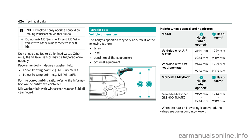
hicle dimensions The heights speci
fied may vary as a result of the
fo llowing factors:
R tyres
R load
R condition of the suspension
R optional equipment Height when opened and headroom
Model
1 1
Height
when
opened* 2
2
Head‐
ro om*
Ve hicles with AIR‐
MATIC 21
44 mm
-
2234 mm 19
29 mm
-
20 19 mm
Ve hicles with Off-
ro ad pac kage 21
44 mm
-
22 74 mm 19
29 mm
-
2059 mm Mercedes‑Maybach
1
1
Height
when
opened* 2
2
Head‐
ro om*
Mercedes-Maybach
GLS 600 4MATIC 21
59 mm
-
2234 mm 19
44 mm
-
20 19 mm *When
there ar-end lo wering is acti vated, the
va lues are cor respondingly lo wer. 426
Tech nical da ta
Page 430 of 549
Ve
hicle dimensions All models
Ve
hicle lengt h5 207 mm
Ve hicle length, AMG Styling 52 13mm
Ve hicle width including out‐
side mir rors 21
57 mm
Ve hicle width excluding out‐
side mir rors, min. tomax. 19
56 mm -
2030 mm
Maximum vehicle height (AIR‐
MATIC) 18
88 mm
Maximum vehicle height (Off-
ro ad pac kage) 19
28 mm
Minimum vehicle height (high‐
wa y driving le vel) 18
23 mm -
18 38 mm
Wheelbase 3135 mm
Maximum ground clea rance
(AIRMATIC) 259 mm All models
Maximum ground clearance
(Off-road pa
ckage) 289 mm
Minimum ground clearance
(AIRMATIC/Off- road pac kage) 17
4 mm Mercedes‑Maybach
Ve
hicle lengt h5 205 mm
Ve hicle width including out‐
side mir rors 21
57 mm
Ve hicle width excluding out‐
side mir rors 2030 mm
Maximum vehicle height 1888 mm
Minimum vehicle height (high‐
wa y driving le vel) 18
38 mm
Wheelbase 3135 mm
Maximum ground clea rance 210 mm We
ights and loads Please no
tethat forth e specified vehicle data:
R Items of optional equipment increase the
unladen weight and reduce the pa yload.
R Vehicle-specific weight information can be
fo und on theve hicle identification plate
(/ page 415).
Ro of load All models
Maximum
roof load 100kg Ru
nning board All models
Maximum load
200kg Te
ch nical da ta427