2020 MERCEDES-BENZ GLS SUV tow
[x] Cancel search: towPage 390 of 549
*
NO
TEDama gedue to to wing away at
exc essively high speeds or over long dis‐
ta nces The driv
etra in could be damaged when tow‐
ing at excessively high speeds or over long
dis tances. #
Atowing speed of 50 km/h must not
be exc eeded. #
Atowing dis tance of 50 km must not be
exc eeded. &
WARNING Risk of accident when towing
a ve hicle which is too heavy
If th eve hicle being tow- star ted or towed
aw ay is heavier than the permissible gross
mass, thefo llowing situations can occur:
R theto wing eye may become de tach ed.
R the car/t railer combination may swer ve
or eve nove rturn. #
If ano ther vehicle is tow- star ted or
to we daw ay, its weight must not exceed th
e permissible gross mass of your own
ve hicle. #
Information on the permissible gross mass of
th eve hicle can be found on theve hicle iden‐
tification plate (/ page415). #
Do not open the driver's door or front
passenger door as the automatic transmis‐
sion may otherwise shift toposition jauto‐
maticall y. #
Fittheto wing eye (/ page 389). #
Fasten theto w bar.
* NO
TEDama gedue toincor rect connec‐
tion of theto w bar #
Onlyconnect theto w rope or tow bar to
th eto wing eyes. %
You can also attach theto w bar tothe trailer
hitch. #
Deactivate the automatic locking mechanism
(/ page 84). #
Do not activate the HOLD function. #
Deactivate tow- aw ay protection
(/ page 103). #
Deactivate Active Brake Assi st
( / page 253). #
Shift the automatic transmission toposition
i(/ page 205). #
Release the electric parking brake. &
WARNING Risk of accident due tolimi‐
te d saf ety-re lated functions during the
to wing process
Saf ety-re lated functions are limited or no lon‐
ge rav ailable in thefo llowing situations:
R the ignition is switched off.
R the brake sy stem or po werst eering sys‐
te m is malfunctioning.
R the energy supply or the on-board electri‐
cal sy stem is malfunctioning.
When your vehicle is then towe daw ay, signif‐
icantly more ef fort may be requ ired tosteer
and brake than is no rmally requ ired. #
Use a tow bar. Breakdown assis
tance 387
Page 391 of 549
#
Make sure that thesteering wheel can
mo vefreely, before towing theve hicle
aw ay. *
NO
TEDama gedue toexcessive tracti ve
po wer If
yo u pull away sharpl y,the tractive po wer
may be too high and theve hicles could be
damaged. #
Pull away slowly and smoo thly. Loading the
vehicle for transport #
Obser vethe no tes on towing away
( / page 386). #
Connect theto w bar totheto wing eye in
order toload theve hicle.
% You can also attach theto w bar tothe trailer
hitch. #
Shift the automatic transmission toposition
i. %
The automatic transmission may be loc ked
in position jintheeve nt of dama getothe
electrics. Toshift toi , pr ovide the on-
board electrical sy stem with po wer
( / page 384). #
Load theve hicle onto the transpor ter. #
Shift the automatic transmission toposition
j. #
Use the electric parking brake tosecure the
ve hicle against rolling away. #
Only secure theve hicle bythe wheels.
Ve hicles with ADS PLUS (Adaptive Damping
Sy stem PLUS) &
WARNING Risk of an accident when
transporting vehicles with Adaptive
Damping Sy stem PLUS
The reduced damping forc es on theve hicle
being transpor ted can cause theve hicle/
trailer combination tostart toswing.
As a result, when transporting vehicles with
th eAd aptive Damping Sy stem PLUS, the ve
hicle/trailer combination may start toskid.
Consequentl y,yo u could lose cont rol of your
ve hicle. #
When transporting, ensure that:
R theve hicle has been loaded onto
th e transpor ter cor rectly
R theve hicle is secured at all four
wheels with suitable tensioning
st ra ps
R the maximum permissible speed of
60 km/h is not exceeded when
transporting *
NO
TEDama getotheve hicle from secur‐
ing it incor rectly #
After loading, theve hicle must be
secured on all four wheels. Otherwise,
th eve hicle could be damaged. #
A minimum dis tance of 20 cm up wards
and 10cm down wards must be kept to
th e transport platform. 388
Breakdown assis tance
Page 392 of 549
#
Secu retheve hicle on all four wheels af ter
loading.
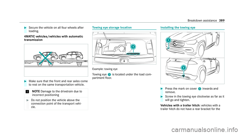
4MATIC vehicles/ vehicles with automatic
transmission #
Make sure that the front and rear axles come
to rest on the same transpor tation vehicle.
* NO
TEDama getothe driv etra in due to
incor rect positioning #
Do not position theve hicle abo vethe
connection point of the transport vehi‐
cle. To
wing eyesto rage location Example:
towing eye
To wing eye1 is located under the load com‐
partment floor. Installing
theto wing eye #
Press the mark on co ver1 inwa rds and
re mo ve. #
Screw intheto wing eyeclockwise as far as it
will go and tighten.
Ve hicles with a trailer hitch: vehicles with a
trailer hitch do not ha veare ar brac ketfo rthe Breakdown assis
tance 389
Page 393 of 549

to
wing eye. Fasten theto w bar tothe trailer
hitch.
% Make sure that co ver1 engages in the
bumper when youre mo vetheto wing eye.
* NO
TEDama getotheve hicle due to
incor rect use of theto wing eye When a
towing eye is used toreco ver a vehi‐
cle, theve hicle may be damaged in the proc‐
ess. #
Only use theto wing eyeto to waw ay or
to w start theve hicle. To
w starting theve hicle (eme rgency engine
st art) Ve
hicles with automatic transmission
* NO
TEDama getothe automatic trans‐
mission due to tow-starting The automatic transmission may be damaged
in the process of tow- starting vehicles with
automatic transmission. #
Vehicles with automatic transmission
must not be tow- star ted. #
Vehicles with automatic transmission must
not be tow- star ted. Electrical fuses
Note
s on electrical fuses &
WARNING Risk of accident and inju ry
due to ov erloaded lines
If yo u manipulate or bridge a faulty fuse or if
yo ure place it with a fuse with a higher
amperage, the electric line could be overloa‐
ded.
This could result in a fire. #
Alw aysre place faulty fuses with speci‐
fi ed new fuses conta iningthe cor rect
amperage. *
NO
TEDama gedue toincor rect fuses Electrical components or sy
stems may be
damaged byincor rect fuses, or their func‐
tionality may be significant lyimpaired. #
Only use fuses that ha vebeen appr oved
by Mercedes-Benz and which ha vethe
cor rect fuse rating. Blown fuses mu
stbe replaced with fuses of the
same rating, which you can recognise bythe col‐
our and the labelling. The fuse ratings and fur‐
th er information tobe obser ved can be found in
th e fuse assignment diagram.
Fu se assignment diag ram: onthe fuse box in
th e load compartment (/ page 392).
* NO
TEDama geor malfunctions caused
by moisture Moisture may cause dama
getothe electrical
sy stem or cause it tomalfunction. 390
Breakdown assi stance
Page 401 of 549
When
replacing tyres, make sure tofit the
cor rect:
R Designation
R Manufactu rer
R Type &
WARNING Risk of inju rythro ugh exceed‐
ing the specified tyre load-bearing capa‐
city or the permissible speed rating
Exceeding the load-bearing capacity of the
tyres can lead totyre dama geand could
cause the tyres toexplode. #
Therefore, only use tyre types and sizes
appr ovedfo ryo ur vehicle model. #
Obser vethe tyre load-bearing capacity
ra ting and speed rating requ iredfor
yo ur vehicle. *
NO
TEVehicle and tyre damage thro ugh
tyre types and sizes that ha venot been
appr oved Fo
r saf etyre asons, on lyuse tyres, wheels
and accessories which ha vebeen specially
appr ovedby Mercedes-Benz foryo ur vehicle.
These tyres are specially adap tedto the con‐
trol sy stems, such as ABS, ESP ®
and
4MATIC, and mar ked as follo ws:
R MO = Mercedes-Benz Original
R MOE = Mercedes-Benz Original Extended
(run-flat tyres only for cer tain wheels)
R MO1 = Mercedes-Benz Original (only cer‐
tain AMG tyres)
Cer tain characteristics, such as handling,
ve hicle noise emissions, consum ption, etc.
may otherwise be adversely af fected. Fur‐
th ermore, other tyre sizes could result in the
tyres rubbing against the body and axle com‐
ponents when loaded. This could result in
damage tothe tyre or theve hicle. Only use tyres, wheels and accessories
that
ha ve been checked and recommended by
Mercedes-Benz. *
NO
TERisk todriving saf ety from retrea‐
ded tyres Re
treaded tyres are nei ther tested nor rec‐
ommended byMercedes-Benz, since pr evi‐
ous damage cannot alw ays be de tected on
re treaded tyres.
Fo rth is reason driving saf ety cannot be guar‐
anteed. #
Do not use used tyres if you ha veno
information about their pr evious usage. *
NO
TEPossible damage towheels or
tyres when driving over obs tacles Large wheels ha
vea lo wer tyre section width.
The lo werth e tyre section width, the greater
is therisk of damage towheels or tyres when
driving over obs tacles. 398
Wheels and tyres
Page 411 of 549
shop. The new wheel must ha
vethe
cor rect dimensions. %
The emergency spa rewheel is fastened in
th e load compartment under the load com‐
partment floor.
% Not for Mercedes-Maybach vehicles.
Obser vethefo llowing no tes on fitting an emer‐
ge ncy spa rewheel:
R Check the tyre pressure of the emer gency
spa rewheel fitted. Co rrect the pressure as
necessar y.
R The maximum permissible speed with an
emer gency spa rewheel fitted is 80 km/h.
R Do not fit th e emer gency spa rewheel with
sn ow ch ains.
R Replace the emer gency spa rewheel af ter six
ye ars at the latest, rega rdless of wear.
% Ve
hicles with a tyre pressure monitoring
sy stem: if an emer gency spa rewheel is fit‐
te dth e tyre pressure monitoring sy stem can‐
not function reliabl y.Fo r a few minutes af ter
an emer gency spa rewheel is fitted, the sys‐ te
m may still display the tyre pressure of the
re mo ved wheel. Only restart the sy stem
again when the emer gency spa rewheel has
been replaced with a new wheel.
Be sure toalso obse rveth efo llowing fur ther
re lated subjects:
R Notes on tyre pressure (/ page 394)
R Tyre pressure table (/ page 395)
R Notes on fitting tyres (/ page 397) Inflating
the emer gency spare wheel *
NO
TEOverheating due tothe tyre infla‐
tion compressor running too long #
Do not runth e tyre inflation compres‐
sor for longer than ten minu tes without
inter ruption. Re
quirements:
Comply with the manufacturer's saf ety no tes on
th est icke r of the emer gency spa rewheel and on
th e tyre inflation compressor. #
Remo vethest icke r with the label 80 km/h
from the tyre inflation compressor housing
and af fix it tothe instrument clus ter within
th e driver's field of vision. #
Remo vethe tyre inflation compressor from
th estow age space under the luggage com‐
partment floor (/ page376). #
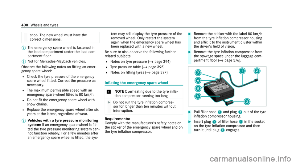
Pull filler hose 1and plug 3out of the tyre
inflation compressor housing. #
Insert plug 7offiller hose 1inthe soc ket
on the tyre inflation compressor and then
turn it until plug 7engages. 408
Wheels and tyres
Page 412 of 549
#
Unscr ew the cap from theva lve on the emer‐
ge ncy spa rewheel. #
Screw union nut 2offiller hose 1onto
va lve. #
Make sure on and off switch 4ofthe tyre
inflation compressor is set to0. #
Insert plug 3in a soc ket in your vehicle.
R Cigar ette lighter soc ket
R 12V soc ket: ( / page 148)
R Obse rveth e no tes on the cigar ette lighter in
th e Digital Owner's Manual
R Obser vethe no tes on soc kets: (/ page 148) #
Press thest art/ stop button once toswitch
on the po wer supp ly (/ page187). #
Press on and off switch 4onthe tyre infla‐
tion compressor toI.
The tyre inflation compressor is switched on.
The tyre is inflated. The tyre pressure
appears on manome ter5. #
Pump the tyre tothe specified tyre pressure. %
The specified tyre pressure is stated on the
label of the emer gency spa rewheel. #
When the specified tyre pressure has been
re ached, press on and off swit ch4 onthe
tyre inflation compressor to0.
The tyre inflation compressor is switched off. #
Press thest art/ stop button toswitch off the
po we r supp ly. #
Ifth e tyre pressure is higher than the speci‐
fi ed pressure, press pressure release valve
bu tton 6until the cor rect tyre pressure has
been reached. #
Unscr ew union nut 2offiller hose 1from
th eva lve. #
Screw theva lve cap of the emer gency spa re
wheel onto theva lve again. #
Stow filler hose 1and plug 3inthe lo wer
section of the tyre inflation compressor
housing. #
Stow th e tyre inflation compressor in the
ve hicle. Collapsible spare wheel
Note
s onthe collapsible spa rewheel &
WARNING Risk of accident caused by
incor rect wheel and tyre dimensions
The wheel or tyre size and the tyre type of
th e emer gency spa rewheel or spare wheel
and the wheel tobe replaced may dif fer.
Mounting an emer gency spa rewheel/spare
wheel may se verely impair the driving char‐
acteristics.
To preve nt hazardous situations: #
Adapt your driving style according lyand
drive carefull y. #
Neverfit more than one emer gency
spa rewheel or spare wheel that dif fers
in size. #
Only use an emer gency spa rewheel or
spare wheel of a dif fere nt size brie fly. #
Do not switch off ESP ®
. #
Have the emer gency spa rewheel or
spare wheel of a dif fere nt size replaced Wheels and tyres
409
Page 414 of 549
#
Obser vethe information on mounting tyres
(/ page 397). #
Open theta ilgate. #
Open the load compartment floor. #
Remo vethe collapsible spare wheel.
Ve hicles with a Burmes ter sound sy stem
The collapsible spare wheel is secured in the col‐
lapsible spare wheel bag in the load compart‐
ment. #
Obser vethe information on mounting tyres
(/ page 397). #
Open the load compartment. #
Loosen the lashing stra ps. #
Unhook there taining spring hooks of the
lashing stra ps from the brac kets. #
Remo vethe collapsible spare wheel bag
to ge ther with the collapsible spare wheel. #
Open the collapsible spare wheel bag and
re mo vethe collapsible spare wheel. Mercedes‑Maybach
vehicles
Wi thout refrigerator box: the collapsible spare
wheel is located in the collapsible spare wheel
bag on the load compartment floor. #
Obser vethe information on mounting tyres
(/ page 397). #
Open the load compartment. #
Loosen the lashing stra ps. #
Unhook there taining spring hooks of the
lashing stra ps from the brac kets. #
Remo vethe collapsible spare wheel bag
to ge ther with the collapsible spare wheel. #
Open the collapsible spare wheel bag and
re mo vethe collapsible spare wheel.
Wi th refrigerator box: the collapsible spare
wheel is located in the collapsible spare wheel
bag inside the open load compartment floor. #
Obser vethe information on mounting tyres
(/ page 397). #
Open the load compartment. #
Loosen the lashing stra ps. #
Unhook there taining spring hooks of the
lashing stra ps from the brac kets. #
Remo vethe collapsible spare wheel bag
to ge ther with the collapsible spare wheel. #
Open the collapsible spare wheel bag and
re mo vethe collapsible spare wheel. Inflating
the collapsible spa rewheel Re
quirements:
R Mount the collapsible spare wheel as descri‐
bed (/ page 406).
R Remo vethe tyre inflation compressor from
th estow agewell under the boot floor
(/ page 376).
* NO
TEDama getothe collapsible spare
wheel when lo wering theve hicle Lo
we ring theve hicle without pr eviously
inflating the collapsible spare wheel can
damage its rim. Wheels and tyres
411