2020 MERCEDES-BENZ GLE COUPE inflation pressure
[x] Cancel search: inflation pressurePage 542 of 757
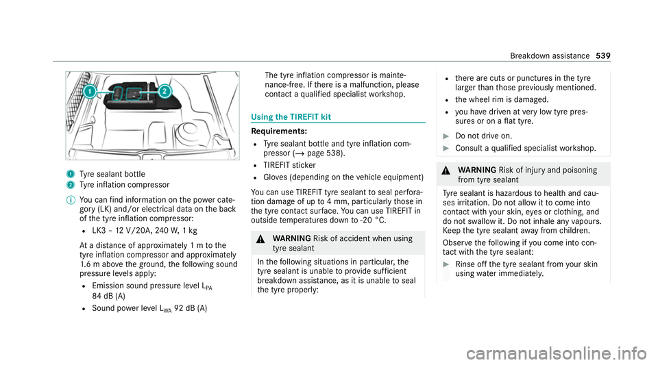
1
Tyre sealant bottle
2 Tyre inflation compressor
% You can find information on the po wer cate‐
gory (LK) and/or electrical data on the back
of the tyre inflation compressor:
R LK3 – 12V/20A, 240W, 1kg
At a dis tance of appr oximately 1 m tothe
tyre inflation compressor and appr oximately
1. 6 m abo vethe ground, thefo llowing sound
pressure le vels apply:
R Emission sound pressure le vel L
PA
84 dB (A)
R Sound po wer le vel L
WA 92 dB (A) The tyre inflation compressor is mainte‐
nance-free. If
there is a malfunction, please
conta ct aqualified specialist workshop. Using
the TIREFIT kit Re
quirements:
R Tyre sealant bottle and tyre inflation com‐
pressor (/ page 538).
R TIREFIT sticker
R Gloves (depending on theve hicle equipment)
Yo u can use TIREFIT tyre sealant toseal per fora‐
tion dama geof up to4 mm, particularly those in
th e tyre conta ct surface. You can use TIREFIT in
outside temp eratures down to-20 °C. &
WARNING Risk of accident when using
tyre sealant
In thefo llowing situations in particular, the
tyre sealant is unable toprov ide suf ficient
breakdown assis tance, as it is unable toseal
th e tyre proper ly: R
there are cuts or punctures in the tyre
larger than those pr eviously mentioned.
R the wheel rim is dama ged.
R you ha vedriven at very low tyre pres‐
sures or on a flat tyre. #
Do not drive on. #
Consult a qualified specialist workshop. &
WARNING Risk of inju ryand poisoning
from tyre sealant
Ty re sealant is hazardous tohealth and cau‐
ses ir rita tion. Do not allow it tocome into
contact wi thyour skin, eyes or clo thing, and
do not swallow it. Do not inhale any vapours.
Ke ep the tyre sealant away from children.
Obser vethefo llowing if you come into con‐
ta ct wi th the tyre sealant: #
Rinse off the tyre sealant from your skin
using water immediatel y. Breakdown assis
tance 539
Page 544 of 757
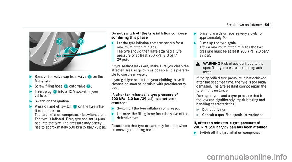
#
Remo vetheva lve cap from valve 7 onthe
fa ulty tyre. #
Screw filling hose 8onto valve 7. #
Insert plug 4into a 12V soc ket in your
ve hicle. #
Switch on the ignition. #
Press on and off switch 3onthe tyre infla‐
tion compressor.
The tyre inflation compressor is switched on.
The tyre is inflated. Fir st, tyre sealant is pum‐
ped into the tyre. The pressure may brief ly
ri se toappr oximately 500 kPa (5 bar/73 psi). Do not switch off
the ty reinflation compres‐
sor during this phase! #
Let the tyre inflation compressor runfo r a
maximum of ten minu tes.
The tyre should then ha veattained a tyre
pressure of at least 200 kPa (2.0 bar/
29 psi).
If tyre sealant leaks out, make sure you clean the
af fected area as quickly as possible. It is prefera‐
ble touse clean water.
If yo uge t tyre sealant on your clo thing, ha veit
cleaned as soon as possible with per chloroe thy‐
lene.
If, af terte n minutes, a tyre pressure of
200 kPa (2.0 bar/29 psi) has not been
attained: #
Switch off the tyre inflation compressor. #
Unscr ew thefilling hose from theva lve of the
defective tyre.
Please no tethat tyre sealant may leak out when
unscr ewing thefilling hose. #
Drive forw ards or reve rseve ry slowly for
appr oximately 10m. #
Pump up the tyre again.
Af ter a maximum of ten minu testh e tyre
pressure must be at least 200 kPa (2.0 bar/
29 psi). &
WARNING Risk of accident due tothe
specified tyre pressure not being ach‐
ie ved
If th e specified tyre pressure is not achie ved
af te rth e specified time, the tyre is too badly
damaged. The tyre sealant cannot repair the
tyre in this ins tance.
Dama ged tyres and a tyre pressure that is
to o low can significantly impair braking and
handling characteristics. #
Do not drive on. #
Consult a qualified specialist workshop. If, af
terte n minutes, a tyre pressure of
200 kPa (2.0 bar/29 psi) has been attained: #
Switch off the tyre inflation compressor. Breakdown assis
tance 541
Page 545 of 757
#
Unscr ew thefilling hose from theva lve of the
defective tyre. &
WARNING Risk of accident from driving
wi th sealed tyres
A tyre temp orarily sealed with tyre sealant
impairs driving characteristics and is not
suitable for higher speeds. #
Adapt your driving style according lyand
drive carefull y. #
Do not exceed the maximum speed
limit with a tyre that has been repaired
using tyre sealant. #
Obser vethe maximum permissible speed for
a tyre sealed with tyre sealant 80 km/h. #
Affix th e upper section of the TIREFIT sticker
to the instrument clus ter in a location where
it will be easi lyseen bythe driver.
* NO
TEStaining from leaking tyre sealant Af
ter use, excess tyre sealant may leak out
from thefilling hose. #
Therefore, place thefilling hose in the
plastic bag that con tained the TIREFIT
kit. +
ENVIRONMEN
TALNO TEEnvironmental
pollution caused byenvironmen tally ir re‐
sponsible disposal Ty
re sealant contains polluta nts. #
Have the tyre sealant bottle disposed of
professionall y,e.g. at a Mercedes-Benz
Service Centre. #
Stow th e tyre sealant bottle, the tyre inflation
compressor and thewa rning triangle. #
Pull away immediatel y. #
Stop driving af ter appro ximately ten minu tes
and check the tyre pressure using the tyre
inflation compressor.
The tyre pressure must now be at least
13 0 kPa (1.3 bar/19 psi). &
WARNING Risk of accident due tothe
specified tyre pressure not being ach‐
ie ved
If th e specified tyre pressure is not achie ved
af te r a brief drive, the tyre is too badly dam‐
aged. The tyre sealant cannot repair the tyre
in this ins tance.
Dama ged tyres and a tyre pressure that is
to o low can significantly impair braking and
handling characteristics. #
Do not drive on. #
Consult a qualified specialist workshop. Countries
that ha veMercedes-Benz
Service24h: you will find a sticke r with thete le‐
phone number, e.g. on the B‑pillar on the driver's
side. #
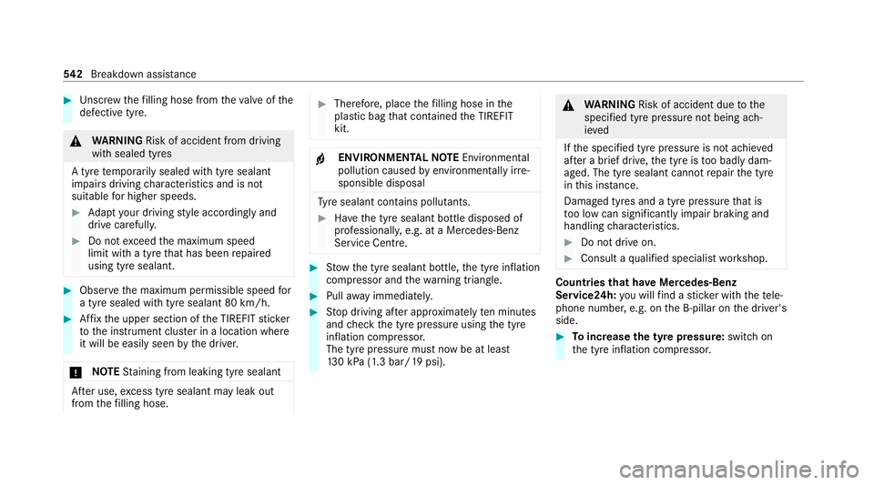
Toincrease the ty repressure: switch on
th e tyre inflation compressor. 542
Breakdown assis tance
Page 546 of 757
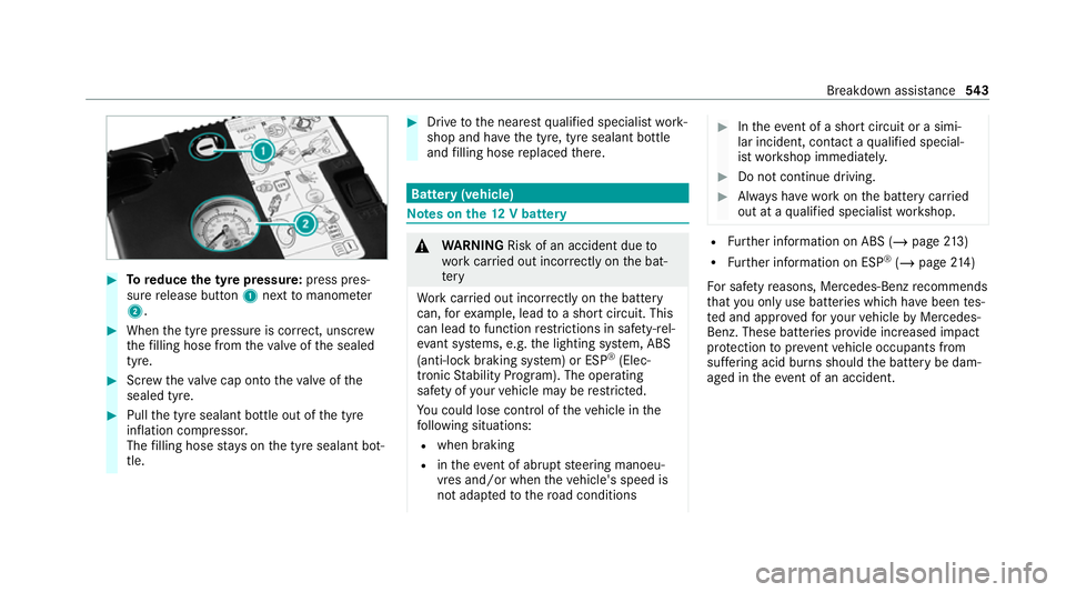
#
Toreduce the tyre pressure: press pres‐
su re re lease button 1next tomanome ter
2 . #
When the tyre pressure is cor rect, unscr ew
th efilling hose from theva lve of the sealed
tyre. #
Screw theva lve cap onto theva lve of the
sealed tyre. #
Pull the tyre sealant bottle out of the tyre
inflation compressor.
The filling hose stay s on the tyre sealant bot‐
tle. #
Drive tothe nearest qualified specialist work‐
shop and ha vethe tyre, tyre sealant bottle
and filling hose replaced there. Batte
ry(vehicle) Note
s onthe12 V battery &
WARNING Risk of an accident due to
wo rkcar ried out incor rectly on the bat‐
te ry
Wo rkcar ried out incor rectly on the battery
can, forex ample, lead toa short circuit. This
can lead tofunction restrictions in saf ety-re l‐
eva nt sy stems, e.g. the lighting sy stem, ABS
(anti-lock braking sy stem) or ESP ®
(Elec‐
tronic Stability Prog ram). The operating
saf ety of your vehicle may be restricted.
Yo u could lose cont rol of theve hicle in the
fo llowing situations:
R when braking
R intheeve nt of ab rupt steering manoeu‐
vres and/or when theve hicle's speed is
not adap tedto thero ad conditions #
Intheeve nt of a sho rtcircuit or a simi‐
lar incident, contact a qualified special‐
ist workshop immediately. #
Do not continue driving. #
Alw ays ha vewo rkon the battery car ried
out at a qualified specialist workshop. R
Further information on ABS (/ page213)
R Further information on ESP ®
(/ page 214)
Fo r saf etyre asons, Mercedes-Benz recommends
th at you on lyuse bat teries which ha vebeen tes‐
te d and appr ovedfo ryo ur vehicle byMercedes-
Benz. These batteries pr ovide inc reased impact
pr otection topreve ntvehicle occupants from
suf fering acid bu rns should the battery be dam‐
aged in theeve nt of an accident. Breakdown assi
stance 543
Page 578 of 757
shop. The new wheel must ha
vethe
cor rect dimensions. Check
the tyre pressure of the emer gency spa re
wheel fitted. Co rrect the pressure as necessar y.
The maximum permissible speed with an emer‐
ge ncy spa rewheel fitted is 80 km/h.
Do not fit th e emer gency spa rewheel with sn ow
ch ains.
Re place the emer gency spa rewheel af ter six
ye ars at the latest, rega rdless of wear.
% Ve
hicles with a tyre pressure monitoring
sy stem: if an emer gency spa rewheel is fit‐
te dth e tyre pressure monitoring sy stem can‐
not function reliabl y.Fo r a few minutes af ter
an emer gency spa rewheel is fitted, the sys‐
te m may still display the tyre pressure of the
re mo ved wheel. Only restart the sy stem
again when the emer gency spa rewheel has
been replaced with a new wheel.
Be sure toalso obse rveth efo llowing fur ther
re lated subjects:
R Notes on tyre pressure (/ page 557)R
Tyre pressure table (/ page 558) Re
moving the eme rgency spa rewheel The eme
rgency spare wheel is located under the
load compartment floor.
% Not for Mercedes-Maybach vehicles. #
Obser vethe information on mounting tyres
(/ page 564). #
Open theta ilgate. #
Open the load compartment floor
(/ page 128). #
Remo vethe emer gency spa rewheel bag with
th e emer gency spa rewheel. #
Open the emer gency spa rewheel bag and
re mo vethe emer gency spa rewheel. Inflating
the emer gency spare wheel *
NO
TEOverheating due tothe tyre infla‐
tion compressor running too long #
Do not runth e tyre inflation compres‐
sor for longer than ten minu tes without
inter ruption. %
Comply with the manufacturer's saf ety no tes
on thest icke r of the emer gency spa rewheel
and on the tyre inflation compressor. #
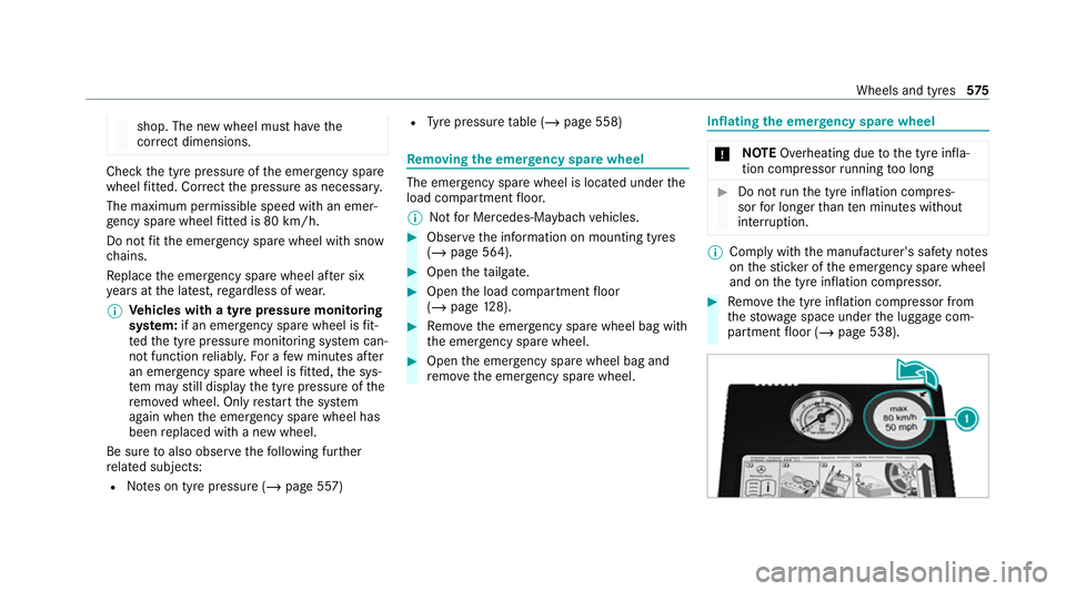
Remo vethe tyre inflation compressor from
th estow age space under the luggage com‐
partment floor (/ page 538). Wheels and tyres
575
Page 579 of 757
#
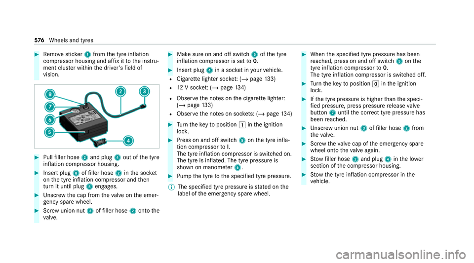
Remo vesticke r1 from the tyre inflation
compressor housing and af fix it tothe instru‐
ment clus ter within the driver's field of
vision. #
Pull filler hose 2and plug 4out of the tyre
inflation compressor housing. #
Insert plug 8offiller hose 2inthe soc ket
on the tyre inflation compressor and then
turn it until plug 8engages. #
Unscr ew the cap from theva lve on the emer‐
ge ncy spa rewheel. #
Screw union nut 3offiller hose 2onto the
va lve. #
Make sure on and off switch 5ofthe tyre
inflation compressor is set to0. #
Insert plug 4in a soc ket in your vehicle.
R Cigar ette lighter soc ket: ( / page 133)
R 12V soc ket: ( / page 134)
R Obse rveth e no tes on the cigar ette lighter:
(/ page 133)
R Obse rveth e no tes on soc kets: (/ page 134) #
Turn theke yto position 0047inthe ignition
loc k. #
Press on and off switch 5onthe tyre infla‐
tion compressor toI.
The tyre inflation compressor is switched on.
The tyre is inflated. The tyre pressure is
shown on manome ter6. #
Pump the tyre tothe specified tyre pressure.
% The specified tyre pressure is stated on the
label of the emer gency spa rewheel. #
When the specified tyre pressure has been
re ached, press on and off swit ch5 onthe
tyre inflation compressor to0.
The tyre inflation compressor is switched off. #
Turn theke yto position 005Ainthe ignition
loc k. #
Ifth e tyre pressure is higher than the speci‐
fi ed pressure, press pressure release valve
bu tton 7until the cor rect tyre pressure has
been reached. #
Unscr ew union nut 3offiller hose 2from
th eva lve. #
Screw theva lve cap of the emer gency spa re
wheel onto theva lve again. #
Stow filler hose 2and plug 4inthe lo wer
section of the compressor housing. #
Stow th e tyre inflation compressor in the
ve hicle. 576
Wheels and tyres
Page 582 of 757
#
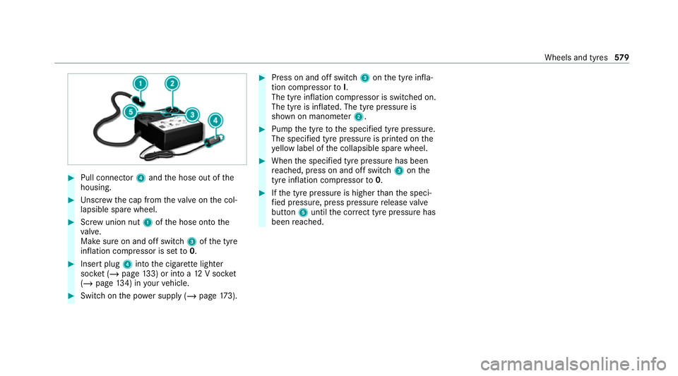
Pull connector 4and the hose out of the
housing. #
Unscr ew the cap from theva lve on the col‐
lapsible spare wheel. #
Screw union nut 1ofthe hose onto the
va lve.
Make sure on and off switch 3ofthe tyre
inflation compressor is set to0. #
Insert plug 4into the cigar ette lighter
soc ket (/ page 133) or into a 12V soc ket
( / page 134) in your vehicle. #
Switch on the po wer supp ly (/ page 173). #
Press on and off swit ch3 onthe tyre infla‐
tion compressor toI.
The tyre inflation compressor is switched on.
The tyre is inflated. The tyre pressure is
shown on manome ter2. #
Pump the tyre tothe specified tyre pressure.
The specified tyre pressure is printed on the
ye llow label of the collapsible spare wheel. #
When the specified tyre pressure has been
re ached, press on and off swit ch3 onthe
tyre inflation compressor to0. #
Ifth e tyre pressure is higher than the speci‐
fi ed pressure, press pressure release valve
bu tton 5until the cor rect tyre pressure has
been reached. Wheels and tyres
57 9
Page 750 of 757
Tu
rn signal lights .....................................1 42
Switching on/off ................................. 14 2
TV ............................................................. 326
Ac tivating ............................................ 497
Ad justing the brightness ..................... 503
Calling up the menu (CI+ module) .......5 04
Information .......................................... 496
Overview ............................................. 498
Picture settings ................................... 503
Setting subtitles .................................. 502
Setting the audio language .................. 502
Showing telete xt .................................. 502
Showing/hiding full screen ................. 499
Te lete xt overview ................................. 502
Vo ice commands (LINGU ATRO NIC) .....3 26
TV channel
Ac tivating/deactivating channel fix ..... 500
Channel fix .......................................... 500
Channel li stove rview .......................... .501
Countr y-specific character set ............ 500
EPG (electronic programme guide) ...... 500
Overview of favo urites ........................ .501
Selecting from thech annel list ............ 499
Selecting from the control menu ......... 499
Selecting from thefa vo urites .............. 499 Selecting in
the bac kground ................ 500
St oring .................................................5 01
Tw o-w ayradios
Fr equencies ......................................... 581
No tes on ins tallation .......................... .580
Tr ansmission output (maximum) .......... 581
Ty re inflation compressor
see TIREFIT kit
Ty re pressure ........................................... 558
Checking (ty repressure monitoring
sy stem) ............................................... 559
No tes ................................................... 557
Re starting the tyre pressure monitor‐
ing sy stem ...........................................5 60
TIREFIT kit .......................................... .539
Ty re pressure monitoring sy stem
(function) ............................................. 559
Ty re pressure table .............................. 558
Ty re pressure moni tor............................. 561
Fu nction .............................................. 559
Ty re pressure moni toring sy stem
Checking the tyre pressure ................. 559
Checking the tyre temp erature ............ 559
Re starting ............................................ 560 Ty
re pressure table ................................. 558
Ty re temp erature
Checking (tyre pressure monitoring
sy stem) ............................................... 559
Ty re pressure monitoring sy stem
(function) ............................................. 559
Ty re tread ................................................. 556
Ty re-change tool kit
Overview ............................................ .568
Ty res
Changing hub caps .............................. 570
Checking ............................................ .556
Che cking the tyre pressure (tyre
pressure monitoring sy stem) ............... 559
Fitting .................................................. 572
Flat tyre ............................................... 537
Inter changing ...................................... 568
MOExtended tyres .............................. .538
Noise ................................................... 556
No tes on fitting ................................... 564
Re moving ............................................. 572
Re placing .................................... 564, 569
Re starting the tyre pressure monitor‐
ing sy stem ...........................................5 60 Index
747