2020 MERCEDES-BENZ GLE COUPE dimensions
[x] Cancel search: dimensionsPage 633 of 757

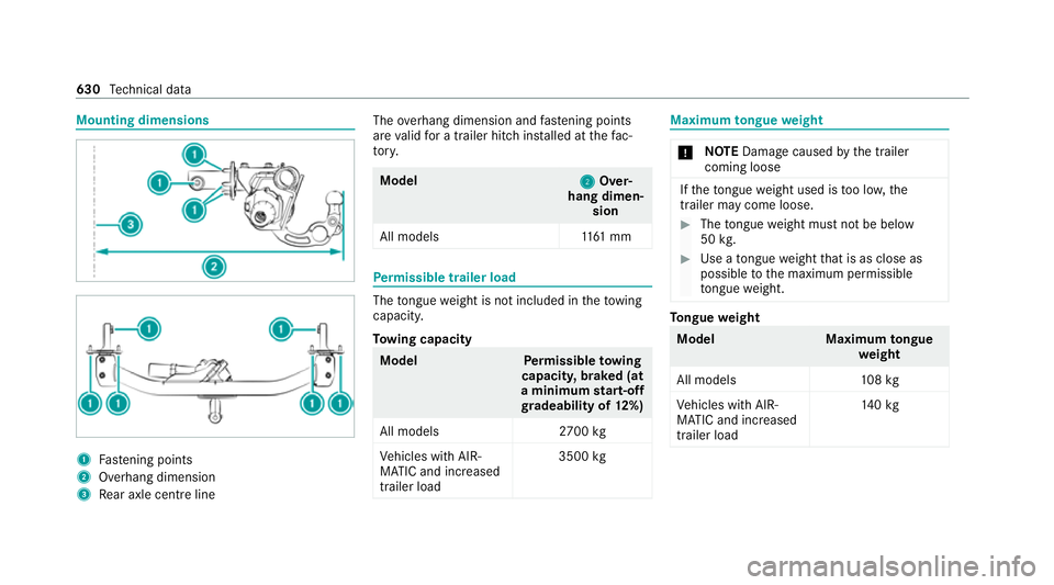
Mounting dimensions
1
Fastening points
2 Overhang dimension
3 Rear axle centre line The
overhang dimension and fastening points
are valid for a trailer hitch ins talled at thefa c‐
to ry. Model
2 2Over‐
hang dimen‐ sion
All model s1 161 mm Pe
rm issible trailer load The
tongue weight is not included in theto wing
capacity.
To wing capacity Model
Perm issible towing
capacit y,braked (at
a minimum start-off
gr adeability of 12%)
All models 2700 kg
Ve hicles with AIR‐
MATIC and increased
trailer load 3500
kg Maximum
tongue weight *
NO
TEDama gecaused bythe trailer
coming loose If
th eto ngue weight used is too lo w,the
trailer may come loose. #
The tongue weight must not be below
50 kg. #
Use a tongue weight that is as close as
possible tothe maximum permissible
to ngue weight. To
ngue weight Model
Maximumtongue
we ight
All models 108kg
Ve hicles with AIR‐
MATIC and increased
trailer load 14
0kg 630
Tech nical da ta
Page 746 of 757

Setting
the suspension le vel (AIR‐
MATIC) ................................................ .249
Setting the suspension le vel (E-
AC TIVE BODY CONTROL) .....................2 58
Suspension see AIRMATIC
see E- ACTIVE BODY CONTROL
Suspension le vel (AIRMATIC)
Setting ................................................ .249
Suspension le vel (E- ACTIVE BODY
CONT ROL)
Setting ................................................ .258
SV HC (substances of very high con‐
cern ).......................................................... .32
Switch-off delay time Exterior ................................................ 14 8
Interior ................................................ 15 0
Synchronisation function Activating/deactivating (MBUX mul‐
timedia sy stem) ................................... 16 3
Switching on/off (control panel) ......... 16 2Sy
stem settings
Ac tivating/deactivating PIN pr otec‐
tion ...................................................... 378
Ac tivating/deactivating voice ampli‐
fi cation torear .................................... .372
Re set function (multimedia sy stem) ....3 80
Setting the dis tance unit ..................... 377
Setting the time and date automati‐
cally ..................................................... 371
Setting the time zone ........................... 371
Setting the time/date form at .............. 371
Switching transmission of theve hicle
position on/off .................................... 372
Sy stem settings
see Blue tooth®
see Data import/export
see Language
see MBUX Touch
see So ftwa reupdate
see Wi-Fi T
Ta ilgate ...................................................... .87
Closing .................................................. 88
HANDS-FREE ACCESS .......................... .90Limiting
the opening angle .................... 92
Opening .................................................87
Opening dimensions ............................6 26
Un locking (emer gency key) .................. .92
Ta ilpipes (Care) ........................................ 531
Ta ke -back of end-of-life vehicles .............. 22
Pr otection of the environment ............... 22
Ta nk content
Ad Blue ®
............................................... 622
Fu el ..................................................... 621
Re ser ve(fuel) ...................................... 621
Te ch nical data
Axle load (trailer operation) ................. 631
Fa stening points (trailer hitch) .............6 30
Information .......................................... 580
Mounting dimensions (trailer hitch) ..... 630
No tes (trailer hitch) ............................. 629
Overhang dimension (trailer hitch) ...... 630
Ra dio equipment appr oval numbers .... 582
To ngue weight .................................... .630
To wing capacity (trailer operation) ...... 630
Ve hicle identification plate ...................6 15
Te lephone ................................ .311, 433, 439
Ac tivating functions du ring a call ........ 443 Index
74 3
Page 749 of 757

Sy
stem limitations ...............................2 84
Tr ailer hitch
Axle load .............................................. 631
Bicycle rack ......................................... 297
Ca re ..................................................... 531
Coupling up/uncoupling a trailer ........ 294
Extending/r etra cting the ball neck ...... 292
Fa stening points ..................................6 30
Gene ral no tes ...................................... 629
Mounting dimensions .......................... 630
No tes .................................................. 292
Overhang dimension ........................... 630
Soc ket ................................................. 294
To ngue weight .................................... .630
To wing capacity .................................. .630
Tr ailer Manoeuv ring Assi st.................. 265
Tr ailer Manoeuvring Assist ..................... 265
Ad justing the articulation angle ........... 266
Fu nction .............................................. 265
St raightening manoeuvre .................... 266
Using .................................................. .266
Tr ailer operation
Ac tive Blind Spot Assi st....................... 288
Ac tive Lane Keeping Assist ................. 289
Bicycle rack ......................................... 297 Coupling up/uncoupling a trailer ........ 294
Extending/r etra cting the ball neck ...... 292
Fo lding the ball coupling in/out
(MBUX multimedia sy stem) ................. 294
No tes .................................................. 292
Soc ket ................................................. 294
Tr ailer stabilisation
Fu nction/no tes .................................... 218
Tr ailer tow hit ch
Fo lding the ball coupling in/out
(MBUX multimedia sy stem) ................. 294
Tr ansfer redve hicle data
Android Auto ....................................... 459
Apple CarPl ay®
.................................... 459
Tr ansmission of theve hicle position
Ac tivating/deactivating ...................... .372
Tr ansmission position display ................19 2
Tr anspo rting
Ve hicle .................................................5 51
Tr im element (Care) ................................ 533
Tr ip
Menu (on-board computer) .................. 307 Tr
ip computer
Displaying ............................................ 307
Re setting ............................................. 308
Tr ip distance ............................................ 307
Displaying ............................................ 307
Re setting ............................................. 308
Tr ip me ter
see Trip dis tance
Tu neIn .......................................................4 81
Calling up ............................................ 481
Calling up thest ation list (category
last selec ted) .......................................4 84
Del eting stations ................................ .484
Logging out ......................................... 484
Overview ............................................. 483
Re gis tering .......................................... 484
Saving stations .................................... 484
Selecting and connecting toast ation
............................................................ .483
Selecting stre am ................................ .484
Setting options .................................... 484
Te rm s of use ........................................4 84
Tu rn signal indicator
see Turn signal lights 74 6
Index
Page 752 of 757

Ve
hicle height ...................................... 626
Ve hicle length ...................................... 626
Ve hicle width ....................................... 626
Wheelbase ...........................................6 26
Ve hicle dimensions ................................. 626
Ve hicle identification number
see VIN
Ve hicle identification plate .....................61 5
EU general operating pe rmit number .. .615
Pa int code ............................................ 61 5
Pe rm issible axle load .......................... .615
Pe rm issible gross mass ...................... .615
VIN ....................................................... 61 5
Ve hicle interior
Cooling or heating (Remo teOnline) ..... 176
Ve hicle key
see Key
Ve hicle le vel
Setting individual wheel control .......... 259
Ve hicle maintenance
see ASS YST PLUS
Ve hicle tool kit ........................................ 538
TIREFIT kit .......................................... .538 To
wing eye .......................................... 552
Ve ntilating
Con venience opening ............................ 94
Ve ntilation
see Climate cont rol
Ve nts
see Air vents
VIN ............................................................ 61 5
Identification plate ............................... 61 5
Seat ..................................................... 61 5
Wi ndsc reen .......................................... 61 5
Vi sion
Demisting windo ws............................. 16 3
Wi ndsc reen heating ............................. 16 5
Vo ice amplification tothere ar
Ac tivating/deactivating ...................... .372
Vo ice control sy stem
see LINGU ATRO NIC W
Wa rning lamps
see Warning/indicator lamps Wa
rning sy stem
see ATA (anti-theft alarm sy stem)
Wa rning triangle
Re moving ............................................ 535
Setting up ............................................ 536
Wa rning/indicator lamp
0025 ABSwarning lamp ...................... 700
004D Brake sy stem warning lamp
(red) .................................................... .697
004D Brake sy stem warning lamp
(yellow) ................................................ 697
ÿ Coolant warning lamp ................ 693
003D Electrical fault warning lamp ...... 695
00B9 Engine diagnosis warning lamp .. 695
00BB ESP®
OFF warning lamp ............ .702
00E5 ESP®
wa rning lamp flashes ........ 701
00E5 ESP®
wa rning lamp lights up ...... 701
00B6 Fuelreser vewarning lamp
lights up .............................................. 696
0075 Restra int sy stem warning lamp .. 691
0076 Seat belt warning lamp flashes .. .691 Index
74 9