2020 MERCEDES-BENZ C-CLASS ESTATE the 12V
[x] Cancel search: the 12VPage 126 of 565
#
When a roof luggage rack isfitted, open
th e panorama sliding sunroof only if this
has been tested and appr oved for
Mercedes-Benz.
The panorama sliding sunroof may be raised
to allow ventilation of theve hicle interior. #
Secure thero of luggage rack tothero of rail‐
ing. #
Obser vethe manufacturer's ins tallation
instructions. Soc
kets Using the
12V so cket Re
quirements:
R Only devices up toa maximum of 180 W
(15 A) are permissible.
Depending on theve hicle equipment, theve hicle
has thefo llowing 12V soc kets:
R Inthestow age compartment in the front
cent reconsole R
Inthestow age compartment in the cent re
console of there ar passenger compartment
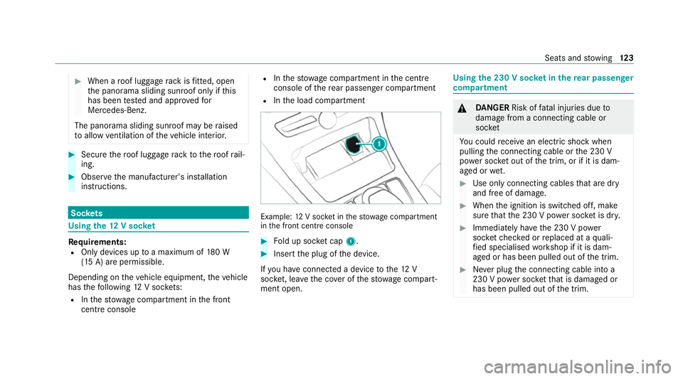
R Inthe load compartment Example:
12V soc ket in thestow age compartment
in the front cent reconsole #
Fold up soc ket cap 1. #
Inse rtthe plug of the device.
If yo u ha veconnected a device tothe12 V
soc ket, le ave the co ver of thestow age compart‐
ment open. Using
the 230 V soc ket in the rear passenger
comp artment &
DANG ER Risk of fata l injuries due to
damage from a connecting cable or
soc ket
Yo u could recei vean electric shock when
pulling the connecting cable or the 230 V
po we r soc ket out of the trim, or if it is dam‐
aged or wet. #
Use only connecting cables that are dry
and free of damage. #
When the ignition is switched off, make
sure that the 230 V po wer soc ket is dr y. #
Immedia tely ha ve the 230 V po wer
soc ketch ecked or replaced at a quali‐
fi ed specialised workshop if it is dam‐
aged or has been pulled out of the trim. #
Never plug the connecting cable into a
230 V po wer soc ketth at is damaged or
has been pulled out of the trim. Seats and
stowing 12 3
Page 194 of 565
re
cei vea notification in the multimedia sy stem
when you swit chon the ignition.
Yo u will recei veinformation about thefo llowing
points:
R The area of theve hicle that may ha vebeen
damaged.
R The forc e of the impact.
The following situations can lead toinadver tent
acti vation:
R The pa rked vehicle is mo ved, e.g. in a two-
st or ey garage.
% Deactivate tow- aw ay protection in order to
pr eve nt inadver tent acti vation. If you deacti‐
va te tow- aw ay protection, collision de tection
will also be deactivated.
Sy stem limits
De tection may be restricted in thefo llowing sit‐
uations:
R theve hicle is damaged without impact, e.g. if
an outside mir ror is torn off or the paint is
damaged byakey
R an impact occurs at low speed R
the electric parking brake is not applied Note
s on parking up theve hicle If
yo u lea vetheve hicle par ked up for longer than
six weeks, it may suf fer dama gethro ugh disuse.
The 12V battery may also be impaired or dam‐
aged byheavy discharging.
% Further information can be obtained at a
qu alified specialist workshop.
* NO
TEPlug-in hybrid #
Obser vethe no tes about the high-volt‐
age battery in the Supplement. Yo u
could otherwise failto recognise dan‐
ge rs. St
andby mode (extension of the star ter bat‐
te ry 's period out of use) St
andby mode function
% This function is not available for all models. If
standby mode is activated, ene rgy loss will be
minimised during extended pe riods of non-oper‐
ation.
St andby mode is characterised bythefo llowing:
R The star ter battery is preser ved.
R The maximum non-operational time appears
inthe media displa y.
R The connection toonline services is inter rup‐
te d.
R The ATA (anti-theft alarm sy stem) is una vaila‐
ble.
R The interior pr otection and tow- aw ay protec‐
tion functions are not available.
R The function for de tecting collisions on a
pa rked vehicle is not available.
If th efo llowing conditions are fulfilled, standby
mode can be activated or deactivated using the
multimedia sy stem:
R The engine is switched off.
R The ignition is switched on.
Exceeding theve hicle's displa yed non-opera‐
tional time may cause inco nvenience, i.e. it can‐ Driving and pa
rking 191
Page 401 of 565
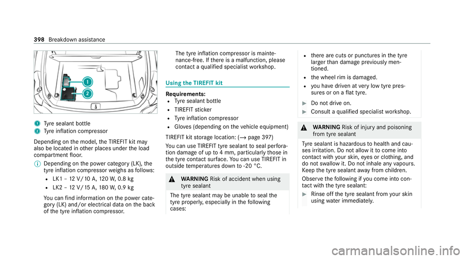
1
Tyre sealant bottle
2 Tyre inflation compressor
Depending on the model, the TIREFIT kit may
also be located in other places under the load
compartment floor.
% Depending on the po wer category (LK), the
tyre inflation compressor weighs as follo ws:
R LK1 – 12V/10 A,120W, 0.8 kg
R LK2 – 12V/15 A,180W, 0.9 kg
Yo u can find information on the po wer cate‐
gory (LK) and/or electrical data on the back
of the tyre inflation compressor. The tyre inflation compressor is mainte‐
nance-free. If
there is a malfunction, please
conta ct aqualified specialist workshop. Using
the TIREFIT kit Re
quirements:
R Tyre sealant bottle
R TIREFIT sticker
R Tyre inflation compressor
R Gloves (depending on theve hicle equipment)
TIREFIT kit storage location: (/ page 397)
Yo u can use TIREFIT tyre sealant toseal per fora‐
tion dama geof up to4 mm, particular lythose in
th e tyre conta ct surface.You can use TIREFIT in
outside temp eratures down to-20 °C. &
WARNING Risk of accident when using
tyre sealant
The tyre sealant may be unable toseal the
tyre properly, especially in thefo llowing
cases: R
there are cuts or punctures in the tyre
lar gerth an damage pr eviously men‐
tioned.
R the wheel rim is dama ged.
R you ha vedriven at very low tyre pres‐
sures or on a flat tyre. #
Do not drive on. #
Consult a qualified specialist workshop. &
WARNING Risk of injury and poisoning
from tyre sealant
Ty re sealant is hazardous tohealth and cau‐
ses ir rita tion. Do not allow it tocome into
contact wi thyour skin, eyes or clo thing, and
do not swallow it. Do not inhale any vapours.
Ke ep the tyre sealant away from children.
Obser vethefo llowing if you come into con‐
ta ct with th e tyre sealant: #
Rinse off the tyre sealant from your skin
using water immediatel y. 398
Breakdown assis tance
Page 403 of 565
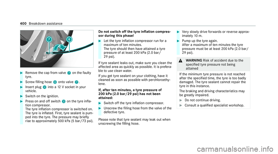
#
Remo vethe cap from valve 7 onthefa ulty
tyre. #
Screw filling hose 8onto valve 7. #
Insert plug 4into a 12V soc ket in your
ve hicle. #
Switch on the ignition. #
Press on and off switch 3onthe tyre infla‐
tion compressor.
The tyre inflation compressor is switched on.
The tyre is inflated. Fir st, tyre sealant is pum‐
ped into the tyre. The pressure may brief ly
ri se toappr oximately 500 kPa (5 bar/73 psi). Do not switch off
the ty reinflation compres‐
sor during this phase! #
Let the tyre inflation compressor runfo r a
maximum of ten minu tes.
The tyre should then ha veattained a tyre
pressure of at least 200 kPa (2.0 bar/
29 psi).
If tyre sealant leaks out, make sure you clean the
af fected area as quickly as possible. It is prefera‐
ble touse clean water.
If yo uge t tyre sealant on your clo thing, ha veit
cleaned as soon as possible with per chloroe thy‐
lene.
If, af terte n minutes, a tyre pressure of
200 kPa (2.0 bar/29 psi) has not been
attained: #
Switch off the tyre inflation compressor. #
Unscr ew thefilling hose from theva lve of the
defective tyre.
Please no tethat tyre sealant may leak out when
unscr ewing thefilling hose. #
Very slowly drive forw ards or reve rse appr ox‐
imately 10m. #
Pump up the tyre again.
Af ter a maximum of ten minu testh e tyre
pressure must be at least 200 kPa (2.0 bar/
29 psi). &
WARNING Risk of accident due tothe
specified tyre pressure not being
attained
If th e minimum tyre pressure is not reached
af te rth e specified time, the tyre is too badly
damaged. The tyre sealant cannot repair the
tyre in this ins tance.
The braking and driving characteristics may
be great lyimpaired. #
Do not continue driving. #
Consult a qualified specialist workshop. 400
Breakdown assis tance
Page 409 of 565
Obser
vethefo llowing points during starting
assis tance and when charging the battery:
R Only use undamaged jump lead/charging
cables with a suf ficient cross-section and
insula tedte rm inal clamps.
R Non- insulated parts of thete rm inal clamps
must not come into con tact wi thother me tal
parts while the jump lead/charging cable is
connected tothe battery/jump-s tart connec‐
tion point.
R The jump lead/charging cable must not
come into contact wi thany parts which may
mo vewhen the engine is running.
R Alw ays make sure that nei ther you nor the
battery is elect rostatically charge d.
R Keep away from fire and naked flames.
R Do not lean overth e batter y.
Obser vethe additional following points when
ch arging the battery:
R Only use battery charge rs tested and
appr oved for Mercedes-Benz.
R Read the battery charge r's operating instruc‐
tions before charging the batter y. Obser
vethe additional following points during
st arting assis tance:
R Starting assis tance may only be pr ovided
using vehicles, batteries or other jump start
devices with a nominal voltage of 12V.
R The vehicles must not touch.
R Vehicles with a petrol engine: jump-start
th eve hicle only when the engine and exhaust
sy stem are cold. St
arting assi stance and charging the12 V
battery Preparing
starting assi stance/charging #
Secure theve hicle byapplying the electric
parking brake. #
Automatic transmission: shiftthe trans‐
mission toposition j. #
Manual transmission: shiftthe transmis‐
sion toneutral. #
Switch off the ignition and all electrical con‐
sumers. #
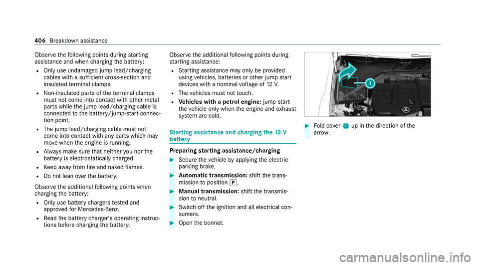
Open the bonn et. #
Fold co ver1 up in the direction of the
ar row. 406
Breakdown assis tance
Page 411 of 565
Re
placing the 12V battery #
Obser vethe no tes on the12 V battery
(/ page 402).
Mercedes-Benz recommends that you ha vethe
12 V battery replaced at a qualified specialist
wo rkshop, e.g. at a Mercedes-Benz Service
Centre.
Obser vethefo llowing no tes if youwa ntto
re place the battery yourself:
R Alw aysre place a faulty bat tery with a battery
which meets the specific vehicle require‐
ments.
The vehicle is equipped with an AGMtech nol‐
ogy battery (Absorbent Glass Mat) or a li th‐
ium-ion batter y.Fu llve hicle functionality is
only guaranteed with an AGM battery or lith‐
ium-ion batter y.Fo r saf etyre asons,
Mercedes-Benz recommends that you on ly
use bat teries which ha vebeen tested and
appr ovedfo ryo ur vehicle byMercedes-Benz.
R Carryove r de tach able parts, such as vent
hoses, elbow fittings or term inal co vers from
th e battery being replaced. R
Make sure that theve nt hose is al ways con‐
nected tothe original opening on the side of
th e batter y.
Fit any existing or supplied cell caps.
Otherwise, gases or battery acid could
escape.
R Make sure that de tach able parts are recon‐
nected in the same way. To
w- starting or towing away Pe
rm itted towing me thods Plug-in
hybrid: be sure toobser vethe no tes in
th e Supplement. You could otherwise failto rec‐
ognise dangers.
* NO
TEDama gefrom auto matic braking If one of
thefo llowing functions is switched
on, theve hicle brakes automatically in cer‐
ta in situations:
R Active Brake Assi st
R Active Dis tance Assi stDISTRONIC R
HOLD function
R Active Parking Assist
To avo id damage totheve hicle, deactivate
th ese sy stems in thefo llowing or similar sit‐
uations: #
During towing #
In a car wash Mercedes-Benz
recommends transporting your
ve hicle in the case of a breakdown, rath er than
to wing it away.
Fo rto wing, use a tow rope or tow bar with bo th
axles on the ground. Do not use tow bar sys‐
te ms.
* NO
TEDama getotheve hicle due to tow‐
ing away incor rectly #
Obser vethe instructions and no tes on
to wing away. 408
Breakdown assis tance
Page 531 of 565
External................................................
.309
Saving (cur rent vehicle position)........... 309
Saving as global favo urit e...................... 309
St oring a map position..........................3 09
Dest ination entry
En tering a 3 wordaddress..................... 299
En tering a POI or address...................... 294
Entering an intermedia tedestination.... 298
Ente ring geo-coordinates...................... 299
Selecting a contact............................... 299
Selecting a POI...................................... 297
Selecting from the map......................... 300
Selecting pr evious destinations............ .297
De tecting inat tentiveness
see ATTENTION ASSIST
Diagnostics connection .............................. 29
Diesel Low outside temp eratures.................... 440
No tes....................................................4 40
Digital Owner's Manual.............................. 20
Digital TV
see TV Dinghy
towing
see Tow- bar sy stem
Dipped beam Changing bulbs...................................... 14 0
Setting................................................... 13 6
DIRECT SELECT le ver
Engaging drive position......................... .176
Engaging neutral.................................... 175
Engaging pa rkposition.......................... 176
Engaging pa rkposition automatically....1 76
Engaging reve rsege ar........................... 175
Fu nction................................................. 174
Display (care) .............................................3 91
Display (multimedia sy stem)
Settings................................................. 280
Display (on-boa rdcompu ter)
Displ ays on the multifunction displa y.... 253
Displ aymessage
Calling up (on-board compu ter)............. 451
No tes..................................................... 451
Display messages ¯ - - - km/h...................................... 477
ç - - - km/h ...................................... 478È
- - - km/h ...................................... 477
# 12V battery See Owner's Man‐
ual......................................................... 492
Û 48 V battery See Owner's Man‐
ual......................................................... 494
: Active Light Sy stem inoperative... 458
¯ AdBlue sy stem fault Emer. op.:
max. XXX mphSt art not poss. in XXX
miles ...................................................... 501
¯ AdBlue sy stem fault Emer‐
ge ncy op. in XXX km See Owner's
Manual.................................................. 500
¯ AdBlue sy stem fault Engine
st art not possible................................. .501
¯ AdBlue sy stem fault See Own‐
er's Manual .......................................... .500
5 Add 1 litre engine oil when
next refuelling....................................... 502
é ATTENTION ASSIST inoperative ....476 528
Index