2020 MERCEDES-BENZ C-CLASS ESTATE display
[x] Cancel search: displayPage 112 of 565
&
WARNING Risk of entrapment when
adjusting the seat with the memory func‐
tion
When the memory function adjusts the seat
or steering wheel, you and other vehicle
occupants – particularly children – could
become trapped. #
During the adjusting process of the
memory function, ensure that no body
parts are in the sweep of the seat or
th esteering wheel. #
If somebody becomes trapped, immedi‐
ately release the memory function posi‐
tion button.
The adjustment process is stopped. &
WARNING Risk of entrapment if the
memory function is activated bychildren
Children could become trapped if they acti‐
va te the memory function, particularly when
unattended. #
Never lea vechildren unat tended in the
ve hicle. #
When leaving theve hicle, alw aysta ke
th eke y with you and lock theve hicle. Yo
u can use the memory function when the igni‐
tion is switched off.
Seat adjustments for up tothre e people can be
st ored and called up using the memory function.
Yo u can sa vesettings forth efo llowing sy stems:
R Seat, backrest and head restra int
R Steering wheel
R Outside mir rors
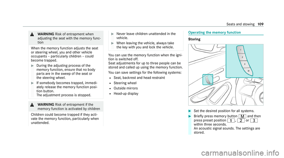
R Head-up display Operating
the memory function St
oring #
Set the desired position for all sy stems. #
Brief lypress memory button Vandthen
press preset position 4,TorU
within thre e seconds.
An acoustic signal sounds. The settings are
st ored. Seats and
stowing 109
Page 116 of 565
Through-loading
feature in there ar ben ch
seat (EAS Y-PA CK Quickfold) Fo
lding there ar seat backrest forw ards &
WARNING Risk of accident if there ar
ben chseat, rear seat and seat backrest
are not engaged
The rear ben chseat, rear seat and seat back‐
re st may fold forw ards, even while theve hi‐
cle is in motion.
R As a result, theve hicle occupant will be
pressed into the seat belt with increased
fo rc e. The seat belt will not be able to
pr otect as intended and could cause
additional injur y.
R Objects or loads in the boot or load com‐
partment cann otbe restra ined bythe
seat backrest. #
Make sure that there ar ben chseat, the
re ar seat and the seat backrest are
engaged before everytrip. If
th e left and right seat backrests are not
engaged and loc ked in place, this will be shown
on the multifunction display on the instrument
clus ter.A wa rning tone will also sound.
If th e cent reseat backrest is not engaged and
loc ked, there d lock verification indicator will be
visible.
Re quirements:
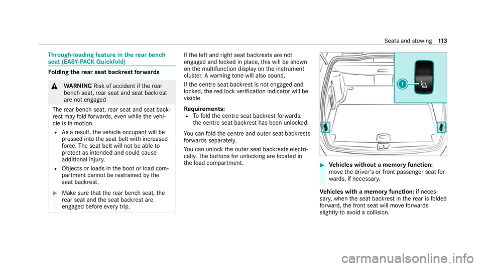
R Tofold the cent reseat backrest forw ards:
th e cent reseat backrest has been unloc ked.
Yo u can fold the cent reand outer seat backrests
fo rw ards separatel y.
Yo u can unlo ckthe outer seat backrests electri‐
cally. The buttons for unlocking are located in
th e load compartment. #
Vehicles without a memory function:
mo vethe driver's or front passenger seat for‐
wa rds, if necessar y.
Ve hicles with a memory function: if neces‐
sar y,when the seat backrest in there ar is folded
fo rw ard, the front seat will mo veforw ards
slightly toavo id a collision. Seats and
stowing 11 3
Page 129 of 565
phone. Pr
otective co vers which are neces‐
sary for wireless charging are excluded. Wire
lessly charging a mobile phone Re
quirements:
R The mobile phone is suitable for wireless
ch arging.
A list of compatible mobile phones can be
fo und at: https://www.mercedes-benz-
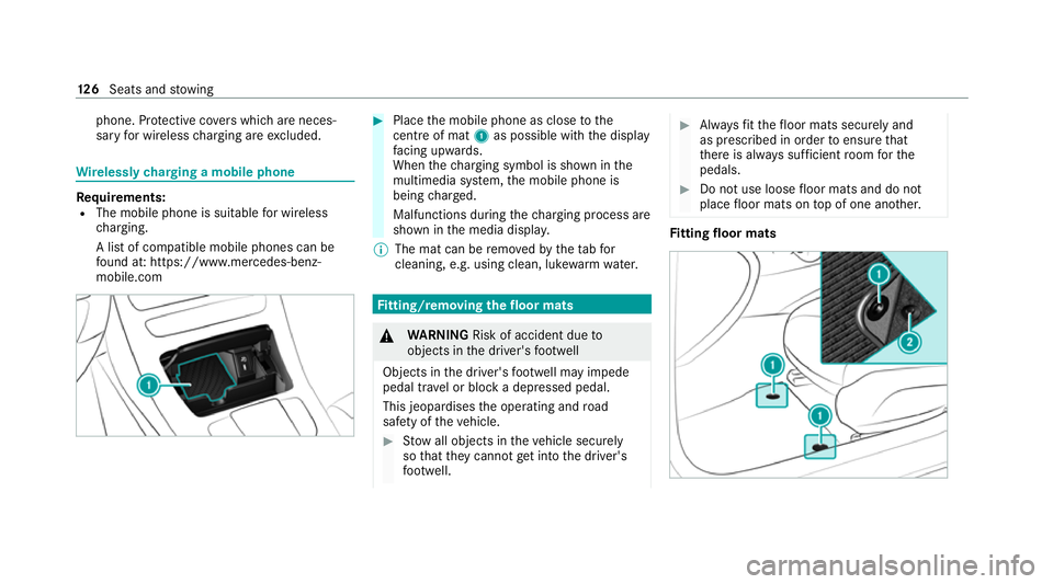
mobile.com #
Place the mobile phone as close tothe
centre of mat 1as possible with th e display
fa cing up wards.
When thech arging symbol is shown in the
multimedia sy stem, the mobile phone is
being charge d.
Malfunctions during thech arging process are
shown in the media displa y.
% The mat can be remo vedby theta bfor
cleaning, e.g. using clean, lu kewa rm wate r. Fi
tting/ removing the floormats &
WARNING Risk of accident due to
objects in the driver's foot we ll
Objects in the driver's foot we ll may impede
pedal tr avel or block a depressed pedal.
This jeopardises the operating and road
saf ety of theve hicle. #
Stow all objects in theve hicle securely
so that they cannot getinto the driver's
fo ot we ll. #
Alw aysfit th efloor mats securely and
as prescribed in order toensure that
th ere is alw ays suf ficient room forthe
pedals. #
Do not use loose floor mats and do not
place floor mats on top of one ano ther. Fi
tting floor mats 12 6
Seats and stowing
Page 139 of 565
ULTRA RANGE Highbeam increases
the bright‐
ness of the cone of light tothe legally permitted
maximum.
Pa rtial high beam uses the high beam toshine
past other road users rath er than dazzling them.
The vehicle in front will be illuminated bythe low
beam.
At speeds below 25 km/h or when there is suf fi‐
cient stre et lighting:
R The partial high beam and the high beam will
be switched off automaticall y.
At speeds greater than 30 km/h:
R If no other road users are de tected, the high
beam will switch on automaticall y.
R Ifot her road users are de tected, the partial
high beam will switch on automaticall y.
At speeds abo ve40 km/h:
R If no other road users are de tected on a
st ra ight road, ULTRA RANGE Highbeam will
be swit ched on automaticall y.
R Ifot her road users are de tected, the partial
high beam will switch on automaticall y.R
If highly reflective signs are de tected, ULTRA
RANGE Highbeam will be switched off au to‐
matical ly.
At speeds greater than appr oximately 50 km/h:
R The headlamp range of the low beam is regu‐
lated automatically based on the dis tance to
ot her road users.
% The sy stem's optical sensor is located
behind the windscreen near theove rhead
control panel.
Switching Adaptive Highbeam Assist Plus
on/off
Switching on #
Turn the light switch tothe à position. #
Switch on the high beam using the combina‐
tion switch.
When the high beam is switched on automat‐
ically in the dar k,the_ indicator lamp on
th e multifunction display will light up. Switching off #
Switch off the high beam using the combina‐
tion switch. Setting
the dipped beam Multimedia sy
stem:
4 Vehicle 5
÷ Light settings
5 Dipped-beams #
Select Left-side traffic orRight-side traffic. Setting
theex terior lighting switch-off delay
time Multimedia sy
stem:
4 Vehicle 5
÷ Light settings
5 Exterior light shut-off #
Set the switch-off delay time. 13 6
Light and sight
Page 141 of 565
Ad
justing the brightness #
Select Brightness . #
Set a brightness value.
Ac tivating the brightness for zones #
Select Brightness zones .#
Activate Oor deacti vate ª the function.
The Display ,Front andRear zones can be set
separately. Setting
the interior lighting switch-off delay
time Multimedia sy
stem:
4 Vehicle 5
÷ Light settings
5 Interior light shut-off #
Set the switch-off delay time. Changing bulbs (only
forve hicles with halo‐
ge n headla mps) Note
s onchanging bulbs &
WARNING Risk of burn s from hot com‐
ponent parts whilst replacing a bulb
Bulbs, lamps and plugs can become very hot
during operation.
When replacing a bulb, you could burn your‐
self on these component parts. #
Allow the component parts tocool
down before replacing the bulb. R
Do not use a bulb if it has been dropped or if
itsglass has been sc ratched. The bulb may
ot herwise explode.
R Do not touch theglass bulb with your bare
hands.
R Protect bulbs from moisture and do not allow
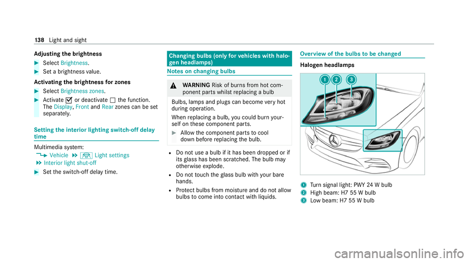
bulbs tocome into contact wi thliquids. Overview of
the bulbs tobe changed Halogen headlamps
1
Turn signal light: PWY 24W bulb
2 High beam: H7 55 W bulb
3 Low beam: H7 55 W bulb 13 8
Light and sight
Page 149 of 565
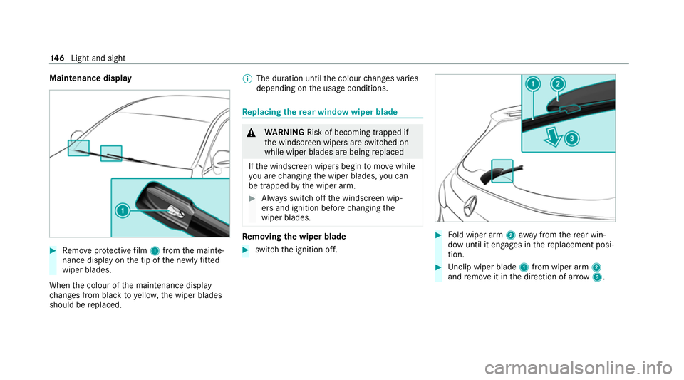
Maintenance display
#
Remo veprotective film 1 from the mainte‐
nance display on the tip of the newly fitted
wiper blades.
When the colour of the maintenance display
ch anges from black to yellow, the wiper blades
should be replaced. %
The duration until the colour changes varies
depending on the usage conditions. Re
placing the rear window wiper blade &
WARNING Risk of becoming trapped if
th e windscreen wipers are switched on
while wiper blades are being replaced
If th e windscreen wipers begin tomo vewhile
yo u are changing the wiper blades, you can
be trapped bythe wiper arm. #
Alw ays switch off the windscreen wip‐
ers and ignition before changing the
wiper blades. Re
moving the wiper blade #
switch the ignition off. #
Fold wiper arm 2away from there ar win‐
dow until it engages in there placement posi‐
tion. #
Unclip wiper blade 1from wiper arm 2
and remo veit in the direction of ar row 3. 14 6
Light and sight
Page 155 of 565
Ve
hicles with a stationary heater: &
swit ches thest ationary heater on/off
(/ page 156)
9 g Switches ai r-re circulation mode on/off
(/ page 154)
A Vehicles with THERMATIC air conditioning
contro l panel: ¿switches A/C function
on/off (/ page152)
Ve hicles with THERMOTRONIC air condition‐
ing contro l panel:_adjusts the air distri‐
bution, right
B w Setsthete mp erature on the front
passenger side Re
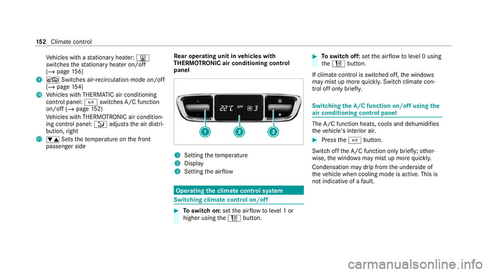
ar operating unit in vehicles with
THERMOTRONIC air conditioning control
panel 1
Setting thete mp erature
2 Display
3 Setting the air flow Operating
the clima tecont rol sy stem Switching clima
tecont rol on/off #
Toswitch on: setthe air flow toleve l 1 or
higher using theH button. #
Toswitch off: setthe air flow toleve l 0 using
th eH button.
If climate control is switched off, the windo ws
may mist up more quickl y.Switch climate con‐
trol off only briefl y. Switching
the A/C function on/off using the
air conditioning control panel The A/C function heats, cools and dehumidi
fies
th eve hicle's interior air. #
Press the¿ button.
Switch off the A/C function only brief ly;ot her‐
wise, the windo wsmay mist up more quickl y.
Condensation may drip from the underside of
th eve hicle when cooling mode is active. This is
not indicative of a fault. 15 2
Climate cont rol
Page 161 of 565
#
Press theu and^ buttons simultane‐
ousl y.
The Îsymbol on there mo tecontrol display
will flash. #
Use the, and. buttons toset the
desired departure time. #
Press theu and^ buttons simultane‐
ousl y.
The new departure time will be stored.
Up tothre e departure times can be stored. #
Toactivate the departu retime: select the
desired departure time and press and hold
th eu button.
The Ísymbol, the departure time and,
depending on the selected departure time,
th e letter A, BorCwill appear on the displa y. #
Todeactivate the departure time: select
th e desired departure time and press and
hold the^ button.
OFF will appear on the displa y. #
Tocheck thest atus of the active station‐
ary heater: briefly press theu button. Switching off immediately #
Press and hold the^ button.
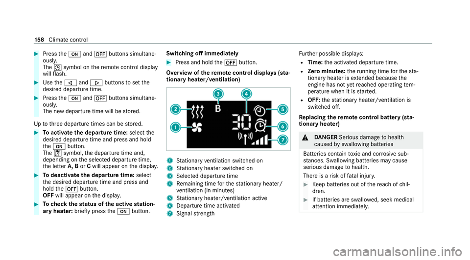
Overview of there mo tecont rol displa ys(sta‐
tiona ryheater/ventilation) 1
Stationary ventilation switched on
2 Stationary heater swit ched on
3 Selected departure time
4 Remaining time forth est ationary heater/
ve ntilation (in minu tes)
5 Stationary heater/ ventilation acti ve
6 Departure time acti vated
7 Signal stre ngth Fu
rther possible displa ys:
R Time: the activated departure time.
R Zero minutes: theru nning time forth est a‐
tionary heater is extended because the
engine has not yetre ached operating tem‐
perature when it is star ted.
R OFF: thest ationary heater/ ventilation is
switched off.
Re placing the remo tecont rol bat tery (sta‐
tiona ryheater) &
DANG ER Serious damage tohealth
caused byswallowing batteries
Batteries contain toxic and cor rosive sub‐
st ances. Swallowing bat teries may cause
serious damage tohealth.
There is a risk of fatal injur y. #
Keep batteries out of there ach of chil‐
dren. #
If batteries are swallo wed, seek medical
attention immediately. 15 8
Climate cont rol