2020 MERCEDES-BENZ C-CLASS ESTATE Open tailgate
[x] Cancel search: Open tailgatePage 123 of 565
#
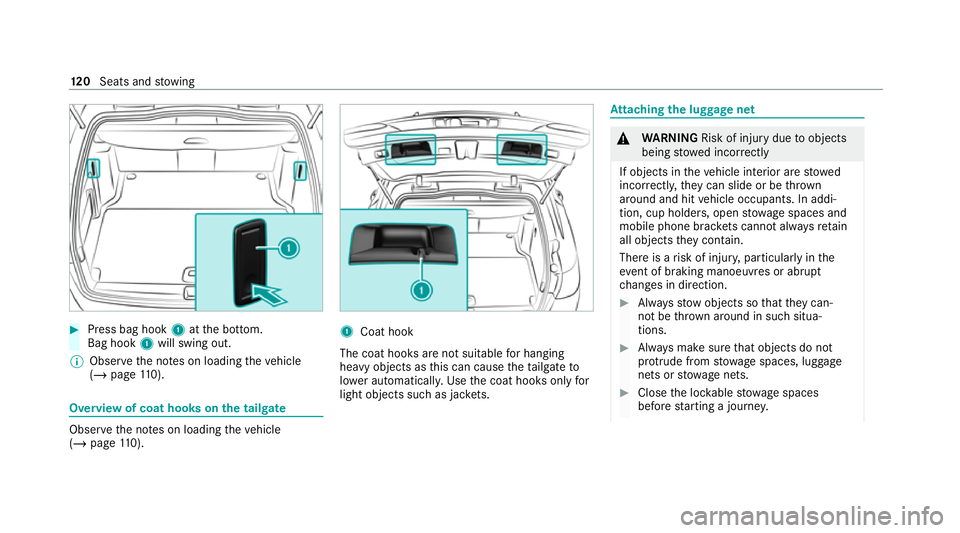
Press bag hook 1atthe bottom.
Bag hook 1will swing out.
% Obser vethe no tes on loading theve hicle
(/ page 110). Overvi
ewof coat hooks on the tailgate Obser
vethe no tes on loading theve hicle
(/ page 110). 1
Coat hook
The coat hoo ksare not suitable for hanging
heavy objects as this can cause theta ilgate to
lo we r auto matical ly. Use the coat hooks only for
light objects such as jac kets. At
taching the luggage net &
WARNING Risk of injury duetoobjects
being stowed incor rectly
If objects in theve hicle interior are stowed
incor rectly, they can slide or be thrown
around and hit vehicle occupants. In addi‐
tion, cup holders, open stowage spaces and
mobile phone brac kets cann otalw aysre tain
all objects they contain.
The reis a risk of injur y,particularly in the
ev ent of braking manoeuvres or abrupt
ch anges in direction. #
Alw aysstow objects so that they can‐
not be throw n around in su chsitua‐
tions. #
Alw ays make sure that objects do not
pr otru de from stowage spaces, luggage
nets or stowage nets. #
Close the loc kable stow age spaces
before starting a journe y.12 0
Seats and stowing
Page 144 of 565
#
Toclose: reinse rtside trim panel1.
Re placing the tail lamp bulbs
Re quirements:
The lighting sy stem is switched off.
The tailgate is open.
Tu rn signal lights:
R PY21W bulb
R The side trim panel is open.
% The bulb forth e turn signal lights can only be
ch anged in vehicles with halogen headlamp s.
Re versing light:
R W16 W bulb Re
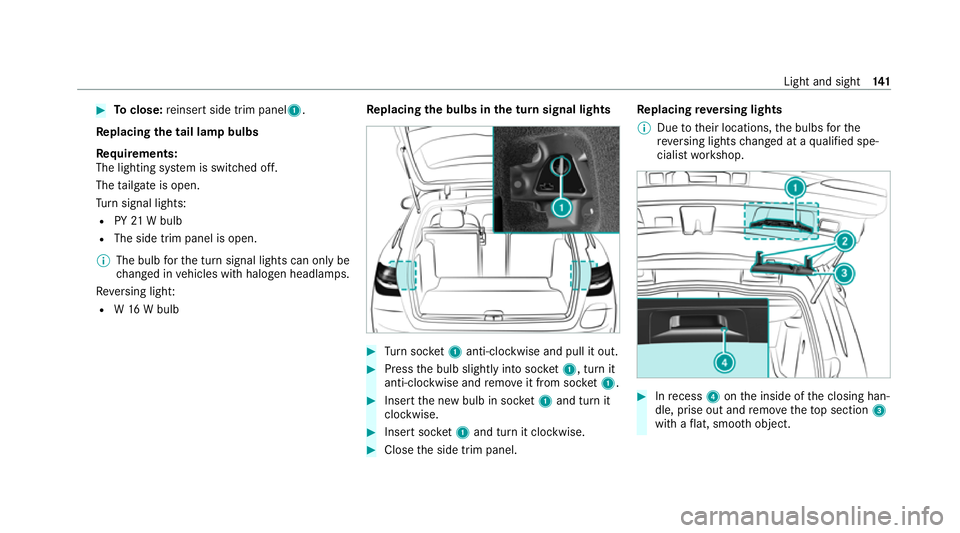
placing the bulbs in the turn signal lights #
Turn soc ket1 anti-clo ckwise and pull it out. #
Press the bulb slightly into soc ket1, turn it
anti-clo ckwise and remo veit from soc ket1. #
Inse rtthe new bulb in soc ket1 and turn it
clo ckwise. #
Insert soc ket1 and turn it clo ckwise. #
Close the side trim panel. Re
placing reve rsing lights
% Due totheir locations, the bulbs forthe
re ve rsing lights changed at a qualified spe‐
cialist workshop. #
Inrecess 4onthe inside of the closing han‐
dle, prise out and remo vetheto p section 3
with a flat, smo oth object. Light and sight
141
Page 146 of 565
#
If not, remo vethe missing me tal clips from
th e panel apertures in theta ilgate and inse rt
th em in the cor responding positions. #
Take trim 7and connect plug connector 6
to the sur round lighting.
The sur round lighting does not illuminate
until theta ilgate has been closed and then
opened again. #
Vehicles with EASY -PAC K tailgate: insert
th e plug connector forth e switch in thetop
ri ght of the trim. #
Vehicles with electric fold-out trailer tow
hit ch: inse rtthe plug connector forthe
switch in theto p left of the trim. #
Position trim 7and engage it in place by
ge ntly tapping it with your hand, starting
from the outside. #
Clip in the lo wer section of handle 1again. #
Insert and engage the upper section of han‐
dle 3into lo wer section 1. Wi
ndscreen wipers and windscreen washer
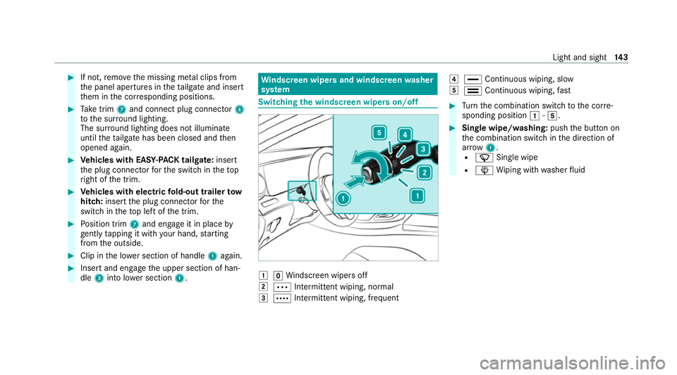
sy stem Switching
the windscreen wipers on/off 1
gWindsc reen wipers off
2 Ä Intermittent wiping, normal
3 Å Intermittent wiping, frequent 4
° Continuous wiping, slow
5 ¯ Continuous wiping, fast #
Turn the combination switch tothe cor re‐
sponding position 1-5. #
Single wipe/washing: pushthe button on
th e combination switch in the direction of
ar row 1.
R í Single wipe
R î Wiping with washer fluid Light and sight
14 3
Page 232 of 565
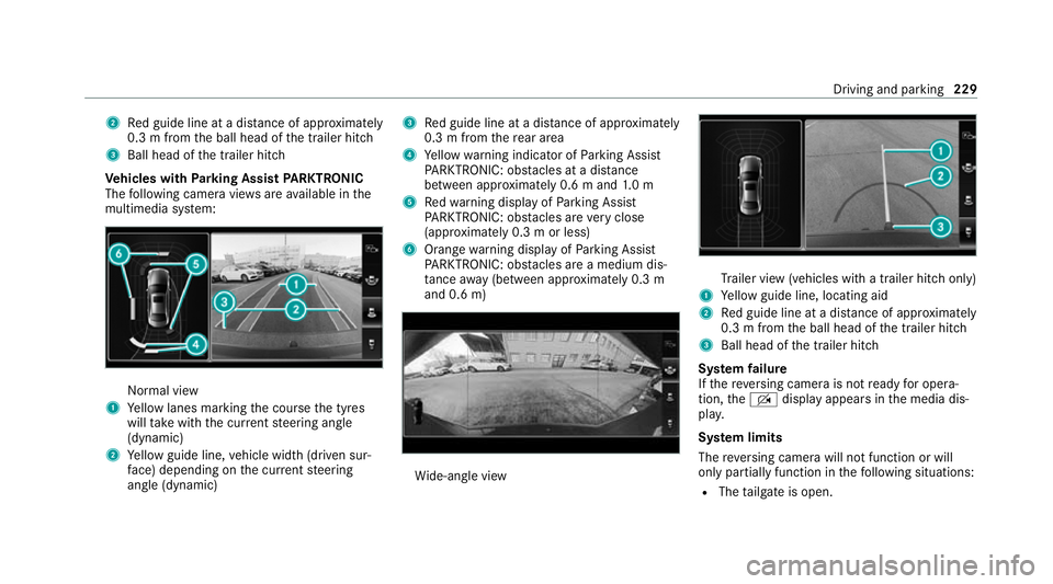
2
Red guide line at a dis tance of appr oximately
0.3 m from the ball head of the trailer hitch
3 Ball head of the trailer hitch
Ve hicles with Parking Assist PARKTRONIC
The following camera vie wsare available in the
multimedia sy stem: Normal view
1 Yellow lanes marking the course the tyres
will take with the cur rent steering angle
(dynamic)
2 Yellow guide line, vehicle width (driven sur‐
fa ce) depending on the cur rent steering
angle (dynamic) 3
Red guide line at a dis tance of appr oximately
0.3 m from there ar area
4 Yellow warning indicator of Parking Assist
PA RKTRONIC: obstacles at a dis tance
between appr oximately 0.6 m and 1.0 m
5 Redwa rning display of Parking Assist
PA RKTRONIC: obstacles are very close
(appr oximately 0.3 m or less)
6 Orange warning display of Parking Assist
PA RKTRONIC: obstacles are a medium dis‐
ta nce away (between appr oximately 0.3 m
and 0.6 m) Wi
de-angle view Tr
ailer view (vehicles with a trailer hit chonly)
1 Yellow guide line, locating aid
2 Red guide line at a dis tance of appr oximately
0.3 m from the ball head of the trailer hitch
3 Ball head of the trailer hitch
Sy stem failure
If th ere ve rsing camera is not ready for opera‐
tion, theq display appears in the media dis‐
pla y.
Sy stem limits
The reve rsing camera will not function or will
only partially function in thefo llowing situations:
R The tailgate is open. Driving and parking
229
Page 235 of 565
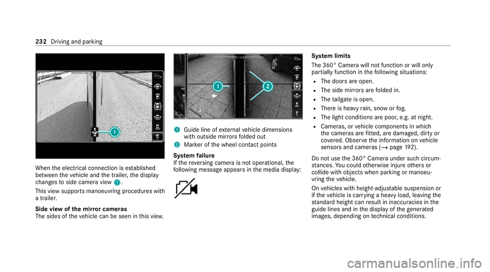
When
the electrical connection is es tablished
between theve hicle and the trailer, the display
ch anges toside camera view 1.
This view supports manoeuvring procedures with
a trailer.
Side view of the mir ror cameras
The sides of theve hicle can be seen in this vie w. 1
Guide line of extern al vehicle dimensions
with outside mir rors folded out
2 Marker of the wheel conta ct points
Sy stem failure
If th ere ve rsing camera is not operational, the
fo llowing message appears in the media display: Sy
stem limits
The 360° Camera will not function or will only
partially function in thefo llowing situations:
R The doors are open.
R The side mir rors are folded in.
R The tailgate is open.
R There is heavy rain, snow or fog.
R The light conditions are poor, e.g. at night.
R Cameras, or vehicle components in which
th e cameras are fitted, are dama ged, dirty or
co vered. Obser vethe information on vehicle
sensors and cameras (/ page192).
Do not use the 360° Camera under such circum‐
st ances. You could otherwise injure others or
collide with objects when parking or manoeu‐
vring theve hicle.
On vehicles with height-adjus table suspension or
if th eve hicle is car rying a heavy load, leaving the
st andard height can result in inaccuracies in the
guide lines and in the display of thege nerated
ima ges, depending on tech nical conditions. 232
Driving and pa rking
Page 249 of 565
Coupling/uncoupling a trailer
&
WARNING Risk of injury fromtheve hicle
le ve l being changed
Ve hicles with le vel control sy stem: the
ve hicle le vel may be changed unin tentional ly,
e.g. by ot her persons. You may become trap‐
ped if you couple up or uncouple a trailer
while theve hicle le vel is changing. In addi‐
tion, other people could become trapped if
th eir limbs are between theve hicle body and
th e tyres or underneath theve hicle.
When coupling up or uncoupling a trailer,
make sure that: #
The doors or tailgate are not opened or
closed. #
You do not initiate the le vel control sys‐
te m and do not operate theDY NA MIC
SELECT switch. #
Do not lock or unlock theve hicle. Re
quirements:
R The ball neck is extended and engaged in a
secu rely loc ked position. Tr
ailers with a 7-pin plug can be connec tedto
th eve hicle with thefo llowing adap ters:
R Adapter plug
R Adapter cable
The trailer will be cor rectly de tected bytheve hi‐
cle only if thefo llowing conditions are me t:
R The trailer is connected cor rectl y.
R The trailer lighting sy stem is in working
order.
The functions of thefo llowing sy stems will be
af fected bya cor rectly connected trailer:
R ESP ®
trailer stabilisation
R Active Lane Keeping Assist
R Parking Assist PARKTRONIC
R Active Parking Assist
R Blind Spot Assist or Active Blind Spot Assi st
R Drive AwayAssi st
R Cross Traf fic Alert
R Reversing camera
R 360° camera R
AIRMATIC
Coupling up a trailer
* NO
TEDama getothest ar ter battery due
to full discharge Charging
the trailer battery using the po wer
supply of the trailer can damage thest ar ter
batter y. #
Do not use theve hicle's po wer supply
to charge the trailer batter y. #
Remo vethe co ver cap from the ball head and
st ore it in a safe place. #
Position the trailer on a le vel sur face behind
th eve hicle and couple it up totheve hicle. 246
Driving and pa rking
Page 468 of 565
Display messages
Possible causes/consequences and M MSolutions #
Neverre lease the bonn etwhen driving. #
Before every trip, ensure that the engine bonn etis loc ked. #
Stop theve hicle immediately, paying attention toroad and traf fic conditions. #
Close the bonn et.
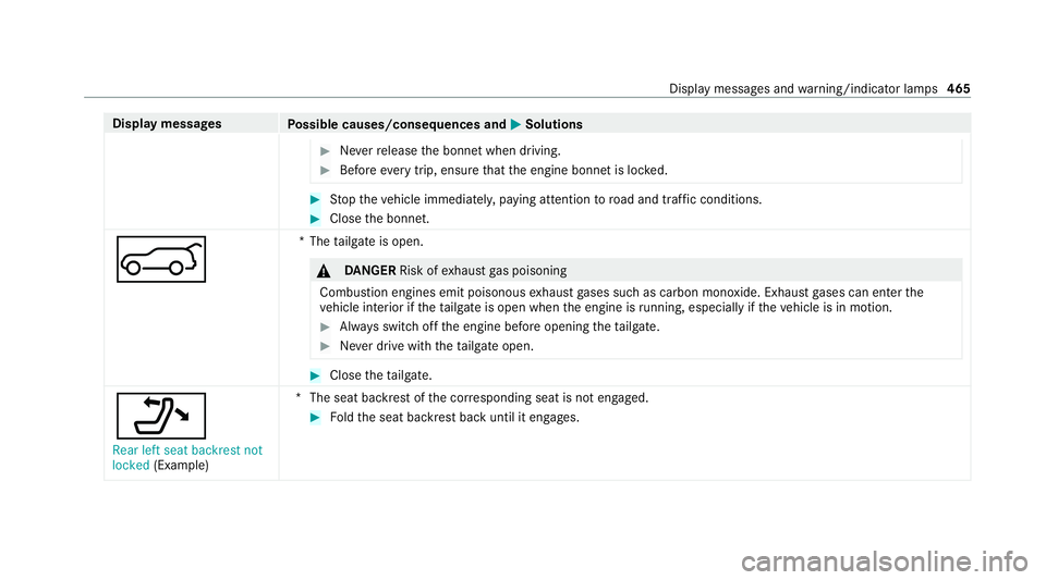
A *T
hetailgate is open. &
DANG ER Risk of exhaust gas poisoning
Combustion engines emit poisonous exhaust gases such as carbon monoxide. Exhaust gases can enter the
ve hicle interior if theta ilgate is open when the engine is running, especially if theve hicle is in motion. #
Alw ays switch off the engine before opening theta ilgate. #
Never drive with theta ilgate open. #
Close theta ilgate.
_ Rear left seat backrest not
locked (Example) *T
he seat backrest of the cor responding seat is not engaged. #
Foldthe seat backrest back until it engages. Display messages and
warning/indicator lamps 465
Page 529 of 565
CI+ module
Calling up a men u.................................. 374
Inserting the smart card........................3 74
City lighting .............................................. .133
Cleaning see Care
Climate control Activating/deactivating the A/C
function (contro l panel)........................ .152
Ac tivating/deactivating the A/C
function (MBUX multimedia sy stem)..... 15 3
Ac tivating/deactivating the synchro‐
nisation function (contro l panel)............15 3
Ac tivating/deactivating the synchro‐
nisation function (multimedia sy stem)... 154
Air-reci rculation mode...........................1 54
Au tomatic control.................................. 15 3
Climate style function............................1 53
Demisting the windscreen..................... 151
Demi sting windo ws............................... 154
Fr ont air vents....................................... 16 0
Inserting/removing theflacon (fra‐
gr ance sy stem)...................................... 15 5
Ionisation............................................... 154
No te....................................................... 151Re
ar air vents........................................ 16 0
Re sidual heat......................................... 154
Setting rear climate control (multi‐
media sy stem)....................................... 15 3
Setting the air distribution..................... 151
Setting the air flow ................................. 151
Setting the climate style........................ 15 3
Setting the fragrance sy stem.................1 54
Setting theve hicle interior temp era‐
ture........................................................ 151
St ationary heater/ ventilation................ 15 6
Switching on/of f................................... 15 2
Switching there ar wind owheater
on/off.................................................... 151
THERMATIC contro l panel...................... 151
THERMOTRONIC contro l panel..............151
Ve ntilating theve hicle (con venience
opening).................................................. 88
Climate style
Fu nction................................................ 15 3
Setting................................................... 15 3
Coat hook .................................................. .120
Coat hook on the tailgate........................ .120 Cock
pit
Overview................................................... 6
Co ffee cup symbol
see ATTENTION ASSIST
Collision de tection (pa rked vehicle) ........ 19 0
COMAND Online see Multimedia sy stem
COMAND Touch
Managing devices.................................. 285
Combination switch .................................. 13 0
Combined luggage co ver and net
At tach ing tothere ar seat backrest........1 17
Ins talling/ removing............................... 11 7
Compass..................................................... 318
Compu ter
see On-board computer
Connection status
Displ aying.............................................. 349
Overview............................................... 349
Connectivity Swit ching transmission of theve hicle
position on/off...................................... 282 526
Index