2020 MERCEDES-BENZ AMG GT R-ROADSTER ABS
[x] Cancel search: ABSPage 12 of 441
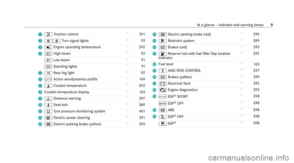
1
Õ Traction control →
391
2 #! Turn signal lights →
92
3 p Engine operating temp erature →
392
4 K High beam →
92
L Low beam →
91
T Standing lights →
91
5 R Rear fog light →
92
6 | Active ae rodynamics profile →
14 9
7 ÿ Coolant temp erature →
392
8 Coolant temp erature display →
16 3
9 L Distance warning →
397
A ü Seat belt →
389
B h Tyre pressure monitoring sy stem →
401
C Ù Electric po werst eering →
391
D ! Electric pa rking brake (yellow) →
395 E
! Electric parking brake (red) →
395
F 6 Restra int sy stem →
389
G J Brakes (red) →
395
H 8 Reser vefuel with fuel filler flap location
indicator →
392
I Fuel le vel →
16 3
J ä AMG RIDE CONTROL →
397
K J Brakes (yellow) →
395
L # Electrical fault →
392
M ; Engine diagnostics →
392
N Æ ESP®
SPORT →
398
¤ ESP®
OFF →
398
O ! ABS →
398
P å ESP®
OFF →
398
÷ ESP®
→
398 At
aglance – Indicator and warning lamps 9
Page 23 of 441
#
Ifth ere is damage, consult a qualified
specialist workshop immediately. *
NO
TEDama getotheve hicle In
thefo llowing situations, in particular, there
is a risk of damage totheve hicle:
R theve hicle becomes grounded, e.g. on a
high kerb or an unpa vedro ad
R theve hicle is driven toofast over an
obs tacle, e.g. a kerb, speed bump or pot‐
hole
R a heavy object strike sth e underbody or
ch assis components
In situations such as this, the body, the
underbody, chassis components, wheels or
tyres could be damaged without the damage
being visible. Components damaged in this
wa y can unexpecte dlyfail or, in the case of
an accident, may not absorb the loads that
arise as intended.
If th e underbody panelling is damaged, flam‐
mable materials such as lea ves, grass or twigs can collect between
the underbody and
th e underbody panelling. These materials
may ignite if they come into contact wi thhot
parts on theex haust sy stem. #
Have theve hicle checked and repaired
immediately at a qualified specialist
wo rkshop.
or #
If driving saf ety is impaired while con‐
tinuing your journe y,pull over and stop
th eve hicle immediately in accordance
with the traf fic conditions, and contact
a qu alified specialist workshop. Declaration of conformity
Electromagnetic compatibility
The electromagnetic compatibility of
theve hicle
components has been checked and certified
according tothe cur rently valid version of Regu‐
lation UN R10. Wire
lessvehicle comp onents Fo
r EU and EF TAcount ries onl y:
The following information applies toall wireless
components of theve hicle and of the informa‐
tion sy stems and communication devices inte‐
grated into theve hicle:
The wireless components of this vehicle comply
with the basic requ irements and all other rele‐
va nt conditions of Directi ve2014 /53/EU. Yo u
can obtain fur ther information from a Mercedes-
Benz Service Centre.
Brazil onl y:
No teon the two-w ayradio sy stems in theve hi‐
cle:
These sy stems are not pr otected from harmful
inter fere nce and mu stnot cause inter fere nce in
duly appr oved sy stems.
Nigeria onl y:
Connection and use of the wireless communica‐
tion equipment in this vehicle are permitted by
th e Nigerian Communications Commission. 20
General no tes
Page 58 of 441

The indicator lamps display
thest atus of the
front passenger airbag:
R Ifth e sensor sy stem forth e automatic child
seat recognition on the front passenger seat
has de tected a special Mercedes-Benz child
re stra int sy stem with a transponder, the
PA SSENGER AIR BAG OFF indicator lamp
lights up. The front passenger airbag is disa‐
bled. It will then not be deplo yed in theeve nt
of an accident.
R If an occupant is de tected on the front
passenger seat, thePA SSENGER AIR BAG ON
indicator lamp lights up. The front passenger
airbag is enabled. The PASSENGER AIR BAG
OFF indicator lamp does not light up. If, in
th eeve nt of an accident, all deploy ment cri‐
te ria are met, the front passenger airbag is
deplo yed.
Obser vethefo llowing information:
R Suitability of seats for attaching belt-secu red
ch ild restra int sy stems (/ page57)
R Forw ard-facing and rear wa rd-facing child
re stra int sy stems on the front passenger seat
(/ page 57) Securing
thech ild restra int sy stem with the
seat belt Note
s onthe suitability of seats for attach‐
ing belt-secured child restra int sy stems
Note s onchild restra int sy stems on the front
passenger seat
R If it is absolutely necessary foryo uto fit a
ch ild restra int sy stem tothe front passenger
seat, be sure toobser vethe information on
ch ild restra int sy stems on the front
passenger seat (/ page 58).
R Obser vethe specific instructions forthe
re ar wa rd-facing and forw ard-facing child
re stra int sy stems. If the front passenger seat
is occupied, ensure, bo thbefore and during
th e journe y,that thest atus of the front
passenger airbag is cor rect forth e cur rent
situation (/ page 44).
Fr ont passenger seat (vehicles without AMG
buc ket seats)
We ight category 0: up to10 kg
Fr ont passenger airbag enabled X Fr
ont passenger airbag disabled 1
X
We ight category 0+: up to13 kg
Fr ont passenger airbag enabled X
Fr ont passenger airbag disabled 1
X
We ight category I: 9 to18 kg
Fr ont passenger airbag enabled U, L
Fr ont passenger airbag disabled 1
U, L
We ight category II: 15to25 kg
Fr ont passenger airbag enabled U, L
Fr ont passenger airbag disabled 1
U, L
We ight category III: 22 to36 kg
Fr ont passenger airbag enabled U, L
Fr ont passenger airbag disabled 1
U, L Occupant saf
ety55
Page 66 of 441
#
Insert the front tabs of battery compartment
co ver1 into the housing and then press to
close it. #
Insert emergency key2 into thekey. Problems with
thekey Yo
u can no lon ger lo ckor unlock theve hicle
Po ssible causes:
R The key bat tery iswe ak or dischar ged.
R The key is faulty. #
Check the battery using the indicator lamp
and replace if necessary (/ page 62).#
Use the emer gency keyto lock or unlock
(/ page 61). #
Have theke ych ecked at a qualified specialist
wo rkshop.
There is inter fere nce from a po werful radio
signal source
The key function is impaired by,fo rex ample:
R high voltage po wer lines
R mobile phones R
electronic devices (No tebooks, Tablets)
R shielding due tome tal objects or induction
loops for electrical gatesystems or auto‐
matic bar riers #
Make sure that there is a suf ficient dist ance
between theke y and the po tential sou rce of
inter fere nce.
Yo u ha velost a key #
Have theke y deactiva ted at a qualified spe‐
cialist workshop. #
If necessar y,ha ve the mechanical lock
re placed as well. Doors
Note
s onthe additional door lock The additional door lock is only
available for
ve hicles forth eUni ted Kingdom. &
WARNING Risk of injury topersons
inside theve hicle when the additional
door lock is activated
If th e additional door lock is activated, the
doors can no longer be opened from the
inside. #
Never lea vepersons, in particular chil‐
dren, unat tended in theve hicle. #
Ifth ere are persons in theve hicle, do
not activate the additional door loc k. The additional door lock is automatically activa‐
te
d in thefo llowing situations:
R The vehicle is loc ked using thekey.
R The vehicle is loc ked using KEYLESS-GO.
If th eve hicle has been loc ked via Mercedes me
connect, the additional door lock is not activa‐
te d.
If th e additional door lock is activated, the doors
cann otbe opened from the inside.
% After locking you can issue a signal with the
horn. Opening and closing
63
Page 117 of 441
Brake sy
stem Note
s onthe brake sy stem
The brake sy stem of your vehicle is designed for
heavy loads. Therefore, there may be noise when
braking. The loads in the entire brake sy stem
which occur when driving on a racetrack are sig‐
nificantly grea terth an those during normal oper‐
ation.
The increased brake forc es and temp eratures
when driving on a racetrack inhe rently lead to
inc reased wear of the brake sy stem.
Check the condition and geometry of the brake
co ver plate before using theve hicle on a race‐
trac k.
Obser vethe information on the cooling of com‐
ponents which are subject tostra in when oper‐
ated on a racetrack (/ page 113).
Braking with ABS
Re peated hard braking within the ABS control
ra nge causes higher temp eratures in the brake
sy stem than controlled braking shortly before
th e ABS control limit. Brakepad
wear
The inner and outer brakepads may also suf fer
"tapered wear". This could lead topoor pedal
fe el. Therefore, you must also check the condi‐
tion of the brakepads before and af ter use on a
ra cetrack as part of astandard check forwe ar.
Brake discs
Obse rveth e information on the cooling of com‐
ponents which are subject tostra in in racetrack
ope ration (/ page 113).
Depending on theve hicle's equipment, the AMG
ceramic high-per form ance composite braking
sy stem is fitted in your vehicle. The assessment
of we ar must therefore be car ried out using a
special measurement procedure. The brakes are
measured using the cur rent condition of the
ceramic composite material as a criteria for
assessing thewe ar ins tead of assessing the
re sidual thickness.
Depending on the type of brake disc, thefo llow‐
ing are combinations used tomeasu rethewe ar
of the brake discs:
R Carbon-ceramic brake disc -
Visual assessment of the brake disc for
mechanical dama ge
- Wear measurement using the indicator
fi eld me thod; alternatively using the Pro‐
ceq Carbo teq®
measu ring device (e.g. in
th e AMG Performance Center or at AMG
Tr ackda ys)
R Grey cast iron brake disc
- Visual check
- Crack test
- Wearthickness test
The ventilation holes on gr eycast iron friction
ri ngs of standard brake discs in particular could
become bloc kedby brake dust. Therefore, check
th eve ntilation holes be fore using theve hicle on
a ra cetrack and clean them if necessar y.If nec‐
essar y,also clean the drilled holes.
Brake fluid
Che ckthefo llowing properties of the brake fluid
before each use on a racetrack:
R Boiling point
R Fill le vel 11 4
Driving and pa rking
Page 135 of 441
Some driving and driving safe
ty systems use
cameras and sensors tomonitor the area in
front of, behind or next totheve hicle.
Ke ep the areas around the sensors and cameras
free of dirt, ice or slush (/ page 299). The cam‐
eras and sensors must not be co vered, forex am‐
ple bybicycle rack s, overhanging loads, sticke rs,
fo il or foils toprotect against stone chipping.
Ad ditional licence plate brac kets can impair the
function of the ultrasonic sensors, in particular.
In theeve nt of damage or a severe impact in the
area of the sensors, ha vethe function of the
sensors checked at a qualified specialist work‐
shop. Ha vedamage or stone chipping in the area
of the cameras repaired at a qualified specialist
wo rkshop. If the sensors or cameras are dam‐
aged, some driving sy stems and driving saf ety
sy stems may no longer function proper ly.Overview of driving sy
stems and driving
saf ety sy stems R
ABS (Anti-lo ckBra king System)
(/ page 132)
R BAS (Bra keAssist System) (/ page132) R
ESP ®
(Electronic Stability Program)
(/ page 133)
R EBD ( Electronic Brakeforc eDistribution)
(/ page 135)
R Active Brake Assi st (/ page 135)
R Adaptive Brake Lights (/ page138)
R Cruise control (/ page 138)
R Limi ter (/ page139)
R Active Dis tance Assi stDISTRONIC
(/ page 141)
R Hill Start Assist (/ page144)
R HOLD function (/ page145)
R RACE START (/ page 146)
R AMG RIDE CONTROL (/ page150)
R Front and reve rsing camera (/ page154)
R ATTENTION ASSIST (/ page156)
R Traf fic Sign Assi st (/ page 157)
R Blind Spot Assi st (/ page 159)
R Lane Keeping Assist (/ page160) Fu
nction of ABS The Anti-lock Brake Sy
stem (ABS) regulates the
brake pressure in critical driving situations:
R During braking, e.g. at full brake application
or insuf ficient tyre traction, the wheels are
pr eve nted from lock ing.
R Vehicle steerability while braking is ensured.
If ABS inter venes when braking, you will feel a
pulsing in the brake pedal. The pulsating brake
pedal can be an indication of hazardous road
conditions and can ser veas a reminder totake
ex tra care while driving. Fu
nction of BAS The Brake Assist Sy
stem (BAS) supports your
eme rgency braking situation with additional
brake forc e.
If yo u depress the brake pedal quickl y,BA S is
acti vated:
R BAS au tomatically boosts the brake pres‐
sure.
R BAS can sho rten the braking dis tance. 13 2
Driving and pa rking
Page 136 of 441
R
ABS pr events the wheels from locking.
The brakes will function as usual once you
re lease the brake pedal. BAS is deactivated. Fu
nctions of ESP ®
(Electronic Stability Pro‐
gr am) &
WARNING Risk of skidding if ESP ®
is
malfunctioning
If ESP ®
is malfunctioning, ESP ®
cannot car ry
out vehicle stabilisation. In addition, other
driving saf ety sy stems are switched off. #
Drive on carefull y. #
Have ESP ®
ch ecked at a qualified spe‐
cialist workshop. Yo
u can select between thefo llowing modes of
ESP ®
:
R ESP ®
ON
R ESP ®
SPO RT
R ESP ®
OFF Charac
terist ics when ESP ®
is activated
ESP ®
monitors and impr oves driving stability and
traction, particular ly inthefo llowing situations:
R When pulling away on wet or slippe rycar ria‐
ge wa ys.
R When braking.
ESP ®
can stabilise theve hicle byinter vening in
th efo llowing ways:
R One or more wheels are braked.
R The engine output is adap ted according to
th e situation.
ESP ®
is activated every time the engine is star‐
te dre ga rdless of whe ther ESP ®
wa s in ESP ®
SPORT or deactivated before the engine was
switched off.
If th e÷ ESP®
wa rning lamp flashes in the
instrument clus ter,one or se veralve hicle wheels
has reached its grip limit:
R Adapt the driving style to suit the pr evailing
ro ad and weather conditions. R
Do not deactivate ESP ®
under any circum‐
st ances.
R Onlydepress the accelera tor pedal as far as
is necessar y.
Cha racteristics of ESP ®
SPORT &
WARNING Risk of skidding if ESP ®
SPORT is used incor rectly
When you activate ESP ®
SPOR T,there is an
increased risk of skidding and having an acci‐
dent. #
Activate ESP ®
SPO RTonly in the cir‐
cums tances described belo w. When ESP
®
SPORT is activated, theå and
Æ warning lamps light up continuously in the
instrument clus ter.
Select ESP ®
SPORT when theve hicle's own
ove rste ering and under steering characteristics
are desired, e.g. on designated roads.
Driving with ESP ®
SPO RTor with ESP ®
deactiva‐
te dre qu ires an extreme ly qualified and experi‐
enced driver. Driving and parking
13 3
Page 164 of 441
Sensitivity of Lane
Keeping Assist
Wi th th eSt andard or Adaptive setting, you can
influence when thewa rning vibration of Lane
Ke eping Assist take s place.
In bo th theSt andard and Adaptive settings, no
wa rning vibration occurs in thefo llowing situa‐
tions:
R You ha veswitched on the turn signal indica‐
to r.
R A driving sa fety sy stem inter venes, su chas
ABS, BAS or ESP ®
.
In theAd aptive setting, there will also be no
wa rning vibration in thefo llowing situations:
R The vehicle is accelerated or braked consid‐
erably.
R Yousteer actively, e.g. swer vetoavo id an
obs tacle or change lane quickl y.
R You cut the corner on a sharp bend. Ve
hicle towing instructions
The vehicle is not suitable forth e use of tow bar
sy stems that are used forflat towing or ding hyto
wing, forex ample. Attach ing and using tow bar
sy stems can lead todamage on theve hicle.
When you are towing a vehicle with tow bar sys‐
te ms, safe driving characteristics cannot be
guaranteed forth eto wing vehicle or theto wed
ve hicle. The vehicle-trailer combination may
swer vefrom side toside. Comply with the per‐
mitted towing me thods (/ page315) and the
instructions forto wing with bo thaxles on the
ground (/ page315). Driving and pa
rking 161