2020 MERCEDES-BENZ AMG GT R-ROADSTER lights
[x] Cancel search: lightsPage 96 of 441
High beam
#
Toswitch on: turnthe light switch tothe
L orà position. #
Push the combination switch be yond the
point of resis tance in the direction of ar row
1 .
When the high beam is activated, the indica‐
to r lamp for low beam Lwill be deactiva‐
te d and replaced bythe indicator lamp for
high beam K. #
Toswitch off: movethe combination switch
back toits starting position.
Headla mpflashing #
Pull the combination switch in the direction
of ar row3.
Tu rn signal indicator #
Toindicate briefl y:push the combination
switch briefly tothe point of resis tance in the
direction of ar row2or4.
The cor responding turn signal light will flash
th re e times. #
Toindicate permanentl y:push the combi‐
nation switch be yond the point of resis tance
in the direction of ar row2or4. Ac
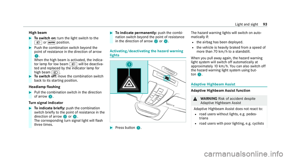
tivating/deactivating the hazard warning
lights #
Press button 1. The hazard
warning lights will switch on auto‐
matically if:
R the airbag has been deplo yed.
R theve hicle is heavily braked from a speed of
more than 70 km/h toast andstill.
When you pull away again, the hazard warning
light sy stem will switch off automatically at
appr oximately 10km/h. You can also swit choff
th e hazard warning light sy stem using but‐
to n1. Ad
aptive Highbeam Assist Ad
aptive Highbeam Assist function &
WARNING Risk of accident despite
Ad aptive Highbeam Assist
Ad aptive Highbeam Assist does not react to:
R road users without lights, e.g. pedes‐
trians
R road users with poor lighting, e.g. cyclists Light and sight
93
Page 98 of 441
#
Switch on the high beam using the combina‐
tion switch.
When the high beam is switched on automat‐
ically in the dar k,the_ indicator lamp on
th e multifunction display will light up. #
Toswitch off: switch offthe high beam
using the combination switch. Setting
theex terior lighting switch-off delay
time Multimedia sy
stem:
4 Vehicle 5
÷ Light settings
5 Exterior light shut-off #
Set the switch-off delay time. Setting
the sur round lighting Multimedia sy
stem:
4 Vehicle 5
÷ Light settings
5 Locator lighting #
Activate Oor deacti vate ª the function. If
th e sur round lighting is swit ched on, theex te‐
ri or lighting remains lit for 40 seconds af terthe
ve hicle is unloc ked. When youstart theve hicle,
th e sur round lighting is deactivated and the
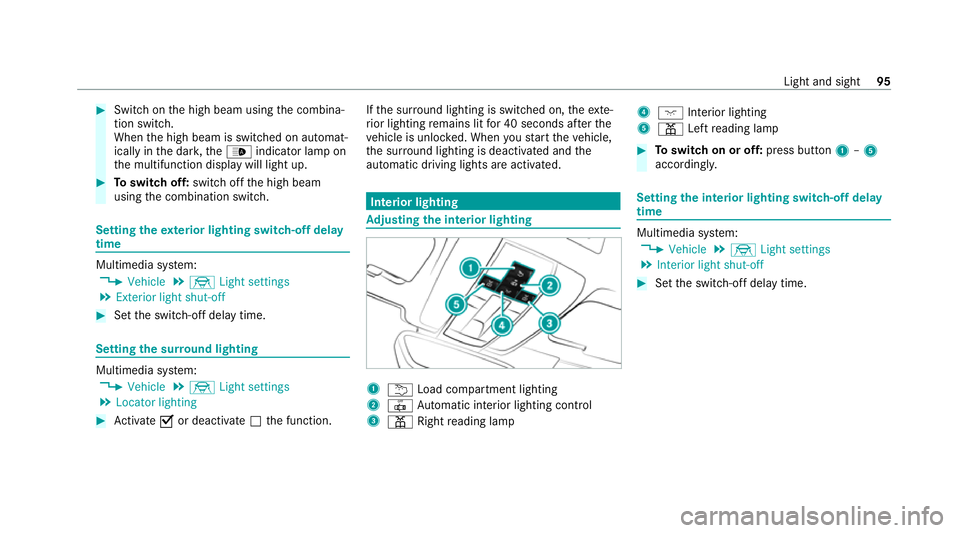
automatic driving lights are activated. Interior lighting
Ad
justing the in terior lighting 1
u Load compartment lighting
2 | Automatic interior lighting control
3 p Rightreading lamp 4
c Inte rior lighting
5 p Leftreading lamp #
Toswitch on or off: press button1–5
accordingly. Setting
the interior lighting switch-off delay
time Multimedia sy
stem:
4 Vehicle 5
÷ Light settings
5 Interior light shut-off #
Set the switch-off delay time. Light and sight
95
Page 130 of 441
th
ese exhaust gases is hazardous tohealth
and leads topoisoning. #
Never lea vethe engine or, if present,
th e auxiliary heating running in an
enclosed space wi thout suf ficient venti‐
lation. &
WARNING Risk of injury when opening
or closing a door with thega rage door
opener
When you operate or program the door with
th e integrated garage door opener, persons
in thera nge of mo vement of the door may
become trapped or be stru ck bythe door. #
Alw ays make sure that nobody is within
th era nge of mo vement of the door. Re
quirements:
R The vehicle has been par ked outside the
ga rage and outside thera nge of mo vement
of the door.
R The engine is switched off.
R The ignition is switched on. %
The garage door opener function is alw ays
av ailable when the ignition is switched on. #
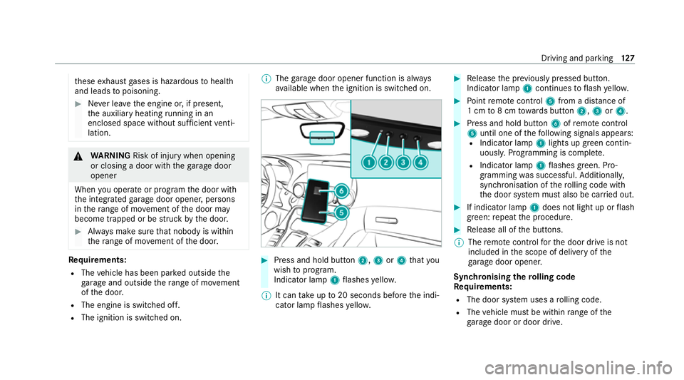
Press and hold button 2,3or4 that you
wish toprog ram.
Indicator lamp 1flashes yello w.
% It can take up to20 seconds before the indi‐
cator lamp flashes yello w. #
Release the pr eviously pressed button.
Indicator lamp 1continues toflash yello w. #
Point remo tecontrol 5from a dist ance of
1 cm to8 cm towa rds button 2,3or4. #
Press and hold button 6ofremo tecontrol
5 until one of thefo llowing signals appears:
R Indicator lamp 1lights up green contin‐
uousl y.Programming is comple te.
R Indicator lamp 1flashes green. Pro‐
gramming was successful. Additionall y,
synchronisation of thero lling code with
th e door sy stem must also be car ried out. #
If indicator lamp 1does not light up or flash
green: repeat the procedure. #
Release all of the buttons.
% The remo tecontrol forth e door drive is not
included in the scope of delivery of the
ga rage door opener.
Synchronising thero lling code
Re quirements:
R The door sy stem uses a rolling code.
R The vehicle must be within range of the
ga rage door or door drive. Driving and parking
127
Page 131 of 441
R
The vehicle as well as persons and objects
are located outside thera nge of mo vement
of the door. #
Press the programming button on the door
drive unit.
Initiate the next step within appr oximately
30 seconds. #
Press pr eviously prog rammed button 2,3
or 4 repeatedly until the door closes.
When the door closes, programming is com‐
ple ted.
% Please also read the operating instructions
fo rth e door drive.
Tr oubleshooting when prog ramming the
re mo tecont rol #
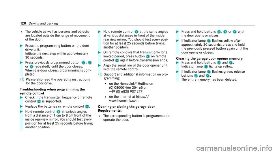
Check if the transmit ter frequency of remo te
control 5is support ed. #
Replace the batteries in remo tecontrol 5. #
Hold remo tecontrol 5atvarious angles
from a dis tance of 1 cm to8 cm front of the
inside rearview mir ror.Yo u should test eve ry
position for at least 25 seconds before trying
ano ther position. #
Hold remo tecontrol 5atthe same angles
at various dis tances in front of the inside
re arview mir ror.Yo u should test eve ryposi‐
tion for at least 25 seconds before trying
ano ther position. #
Onremo tecontrols that transmit on lyfor a
limi ted period, press button 6onremo te
control 5again before transmission ends. #
Align the aerial line of the door opener unit
with there mo tecontrol.
% Support and additional information on pro‐
gramming:
R onthe HomeLink ®
Hotline on
(0) 08000 466 354 65 or
+49 (0) 6838 907 277
R onthe Internet at https://
www.homelin k.com
Opening or closing the garage door
Re quirements:
R The cor responding button is programmed to
operate the door. #
Press and hold buttons 2,3or4 until
th e door opens or closes. #
If indicator lamp 1flashes yellow af ter
appr oximately 20 seconds: press and hold
th e pr eviously pressed button again until the
door opens or closes.
Clearing thega rage door opener memo ry #
Press and hold buttons 2and 4.
Indicator lamp 1lights up yello w. #
If indicator lamp 1flashes green: release
buttons 2and 4.
The entire memo ryhas been dele ted. 12 8
Driving and pa rking
Page 132 of 441
Electric pa
rking brake Electric parking brake function (app
lying
automatically) &
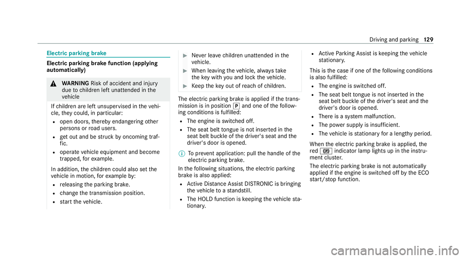
WARNING Risk of accident and inju ry
due tochildren left unat tended in the
ve hicle
If ch ildren are left unsupervised in theve hi‐
cle, they could, in part icular:
R open doors, thereby endangering other
persons or road users.
R get out and be stru ck byoncoming traf‐
fi c.
R ope rate ve hicle equipment and become
trapped, forex ample.
In addition, thech ildren could also set the
ve hicle in motion, forex ample by:
R releasing the parking brake.
R change the transmission position.
R start theve hicle. #
Never lea vechildren unat tended in the
ve hicle. #
When leaving theve hicle, alw aysta ke
th eke y with you and lock theve hicle. #
Keep theke y out of reach of children. The elect
ric pa rking brake is applied if the trans‐
mission is in position jand one of thefo llow‐
ing conditions is fulfilled:
R The engine is switched off.
R The seat belt tongue is not inser ted in the
seat belt buckle of the driver's seat and the
driver's door is opened.
% Toprev ent application: pull the handle of the
electric parking brake.
In thefo llowing situations, the electric parking
brake is also applied:
R Active Dis tance Assi stDISTRONIC is bringing
th eve hicle toast andstill.
R The HOLD function is keeping theve hicle sta‐
tionar y. R
Active Parking Assist is keeping theve hicle
st ationar y.
This is the case if one of thefo llowing conditions
is also fulfilled:
R The engine is switched off.
R The seat belt tongue is not inser ted in the
seat belt buckle of the driver's seat and the
driver's door is opened.
R There is a sy stem malfunction.
R The po wer supply is insuf ficient.
R The vehicle is stationary for a lengt hyperiod.
When the electric parking brake is applied, the
re d! indicator lamp lights up in the instru‐
ment clus ter.
The electric parking brake is not automatically
applied if the engine is switched off bythe ECO
st art/ stop function. Driving and parking
12 9
Page 133 of 441
Electric pa
rking brake function (releasing
automatically)
The elect ric pa rking brake is released when the
fo llowing conditions are fulfilled:
R The driver's door is closed.
R The engine is running.
R The transmission is in position hork and
yo u depress the accelera tor pedal or you
shift from transmission position jtoh or
k when on le velground withthe driver's
door closed.
R Ifth e transmission is in position k,theta il‐
gate must be closed.
R The seat belt tongue is inser ted into the seat
belt buckle of the driver's seat.
If th e seat belt tongue is not inser ted into the
seat belt buckle of the driver's seat, one of the
fo llowing conditions must be fulfilled:
R You shift from transmission position j.
R You ha veprev iously driven at speeds greater
th an 3 km/h. When
the electric parking brake is released, the
re d! indicator lamp in the instrument clus‐
te r goes out.
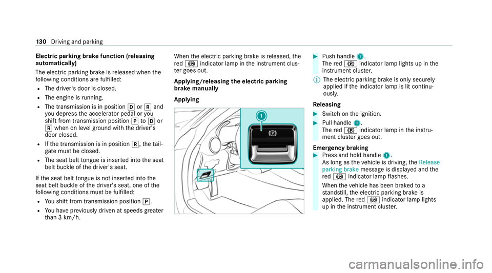
Applying/releasing the electric pa rking
brake manually
Applying #
Push handle 1.
The red! indicator lamp lights up in the
instrument clus ter.
% The electric parking brake is only securely
applied if the indicator lamp is lit continu‐
ously.
Re leasing #
Swit chon the ignition. #
Pull handle 1.
The red! indicator lamp in the instru‐
ment clus ter goes out.
Emer gency braking #
Press and hold handle 1.
As long as theve hicle is driving, theRelease
parking brake message is displa yed and the
re d! indicator lamp flashes.
When theve hicle has been braked to a
st andstill, the electric parking brake is
applied. The red! indicator lamp lights
up in the instrument clus ter. 13 0
Driving and pa rking
Page 135 of 441
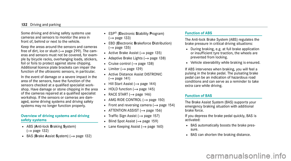
Some driving and driving safe
ty systems use
cameras and sensors tomonitor the area in
front of, behind or next totheve hicle.
Ke ep the areas around the sensors and cameras
free of dirt, ice or slush (/ page 299). The cam‐
eras and sensors must not be co vered, forex am‐
ple bybicycle rack s, overhanging loads, sticke rs,
fo il or foils toprotect against stone chipping.
Ad ditional licence plate brac kets can impair the
function of the ultrasonic sensors, in particular.
In theeve nt of damage or a severe impact in the
area of the sensors, ha vethe function of the
sensors checked at a qualified specialist work‐
shop. Ha vedamage or stone chipping in the area
of the cameras repaired at a qualified specialist
wo rkshop. If the sensors or cameras are dam‐
aged, some driving sy stems and driving saf ety
sy stems may no longer function proper ly.Overview of driving sy
stems and driving
saf ety sy stems R
ABS (Anti-lo ckBra king System)
(/ page 132)
R BAS (Bra keAssist System) (/ page132) R
ESP ®
(Electronic Stability Program)
(/ page 133)
R EBD ( Electronic Brakeforc eDistribution)
(/ page 135)
R Active Brake Assi st (/ page 135)
R Adaptive Brake Lights (/ page138)
R Cruise control (/ page 138)
R Limi ter (/ page139)
R Active Dis tance Assi stDISTRONIC
(/ page 141)
R Hill Start Assist (/ page144)
R HOLD function (/ page145)
R RACE START (/ page 146)
R AMG RIDE CONTROL (/ page150)
R Front and reve rsing camera (/ page154)
R ATTENTION ASSIST (/ page156)
R Traf fic Sign Assi st (/ page 157)
R Blind Spot Assi st (/ page 159)
R Lane Keeping Assist (/ page160) Fu
nction of ABS The Anti-lock Brake Sy
stem (ABS) regulates the
brake pressure in critical driving situations:
R During braking, e.g. at full brake application
or insuf ficient tyre traction, the wheels are
pr eve nted from lock ing.
R Vehicle steerability while braking is ensured.
If ABS inter venes when braking, you will feel a
pulsing in the brake pedal. The pulsating brake
pedal can be an indication of hazardous road
conditions and can ser veas a reminder totake
ex tra care while driving. Fu
nction of BAS The Brake Assist Sy
stem (BAS) supports your
eme rgency braking situation with additional
brake forc e.
If yo u depress the brake pedal quickl y,BA S is
acti vated:
R BAS au tomatically boosts the brake pres‐
sure.
R BAS can sho rten the braking dis tance. 13 2
Driving and pa rking
Page 137 of 441
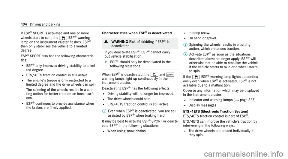
If ESP
®
SPORT is activated and one or more
wheels start tospin, the÷ ESP®
wa rning
lamp on the instrument clus terflashes. ESP ®
th en only stabilises theve hicle toa limited
deg ree.
ESP ®
SPORT also has thefo llowing characteris‐
tics:
R ESP ®
on ly impr oves driving stability toa limi‐
te d degree.
R ETS/4ETS traction control is still active.
R The engine's torque is on lyrestricted to a
limited degree and the drive wheels can spin.
The spinning of the wheels results in a cut‐
ting action for better traction on loose sur fa‐
ces.
R ESP ®
continues toprov ide assis tance when
th e brakes are firm lyapplied. Cha
racteristics when ESP ®
is deactivated &
WARNING Risk of skidding if ESP ®
is
deactivated
If yo u deactivate ESP ®
, ESP ®
cannot car ry
out vehicle stabilisation. #
ESP ®
should on lybe deactivated in the
fo llowing situations. When ESP
®
is deactivated, theå and¤
wa rning lamps light up continuously in the
instrument clus ter.
Deactivating ESP ®
has thefo llowing ef fects:
R Driving stability will no lon ger be impr oved.
R The drive wheels could spin.
R ETS/4ETS traction control is still active.
% Even when ESP ®
is deactivated, you are still
assis tedby ESP ®
when braking ha rd.
It may be best toactivate ESP ®
SPO RTor deacti‐
va te ESP ®
in thefo llowing situations:
R When using snow chains. R
In deep snow.
R On sand or gr avel.
% Spinning the wheels results in a cutting
action, which enhances traction.
% Activate ESP ®
as soon as the situations
described abo veno longer apply. ESP ®
will
ot herwise not be able tostabilise theve hicle
if th eve hicle starts toskid or a wheel starts
to spin.
If th e÷ ESP®
wa rning lamp lights up continu‐
ously even when ESP ®
is acti vated, ESP ®
is not
av ailable due toa malfunction.
Obse rve any information which may be displa yed
in the instrument clus ter:
R Indicator and warning lamps (/ page 387)
R Display messages
ETS/4ETS (Electronic Traction Sy stem)
ETS/4ETS traction control is pa rtof ESP ®
.
ETS/4ETS can impr ovetheve hicle's traction by
inter vening in thefo llowing ways:
R The drive wheels are braked individually if
they spin. 134
Driving and pa rking