2020 MASERATI GRANTURISMO CONVERTIBLE ECU
[x] Cancel search: ECUPage 223 of 296

approximately 44 lb (20 kg) being
placed on the handle of the wrench
supplied when extended for use.
•After refitting the standard wheel,
check the tire pressure.
WARNING!
•The spare wheel is narrower than
standard wheels and must only be
used to travel the distance required
to reach a service station, where the
punctured tire can be repaired or
replaced.
•Do not exceed a maximum speed of
50 mph (80 km/h) when using the
compact spare wheel; when this
limit is exceeded, the stability, road
holding and braking of the vehicle
will be compromised. Avoid
accelerating to full speed, heavy
braking and fast cornering.
•The compact spare wheel must be
inflated to the recommended tire
pressure (see “Tire Inflation
Pressure” in section “Features and
Specifications”).
•For safety reasons, it is absolutely
forbidden to drive with more than
one compact spare wheel fitted on
the vehicle.•Snow chains cannot be fitted on the
compact spare wheel.
•The spare wheel can travel a
maximum of 1,800 mi (3.000 km).
NOTE:
The used wheel may soil the mats if it
is housed in the car: insert the used
wheel in the protective bag housed in
the side pocket of the covering bag.
To Refit the Standard Wheel with
Repaired or Replaced Tire
• Following the procedure and the
caution described above, raise the
vehicle and remove the compact
spare wheel reusing the supplied
wrench with adapter, suitably
extended.
• Fit the standard wheel with repaired
or replaced tire.
• Tighten the original bolts on the
wheel.
• Lower the vehicle and remove the
jack.
• Fully tighten the bolts, alternately
tightening diametrically opposite.
WARNING!
•Observe the tightening torque for
the bolts securing the wheels (72 ±
7 lbf·ft / 98 ± 10 Nm). This is
equivalent to a load of
approximately 44 lb (20 kg) being
placed on the handle of the wrench
supplied when extended for use.
•After refitting the standard wheel,
check the tire pressure.
Once finished:
• completely deflate the compact
spare wheel by pressing on the valve
with the overhang of the valve cap;
• wrap the power cable and the
inflation hose inside the compressor
case;
• place the compressor, the jack, the
wrench and the adapter in the
In an Emergency
6
219
Page 225 of 296

Manual Release Procedure
To manually release the parking brake,
you need to use the special tool
provided in the tool kit (see "Tool Kit"
in this section).
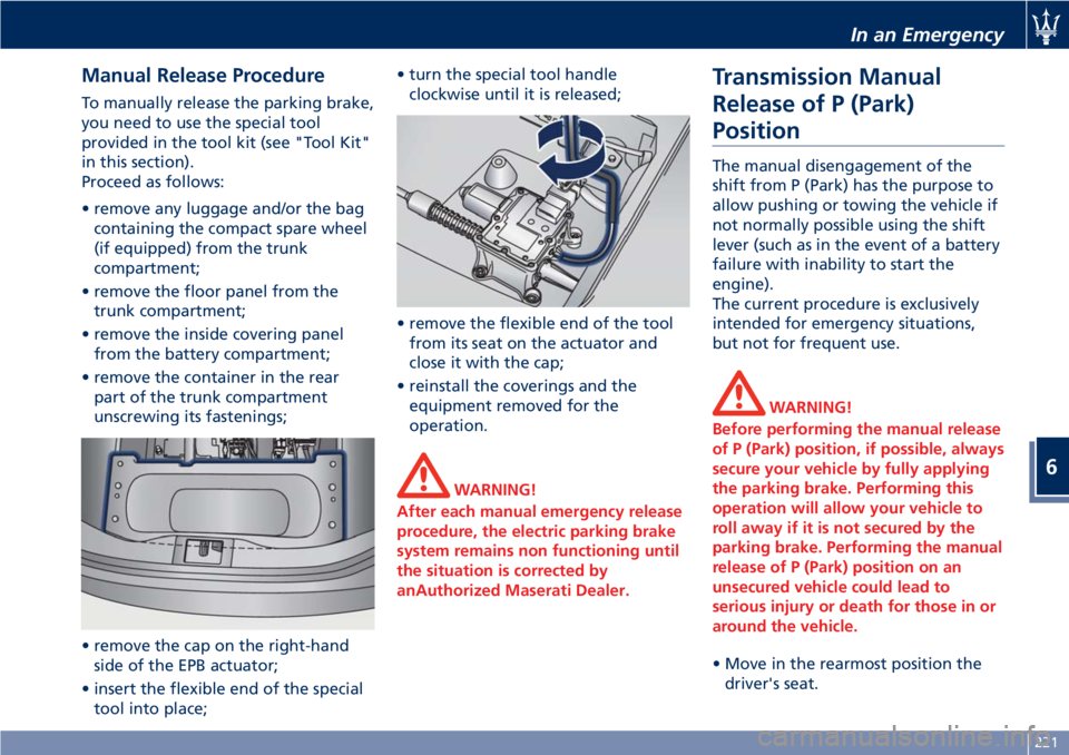
Proceed as follows:
• remove any luggage and/or the bag
containing the compact spare wheel
(if equipped) from the trunk
compartment;
• remove the floor panel from the
trunk compartment;
• remove the inside covering panel
from the battery compartment;
• remove the container in the rear
part of the trunk compartment
unscrewing its fastenings;
• remove the cap on the right-hand
side of the EPB actuator;
• insert the flexible end of the special
tool into place;• turn the special tool handle
clockwise until it is released;
• remove the flexible end of the tool
from its seat on the actuator and
close it with the cap;
• reinstall the coverings and the
equipment removed for the
operation.
WARNING!
After each manual emergency release
procedure, the electric parking brake
system remains non functioning until
the situation is corrected by
anAuthorized Maserati Dealer.
Transmission Manual
Release of P (Park)
Position
The manual disengagement of the
shift from P (Park) has the purpose to
allow pushing or towing the vehicle if
not normally possible using the shift
lever (such as in the event of a battery
failure with inability to start the
engine).
The current procedure is exclusively
intended for emergency situations,
but not for frequent use.
WARNING!
Before performing the manual release
of P (Park) position, if possible, always
secure your vehicle by fully applying
the parking brake. Performing this
operation will allow your vehicle to
roll away if it is not secured by the
parking brake. Performing the manual
release of P (Park) position on an
unsecured vehicle could lead to
serious injury or death for those in or
around the vehicle.
• Move in the rearmost position the
driver's seat.
In an Emergency
6
221
Page 230 of 296

WARNING!
•Using booster packs that have not
been checked, which could therefore
release a too high charging voltage
(higher than 14 V), in extreme
environmental conditions (for
example: closed areas or without
proper ventilation and temperatures
higher than 122°F/50°C or lower
than -4°F/-20°C) create the right
conditions for ignition which could
then cause the battery to explode.
Therefore you shall always perform
jump-starting operations using the
adequate tools and in the best
environmental conditions, taking all
necessary precautions.
•Do not attempt jump-starting if the
discharged battery is frozen. It could
rupture or explode during jump start
and cause personal injury.
•Do not carry out this procedure if
you have not done it before:
incorrect maneuvers can originate
high electrical discharges and even
cause the battery to explode.
•To avoid the risk of explosion or fire,
do not approach the battery withopen flames or cigarettes that could
generate sparks.
NOTE:
If you need to disconnect the battery
from the vehicle electrical system, see
“Maintenance - Free Battery” in
section “Maintenance and Care”).
Access the Battery
The battery is stored in the trunk.
• Open the trunk lid (see “Open and
Close the Trunk Lid” in section
“Before Starting”).
• Remove any luggage from the trunk
compartment.
• Remove the floor panel from the
trunk compartment.
• Remove the inside covering panel
from the battery compartment.Remove the cover from the right side
of the battery which protects the
positive pole.
Jump-Start Procedure
WARNING!
•The battery is secured to the vehicle
with a metal clamp (indicated in the
picture), so be extremely careful not
to let the clips on the end of the
cables come into contact with it.
•Remove any metal jewelry such as
watch bands or bracelets that might
make an inadvertent electrical
contact. You could be seriously
injured.
•Do not allow the vehicles involved in
the jump-starting operation to touch
each other as this could establish a
ground connection and cause
personal injury.
• Turn off the heater, radio, and all
unnecessary electrical accessories.
• Set the parking brake, shift the
automatic transmission into P (Park)
and turn the key in the ignition
switch toSTOP (OFF)position.
• If using another vehicle to jump start
the battery, park the vehicle within
In an Emergency
6
226
Page 232 of 296

Towing a Disabled Vehicle
Proper towing or lifting equipment is
required to prevent damage to your
vehicle. Use only towing bars and
other equipment designed for the
purpose, following equipment
manufacturer’s instructions.
Safety chains are mandatory.
Except for the front threaded seat to
fix the supplied hook (see “Tool Kit”
chapter in this section), the vehicle is
not equipped with other connection
points for towing operations with tow
truck.
CAUTION!
Any improper maneuver and use of
unsuitable equipment for recovering
vehicle in an emergency from off road
location could seriously damage the
vehicle. Contact theAuthorized
Maserati Dealeror anyone having
suitable equipment and the required
expertise to safely and properly carry
out any required operations.
Make sure you comply with local
towing regulations.
•If the vehicle's battery is discharged,
it is necessary to shift the automatic
transmission out of the P (Park)Position and release the parking
brake (see “ Transmission Manual
Release of P (Park) position” and
“Emergency Release of the Parking
Brake” in this section).
•If the vehicle battery is still charged,
turn off the engine and disengage
the parking brake manually (if
automatically engaged) by using the
command at the side of the
transmission shift lever (see “Parking
Brake” chapter in section “Driving”).
Shift then manually the transmission
out of P (Park) as described in
“Transmission Manual Release of P
(Park) Position” chapter of this
section. If you need to use the
accessories (wipers, defrosters, etc.)
while being towed, the key in the
ignition switch must be turned in
MAR (ON)position, do not use the
ACCposition.
Vehicle Towing Conditions
Maserati only allows vehicle towing
either on a flatbed or with all four
wheels off the ground.
If flatbed equipment is not available,
and the transmission is still operable,
the vehicle may be flat towed (with all
four wheels on the ground) under the
following conditions.• The shift lever must be in N (Neutral).
• The distance to be traveled must not
exceed 30 mi (50 km ).
• The towing speed must not exceed
30 mph (50 km/h).
If the transmission is not operable, or
the vehicle must be towed faster than
30 mph (50 km/h ) or farther than 30
mi (50 km) (for example on a
highway), tow with the rear driving
wheels off the ground and on a
platform of a rescue vehicle, or with
the rear wheels raised using a wheel
lift.
CAUTION!
If you have to tow the vehicle with 2
wheels raised, ensure that the key in
the ignition switch is in theSTOP (OFF)
position. If this is not observed, when
the ESC is active, the ECU will store a
malfunction and the relative indicator
light
will illuminate on the
instrument cluster display. This
requires the intervention of an
Authorized Maserati Dealerto reset
the system.
In an Emergency
6
228
Page 246 of 296

(Continued)
www.P65Warnings.ca.gov/passenger-
vehicle
Brake Fluid Level Check
Check the fluid level immediately if
the brake system
red warning
light and the related message turn on
indicating a low level of brake fluid.
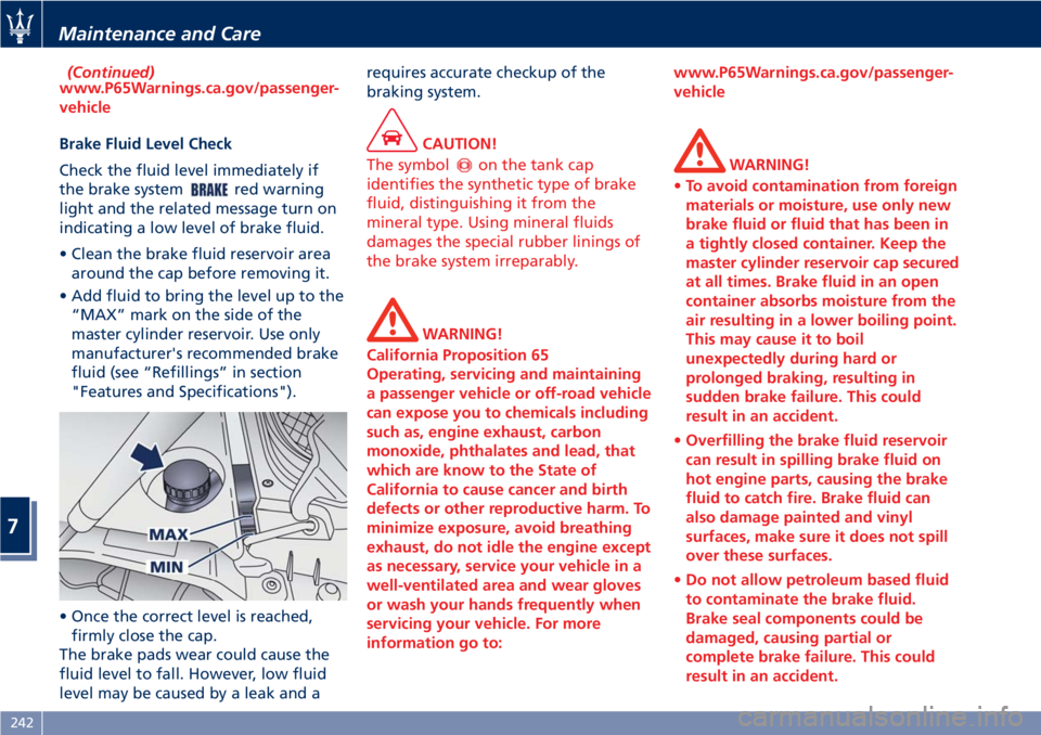
• Clean the brake fluid reservoir area
around the cap before removing it.
• Add fluid to bring the level up to the
“MAX” mark on the side of the
master cylinder reservoir. Use only
manufacturer's recommended brake
fluid (see “Refillings” in section
"Features and Specifications").
• Once the correct level is reached,
firmly close the cap.
The brake pads wear could cause the
fluid level to fall. However, low fluid
level may be caused by a leak and arequires accurate checkup of the
braking system.
CAUTION!
The symbol
on the tank cap
identifies the synthetic type of brake
fluid, distinguishing it from the
mineral type. Using mineral fluids
damages the special rubber linings of
the brake system irreparably.
WARNING!
California Proposition 65
Operating, servicing and maintaining
a passenger vehicle or off-road vehicle
can expose you to chemicals including
such as, engine exhaust, carbon
monoxide, phthalates and lead, that
which are know to the State of
California to cause cancer and birth
defects or other reproductive harm. To
minimize exposure, avoid breathing
exhaust, do not idle the engine except
as necessary, service your vehicle in a
well-ventilated area and wear gloves
or wash your hands frequently when
servicing your vehicle. For more
information go to:www.P65Warnings.ca.gov/passenger-
vehicle
WARNING!
•To avoid contamination from foreign
materials or moisture, use only new
brake fluid or fluid that has been in
a tightly closed container. Keep the
master cylinder reservoir cap secured
at all times. Brake fluid in an open
container absorbs moisture from the
air resulting in a lower boiling point.
This may cause it to boil
unexpectedly during hard or
prolonged braking, resulting in
sudden brake failure. This could
result in an accident.
•Overfilling the brake fluid reservoir
can result in spilling brake fluid on
hot engine parts, causing the brake
fluid to catch fire. Brake fluid can
also damage painted and vinyl
surfaces, make sure it does not spill
over these surfaces.
•Do not allow petroleum based fluid
to contaminate the brake fluid.
Brake seal components could be
damaged, causing partial or
complete brake failure. This could
result in an accident.
Maintenance and Care
7
242
Page 255 of 296

Fuse Replacement
Used Fuses Characteristics
When an electrical device is not
functioning, check that the
corresponding fuse is in proper
working order (intact).
AFuse intact
BFuse blown
Replace the faulty fuse with a new
one featuring the same rating, by
using appropriate forceps.The color identifies the value of the
fuses in amperes which is also
reported on them.
The vehicle is endowed with mini- and
maxi-fuses.
The table shows the match between
color and amperage of mini and maxi
fuses.
Type
Mini Fuse Maxi Fuse
Beige - 5 Yellow - 20
Brown - 7.5 Green - 30
Red - 10 Orange - 40
Blue-15 Red-50
Yellow - 20 Blue - 60
White - 25
Green - 30
CAUTION!
• Never replace a blown fuse with
anything other than a new and
suitable fuse (same rating).
• After replacing a fuse, if the fault
recurs, contact anAuthorized
Maserati Dealer.
Position of Fuses
The fuses are located in three parts of
the vehicle, namely:
• On the right hand side of the engine
compartment.
• Behind the glove compartment, to
the left of the steering wheel.
• In the trunk compartment next to
the battery.
Fuses Inside Engine
Compartment
• To access the fuses, lift the hood and
remove the covering panel.
Maintenance and Care
7
251
Page 256 of 296

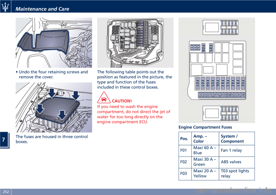
• Undo the four retaining screws and
remove the cover.
The fuses are housed in three control
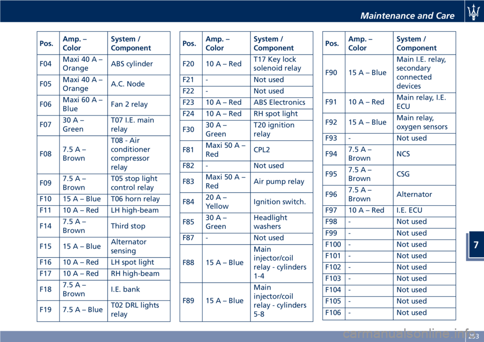
boxes.The following table points out the
position as featured in the picture, the
type and function of the fuses
included in these control boxes.
CAUTION!
If you need to wash the engine
compartment, do not direct the jet of
water for too long directly on the
engine compartment ECU.
Engine Compartment Fuses
Pos.Amp. –
ColorSystem /
Component
F01Maxi 60 A –
BlueFan 1 relay
F02Maxi 30 A –
GreenABS valves
F03Maxi 20 A –
YellowT03 spot lights
relay
Maintenance and Care
7
252
Page 257 of 296

Pos.Amp. –
ColorSystem /
Component
F04Maxi 40 A –
OrangeABS cylinder
F05Maxi 40 A –
OrangeA.C. Node
F06Maxi 60 A –
BlueFan 2 relay
F0730A–
GreenT07 I.E. main
relay
F087.5A–
BrownT08 - Air
conditioner
compressor
relay
F097.5A–
BrownT05 stop light
control relay
F10 15 A – Blue T06 horn relay
F11 10 A – Red LH high-beam
F147.5A–
BrownThird stop
F15 15 A – BlueAlternator
sensing
F16 10 A – Red LH spot light
F17 10 A – Red RH high-beam
F187.5A–
BrownI.E. bank
F19 7.5 A – BlueT02 DRL lights
relayPos.Amp. –
ColorSystem /
Component
F20 10 A – RedT17 Key lock
solenoid relay
F21 - Not used
F22 - Not used
F23 10 A – Red ABS Electronics
F24 10 A – Red RH spot light
F3030A–
GreenT20 ignition
relay
F81Maxi 50 A –
RedCPL2
F82 - Not used
F83Maxi 50 A –
RedAir pump relay
F8420A–
YellowIgnition switch.
F8530A–
GreenHeadlight
washers
F87 - Not used
F88 15 A – BlueMain
injector/coil
relay - cylinders
1-4
F89 15 A – BlueMain
injector/coil
relay - cylinders
5-8Pos.Amp. –
ColorSystem /
Component
F90 15 A – BlueMain I.E. relay,
secondary
connected
devices
F91 10 A – RedMain relay, I.E.
ECU
F92 15 A – BlueMain relay,
oxygen sensors
F93 - Not used
F947.5A–
BrownNCS
F957.5A–
BrownCSG
F967.5A–
BrownAlternator
F97 10 A – Red I.E. ECU
F98 - Not used
F99 - Not used
F100 - Not used
F101 - Not used
F102 - Not used
F103 - Not used
F104 - Not used
F105 - Not used
F106 - Not used
Maintenance and Care
7
253