2020 MASERATI GRANTURISMO CONVERTIBLE ECU
[x] Cancel search: ECUPage 66 of 296

the distance (maximum/average/
minimum) and the position
(front/rear/central/side) of the obstacle
detected.
The color represents the distance,
while the field represents the position.
The green color represents the
maximum distance detected, the
yellow color the medium distance and
the red color the minimum one. The
rear sensors are not shown in the
image on the instrument cluster
display if only the front sensors are
active.
WARNING!
For the system to operate correctly the
sensors positioned on the bumper
must be kept clean (remove any mud,
dirt, snow or ice).
Sensor Range
The sensors allow the system to
monitor the front and rear of the
vehicle; they are positioned so as to
monitor the central and lateral zones
at the front and at the rear of the
vehicle.
In the event of an obstacle located in a
central area, this will be detected at
distances of less than 35 in (0,9 m) at
the front and 59 in (1,50 m) at the rear,
depending on the type of obstacle and
its dimensions.
If the obstacle is located in a lateral
position, it will be detected at
distances of less than 31 in (0,8 m).
Failure Indicators
The system ECU checks all the
components every time R (Reverse)
gear is engaged.
In the event that the parking sensors
fail, the relative
warning light and
message illuminate on the instrument
cluster display.
In the event of a failure signal, stop
the vehicle and turn the key in the
ignition switch toSTOP (OFF)position.
Then try cleaning the sensors or
moving the vehicle away from any
possible ultrasound sources (e.g.
pneumatic truck brakes or pneumatichammers) and rotate the key to the
MAR (ON)position. So, if the
operating failure cause has been
eliminated, system full operation will
be recovered. If however, the failure
beep continues, contact anAuthorized
Maserati Dealerto have the system
checked.
Cleaning the Park Assist
Sensors
When cleaning the sensors, take
special care not to scratch or damage
them; therefore, do not use dry, rough
or hard cloths.
The sensors must be washed with clean
water, possibly adding car shampoo.
Should you need to repaint the
bumper or in case of paint touch-ups
in the sensor area, please contact
exclusively theAuthorized Maserati
Dealer. Incorrect paint application
could affect the parking sensors
operation.
Park Assist System Usage
Precautions
NOTE:
•Jackhammers, large trucks, and other
vibrations could affect the
performance of Park Assist.
Before Starting
2
62
Page 70 of 296
Vehicle Safety Checks
Seat Belts
• Inspect the belt system periodically,
checking for cuts, frays, and loose
parts. Damaged parts must be
replaced immediately.
• Do not disassemble or modify the
system.
• If the belt has been sharply pulled,
for example as the result of an
accident, the safety belt, together
with the anchoring devices, the
anchoring device mounting screws
and the pretensioner must be
completely replaced. Even if the belt
does not present any exterior signs
of wear or damage, it may have lost
its restraining properties.
Air bag Warning Light
The
warning light should illuminate
and remain lit for a few seconds bulb
checking when the key in the ignition
switch is turned inMAR (ON)position
(see “Supplemental Restraint System
(SRS) — Air bags” chapter in this
section).
•Ifthe
warning light does not
illuminate while starting, contact an
Authorized Maserati Dealer.•Ifthe
warning light stays on,
flickers, or comes on while driving,
have the system checked by an
Authorized Maserati Dealer.
Defroster
Check operation by selecting the
defrost mode and place the fan system
on high speed (see “Air Conditioning
Controls” chapter in section
“Dashboard Instruments and
Controls”).
You should be able to feel the air
directed against the windshield and
front side windows. Contact an
Authorized Maserati Dealerfor service
if your defroster is inoperable.
Floor Mat
Always use floor mats designed to fit
the footwell of your vehicle. Use only
floor mats that leave the pedal area
unobstructed and that are firmly
secured so that they cannot slip out of
position and interfere with the pedals
or impair safe operation of your
vehicle.
NOTE:
TheAuthorized Maserati Dealercan
provide you with any information
about the available Maserati floor
mats included in the “Genuine
Accessories” range.
WARNING!
Pedals that cannot move freely can
cause loss of vehicle control and
increase the risk of serious personal
injury.
•Always make sure that floor mats
are properly attached to the proper
fasteners.
•Never place or install floor mats or
other floor coverings in the vehicle
that cannot be properly secured to
prevent them from moving and
interfering with the pedals.
•Never put floor mats or other floor
coverings on top of already installed
floor mats. Additional floor mats and
other coverings will reduce the size
of the pedal area and interfere with
the pedals.
•Check mounting of mats on a regular
basis. Always properly reinstall and
secure floor mats that have been
removed for cleaning.
•Always make sure that objects
cannot fall into the driver footwell
while the vehicle is moving. Objects
can become trapped under the brake
pedal and accelerator pedal causing
a loss of vehicle control.
Before Starting
2
66
Page 78 of 296
Front Seats
Seats and seat belts are part of the
Occupant Restraint System of the
vehicle. For further information, see
chapter “Occupant Restraint System”
in Section “Before Starting”.
WARNING!
Be sure everyone in your vehicle is in a
seat and using a seat belt properly.
Seat Adjustments
The seats can only be adjusted with
the key in the ignition switch inMAR
(ON)position.
It is however possible, when the door
is closed, to operate the seat for
approx. 15 seconds after turning the
key toSTOP (OFF)position and then
for other 15 seconds after the last
operation.
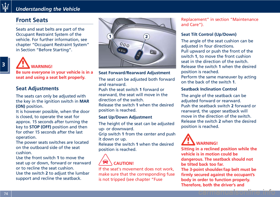
The power seats switches are located
on the outboard side of the seat
cushion.
Use the front switch1to move the
seat up or down, forward or rearward
or to recline the seat cushion.
Use the switch2to adjust the lumbar
support and recline the seatback.Seat Forward/Rearward Adjustment
The seat can be adjusted both forward
and rearward.
Push the seat switch1forward or
rearward, the seat will move in the
direction of the switch.
Release the switch1when the desired
position is reached.
Seat Up/Down Adjustment
The height of the seat can be adjusted
up- or downward.
Grip switch1from the center and push
it down or up.
Release the switch1when the desired
position is reached.
CAUTION!
If the seat's movement does not work,
make sure that the corresponding fuse
is not tripped (see chapter “FuseReplacement” in section “Maintenance
and Care”).
Seat Tilt Control (Up/Down)
The angle of the seat cushion can be
adjusted in four directions.
Pull upward or push the front of the
switch1, to move the front cushion
seat in the direction of the switch.
Release the switch1when the desired
position is reached.
Perform the same maneuver by acting
on the back of the switch1.
Seatback Inclination Control
The angle of the seatback can be
adjusted forward or rearward.
Push the seatback switch2forward or
rearward, the upper seatback will
move in the direction of the switch.
Release the switch2when the desired
position is reached.
WARNING!
Sitting in a reclined position while the
vehicle is in motion could be
dangerous. The seatback should not
be tilted back too far.
The 3-point shoulder/lap belt must be
firmly secured against the occupant’s
body in order to function properly.
Therefore, both the driver’s and
Understanding the Vehicle
3
74
Page 104 of 296

• Turn the wrench clockwise to move
the soft top edge closer to the
windshield, and fasten the fastening
latches inside the locks.
• Remove the unlocking/locking
wrench from the soft top seat and
place it in the tool kit box together
with the screwdriver.Windstop (optional)
The Windstop consists of a panel fitted
behind the front seats, which prevents
the wind from creating turbulence in
the passenger compartment when the
soft top is open. The Windstop can
also be left installed with soft top
closed.
WARNING!
With Windstop installed you can not
carry passengers in the rear seats.
The Windstop is normally stored in a
protective bag inside the trunk
compartment.
This bag is secured inside the
compartment by means of a strap.
CAUTION!
• It is recommended not to place sharp
and pointed objects which may
contact the protective bag in the
trunk compartment, unless they are
firmly secured.
• You should not place objects on the
Windstop protective bag, even if
they are secured, as they maydamage the Windstop with their
weight.
NOTE:
If the vehicle is equipped with spare
wheel (optional), it may not house in
the trunk compartment the Windstop
inside its bag.
Fitting the Windstop
• Take the Windstop out of its bag.
• Turn the lower left-hand part, until it
is fully laid out.
• Join the rear section to the base of
the Windstop.
Understanding the Vehicle
3
100
Page 111 of 296
Cargo Area
WARNING!
To help protect against personal
injury, passengers must not be seated
in the rear cargo area. The rear cargo
space is intended for load carrying
purposes only, not for passengers,
who should sit in seats and use seat
belts.
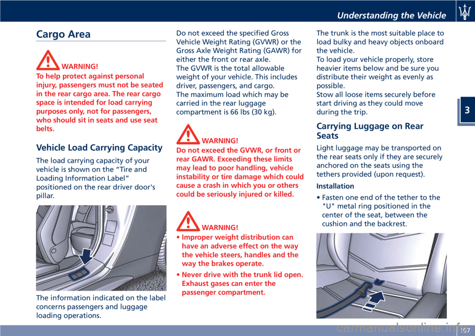
Vehicle Load Carrying Capacity
The load carrying capacity of your
vehicle is shown on the “Tire and
Loading Information Label”
positioned on the rear driver door's
pillar.
The information indicated on the label
concerns passengers and luggage
loading operations.Do not exceed the specified Gross
Vehicle Weight Rating (GVWR) or the
Gross Axle Weight Rating (GAWR) for
either the front or rear axle.
The GVWR is the total allowable
weight of your vehicle. This includes
driver, passengers, and cargo.
The maximum load which may be
carried in the rear luggage
compartment is 66 lbs (30 kg).
WARNING!
Do not exceed the GVWR, or front or
rear GAWR. Exceeding these limits
may lead to poor handling, vehicle
instability or tire damage which could
cause a crash in which you or others
could be seriously injured or killed.
WARNING!
•Improper weight distribution can
have an adverse effect on the way
the vehicle steers, handles and the
way the brakes operate.
•Never drive with the trunk lid open.
Exhaust gases can enter the
passenger compartment.
The trunk is the most suitable place to
load bulky and heavy objects onboard
the vehicle.
To load your vehicle properly, store
heavier items below and be sure you
distribute their weight as evenly as
possible.
Stow all loose items securely before
start driving as they could move
during the trip.
Carrying Luggage on Rear
Seats
Light luggage may be transported on
the rear seats only if they are securely
anchored on the seats using the
tethers provided (upon request).
Installation
• Fasten one end of the tether to the
"U" metal ring positioned in the
center of the seat, between the
cushion and the backrest.
Understanding the Vehicle
3
107
Page 112 of 296
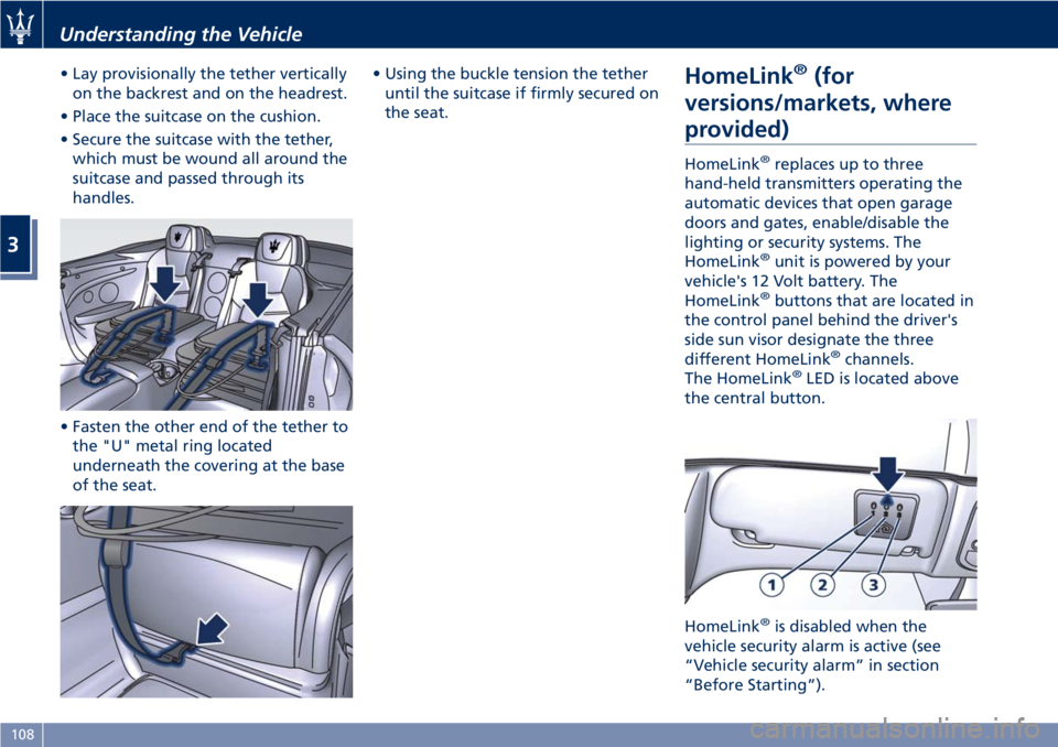
• Lay provisionally the tether vertically
on the backrest and on the headrest.
• Place the suitcase on the cushion.
• Secure the suitcase with the tether,
which must be wound all around the
suitcase and passed through its
handles.
• Fasten the other end of the tether to
the "U" metal ring located
underneath the covering at the base
of the seat.• Using the buckle tension the tether
until the suitcase if firmly secured on
the seat.HomeLink®(for
versions/markets, where
provided)
HomeLink®replaces up to three
hand-held transmitters operating the
automatic devices that open garage
doors and gates, enable/disable the
lighting or security systems. The
HomeLink
®unit is powered by your
vehicle's 12 Volt battery. The
HomeLink
®buttons that are located in
the control panel behind the driver's
side sun visor designate the three
different HomeLink
®channels.
The HomeLink®LED is located above
the central button.
HomeLink
®is disabled when the
vehicle security alarm is active (see
“Vehicle security alarm” in section
“Before Starting”).
Understanding the Vehicle
3
108
Page 118 of 296

Sport Skyhook Suspension
(for versions/markets,
where provided)
The electronic system controlling the
vehicle suspension uses the
sophisticated on board sensors and is
aimed at optimizing vehicle
performance.
The system is capable of constantly
monitoring suspension damping by
means of the actuator fitted on each
shock absorber (Skyhook type). This
way, the shock absorber setting is
suited to the road surface conditions
and vehicle dynamics, thus improving
passenger comfort and road-holding.
By pressing button “SPORT” on the
central console the driver can choose,
even while driving, a normal or
dynamic-type setting for the
suspension, depending on their own
driving style.This way, the system operates with a
shock absorber “softer” setting in
NORMAL drive mode, and a “harder”
setting if SPORT drive mode is selected
(see “Drive Mode” in section
“Driving”).
The strategy used by the system
controlling suspension damping is
aimed at reducing the vertical
oscillations of the vehicle (rolling and
pitching) to a minimum.
The activation of SPORT drive mode
sets the suspension for sports-style
driving and acts on the ASR and
gearbox systems as well, modifying
their setting for dynamic-style driving.
System Components
The system is controlled by an ECU
which manages the solenoid valves on
each shock absorber in response to the
sensor signals, thus adjusting
suspension damping and setting.The sensors which enable the ECU to
calculate the vehicle speed, vertical
and side acceleration, as well as the
instantaneous braking system pressure,
thereby controlling suspension
damping, are the following:
• front left-hand vertical acceleration
sensor;
• front right-hand vertical acceleration
sensor;
• rear vertical acceleration sensor;
• front left-hand wheel acceleration
sensor;
• front right-hand wheel acceleration
sensor;
• lateral acceleration sensor;
• driving speed sensor;
• brake pedal switch.
Self-diagnostics
Whenever the engine is started, the
system performs a self-diagnostic cycle.
If a malfunction is found, the
amber
warning light is displayed
accompanied by the message “Check
suspensions” (see paragraph
"Malfunction Indicators" in this
chapter).
Understanding the Vehicle
3
114
Page 119 of 296
Calibration Selection
The driver can select, in relation to
road surface conditions, vehicle speed,
driving style and comfort, one of the
two calibration levels provided by the
system: normal or sports-style.
•Normal calibration, active when
SPORT drive mode is disabled
("SPORT" button not pressed), favors
comfort and higher driving stability
with low and average grip
conditions.
•Sport-style calibration, active when
SPORT drive mode is enabled
("SPORT" button pressed) , favors
wheel drive and permits a
dynamic-style driving with optimal
road holding.
Whenever the engine is started, the
system automatically activates
NORMAL drive mode, even if SPORT
drive mode was selected before the
engine was last turned off.
The sport-style calibration can be
selected only with the key in the
ignition switch inMAR (ON)position
and it is enabled by pressing button
"SPORT", even while driving.
When SPORT drive mode is activated,
the word “SPORT” on the instrument
cluster display and the LED on the
button illuminate.WARNING!
SPORT drive mode should not be
activated if the road surface is rough
or slippery.
The electronic suspension control
system works in combination with the
ESC system.
When the suspension is set to normal
calibration, stability is increased under
medium and low grip conditions,
while when it is set to sport-style
calibration, the ESC system optimizes a
sportier driving.
WARNING!
In low- and medium-grip conditions
(e.g., rain, snow, ice, sand, etc.) it is
advisable not to use SPORT drive
mode, even with the ESC system
enabled.
Malfunction Indicators
If one or more electric components in
the system prove to be malfunctioning
while driving, the ECU illuminates the
amber warning light accompanied
by the message “Check suspensions”
on the display. In addition, the ECU
calibrates the shock absorbers to apreset value, thus ensuring a safe
vehicle set up.
Should the malfunction involve one
shock absorber only, this will no
longer be controlled by the ECU and
will therefore remain set as it was
when the fault occurred. It is
therefore possible for one of the four
shock absorbers to work with a fixed
calibration, different from that of the
other ones.
In any case, safe and secure vehicle
driving is always ensured at low
speeds.
CAUTION!
In the event of a malfunction in the
suspension control electronic system,
which will be indicated by the
illumination of the amber warning
light on the display while driving,
keep a moderate speed and have the
vehicle checked as soon as possible by
anAuthorized Maserati Dealer.
If a malfunction occurs while driving,
and this is signaled by the illumination
of the
amber warning light on the
display, it is advisable to stop the
vehicle as soon as possible, turn the
key in the ignition switch toSTOP
(OFF)position and then restart the
engine.
Understanding the Vehicle
3
115