2020 MASERATI GRANTURISMO CONVERTIBLE key
[x] Cancel search: keyPage 95 of 296
Windshield Washers and
Headlight Washers
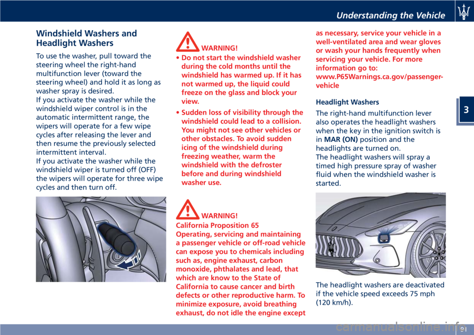
To use the washer, pull toward the
steering wheel the right-hand
multifunction lever (toward the
steering wheel) and hold it as long as
washer spray is desired.
If you activate the washer while the
windshield wiper control is in the
automatic intermittent range, the
wipers will operate for a few wipe
cycles after releasing the lever and
then resume the previously selected
intermittent interval.
If you activate the washer while the
windshield wiper is turned off (OFF)
the wipers will operate for three wipe
cycles and then turn off.WARNING!
•Do not start the windshield washer
during the cold months until the
windshield has warmed up. If it has
not warmed up, the liquid could
freeze on the glass and block your
view.
•Sudden loss of visibility through the
windshield could lead to a collision.
You might not see other vehicles or
other obstacles. To avoid sudden
icing of the windshield during
freezing weather, warm the
windshield with the defroster
before and during windshield
washer use.
WARNING!
California Proposition 65
Operating, servicing and maintaining
a passenger vehicle or off-road vehicle
can expose you to chemicals including
such as, engine exhaust, carbon
monoxide, phthalates and lead, that
which are know to the State of
California to cause cancer and birth
defects or other reproductive harm. To
minimize exposure, avoid breathing
exhaust, do not idle the engine exceptas necessary, service your vehicle in a
well-ventilated area and wear gloves
or wash your hands frequently when
servicing your vehicle. For more
information go to:
www.P65Warnings.ca.gov/passenger-
vehicle
Headlight Washers
The right-hand multifunction lever
also operates the headlight washers
when the key in the ignition switch is
inMAR (ON)position and the
headlights are turned on.
The headlight washers will spray a
timed high pressure spray of washer
fluid when the windshield washer is
started.
The headlight washers are deactivated
if the vehicle speed exceeds 75 mph
(120 km/h).
Understanding the Vehicle
3
91
Page 97 of 296

this problem let more air into the
passenger compartment.
• It is advisable to close the soft top
when parking the vehicle. This not
only protects the passenger
compartment against weather
agents, but is also a safeguard
against theft.
• If possible, park in the shade as
prolonged exposure to the sun will
alter the canvas fiber and color.
• Before disconnecting the battery,
lower the side windows by about 1.6
- 2 in (4 - 5 cm) to prevent damaging
the soft top strip when the doors are
opened and closed. When the
battery is connected and fully
charged, this operation is performed
automatically whenever the doors
are opened or closed. The windows
must remain lowered until the
recharged battery is reconnected. If
the battery is dead and the windows
are fully up, only open the doors
when strictly necessary and being
extremely careful: do not close them
again until the windows can be
lowered.
• Cover the soft top with a protective
cloth when it is going to be parked
outdoor for a long period of time.• To avoid damaging the soft top, the
vehicle must not be washed with
high-pressure water jet systems, be it
a manual nozzle or an automatic car
wash with turning rollers.
• Organic residues must be
immediately removed, as they may
damage both the soft top fabric and
its strips.
• Do not use solvents, alcohol, petrol
or other generic detergents to clean
the soft top.
"Summer open" Strategy
Using the key inserted in the external
driver's door lock, you can control the
soft top opening/closing strategy
referred to as “Summer open”.
NOTE:
•The opening and closing cycle can be
interrupted at any time, moving the
key back to its initial position.
•The following operations are
performed with the engine off. This
involves an extremely high power
consumption, which causes the
battery to discharge faster.
With the soft topfully closed:
• insert the key in the external driver’s
door lock;• turn the key clockwise until
unlocking the doors and hold it in
this position. The automatic soft top
opening cycle will begin after
approx. 2 seconds;
• do not move the key for the entire
opening cycle.
With the soft topfully open:
• insert the key in the external driver’s
door lock;
• turn the key counterclockwise until
locking the doors and hold it in this
position. The automatic soft top
closing cycle will begin after approx.
2 seconds;
• do not move the key for the entire
closing cycle.
Understanding the Vehicle
3
93
Page 98 of 296
Soft Top Operation
The soft top must be opened and
closed with the vehicle stationary and,
as a rule, with the engine running at
idle speed.
If necessary (e.g. in closed places) the
operation can be performed with the
engine off and the key in the ignition
switch inMAR (ON)position. This
operation involves an extremely high
power consumption, which causes the
battery to discharge faster.
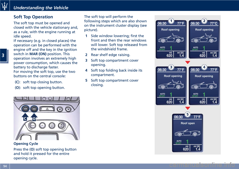
For moving the soft top, use the two
buttons on the central console:
(C): soft top closing button.
(O): soft top opening button.
Opening Cycle
Press the (O) soft top opening button
and hold it pressed for the entire
opening cycle.The soft top will perform the
following steps which are also shown
on the instrument cluster display (see
picture).
1Side window lowering; first the
front and then the rear windows
will lower. Soft top released from
the windshield frame.
2Rear shelf edge raising.
3Soft top compartment cover
opening.
4Soft top folding back inside its
compartment.
5Soft top compartment cover
closing.
Understanding the Vehicle
3
94
Page 102 of 296

NOTE:
The soft top failure temporarily
disables, for approx. 10 minutes, the
power windows’ operation. After this
time, the power windows will resume
normal functioning.
Soft Top Manual Closing
Operation
In case of need, the soft top may be
closed manually.
WARNING!
•Manual operation of the soft top for
emergency closing requires the
presence of two persons in order to
prevent personal injury or damage
to the car.
•When moving the soft top by hand,
take the greatest care as its movable
parts could squeeze or trap objects
or parts of your body.
CAUTION!
The emergency procedure described
below must be used to close the soft
top if it is not possible for you to
contact theAuthorized Maserati
Dealerimmediately and you cannot
keep the soft top open.
If the failure occurs when the opening
procedure is already in progress, do
not attempt to complete the
procedure - close back the soft top
manually according to the following
instructions. After depressurizing the
hydraulic circuit by turning the key in
the ignition switch toSTOP (OFF)
position, perform the emergency
procedure starting from the point at
which the opening stage jammed.
WARNING!
After depressurizing the system, the
soft top will move freely. Therefore, if
it is not in a balanced position, it will
close or open as a consequence of its
weight. Take the greatest care to
avoid being squeezed or trapped by
its levers and mechanisms.
Before Starting
NOTE:
•During emergency closing, the side
windows must be lowered.
•
To move the soft top manually, you
must depressurize the hydraulic system
by turning the key in the ignition
switch to
STOP (OFF)position and
waiting approx. 10 minutes.•To avoid unintentional activations,
we recommend that you remove the
key from the ignition switch. Take
the flat-head screwdriver and the
wrench to lock/unlock the soft top
hinges out of the tool kit located in
the trunk compartment (see "Tool
Kit" in section "In an Emergency").
Soft Top Closing
• Using a flat head screwdriver, remove
the access covers (housed on both
sides of the compartment) turning
the relative fastening screws
counterclockwise by a quarter of a
turn.
• Reach the small cables through the
slots and pull them to unlock the soft
top cover locks.
• Reassemble the access covers and
lock them turning the following
screw clockwise.
Understanding the Vehicle
3
98
Page 106 of 296
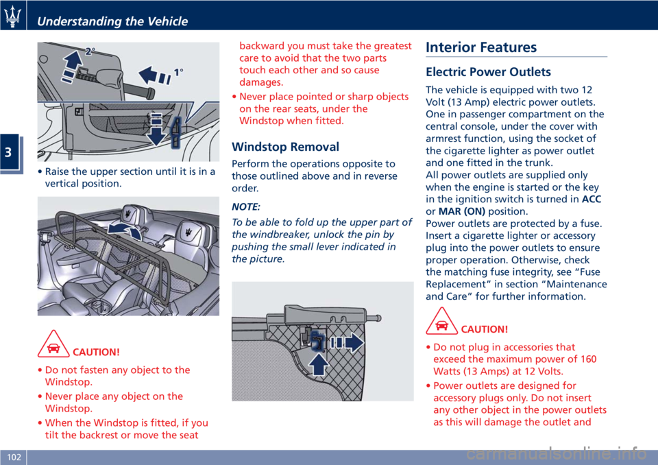
• Raise the upper section until it is in a
vertical position.
CAUTION!
• Do not fasten any object to the
Windstop.
• Never place any object on the
Windstop.
• When the Windstop is fitted, if you
tilt the backrest or move the seatbackward you must take the greatest
care to avoid that the two parts
touch each other and so cause
damages.
• Never place pointed or sharp objects
on the rear seats, under the
Windstop when fitted.
Windstop Removal
Perform the operations opposite to
those outlined above and in reverse
order.
NOTE:
To be able to fold up the upper part of
the windbreaker, unlock the pin by
pushing the small lever indicated in
the picture.
Interior Features
Electric Power Outlets
The vehicle is equipped with two 12
Volt (13 Amp) electric power outlets.
One in passenger compartment on the
central console, under the cover with
armrest function, using the socket of
the cigarette lighter as power outlet
and one fitted in the trunk.
All power outlets are supplied only
when the engine is started or the key
in the ignition switch is turned inACC
orMAR (ON)position.
Power outlets are protected by a fuse.
Insert a cigarette lighter or accessory
plug into the power outlets to ensure
proper operation. Otherwise, check
the matching fuse integrity, see “Fuse
Replacement” in section “Maintenance
and Care” for further information.
CAUTION!
• Do not plug in accessories that
exceed the maximum power of 160
Watts (13 Amps) at 12 Volts.
• Power outlets are designed for
accessory plugs only. Do not insert
any other object in the power outlets
as this will damage the outlet and
Understanding the Vehicle
3
102
Page 108 of 296

Cupholders for Rear Passengers
The rear cupholders are available on
the rear part of the central console,
between the rear seats.
Multimedia Ports and Phone
Housing Compartment
Multimedia ports and the housing for
the phone are located in a
compartment inside the central
console. To access this compartmentlift the cover with armrest function as
previously described.
If the front passenger wants to use the
phone connected to the USB port, you
can route the cable to the right-hand
side of the hooking area of the cover
opening handle shown in picture.
To avoid the risk of being pinched
when closing the cover, the cable
diameter that properly fits in this area
must not exceed 0.8 in (5 mm) andmust pass as close as possible to the
side walls of the containment
compartment, avoiding the hooking
area of the handle.
The AUX auxiliary port features:
• typical port impedance between
AUX-IN and AUX_REF: 13 Kohm;
• max. applicable voltage: 0.75 Vrms at
1 kHz;
• port compatible only with 3.5 mm
jack connectors (not included).
Any player with these characteristics
and analog audio output (headset
output type) can be served by the
MTC+ System. The system can
recognize the connection to a player
outlet autonomously, by enabling
access to the audio functions
connected to this source.
This
USB port can be used for data
exchange and charge of the connected
source (refer to the MTC+ guide for
further details).
Through this USB input is possible to
recharge the connected device for
about an hour from when the key in
the ignition switch is turned inSTOP
(OFF)position (“Active Charging”
feature). When this feature is enabled,
the USB port will be backlit.
In this compartment there is also an SD
memory card input. Once inserted into
Understanding the Vehicle
3
104
Page 109 of 296
the slot, to extract it press lightly on
the card.
Other two USB ports are present for
rear seat passengers, on the rear part
of the central console.
To access the USB port, open the
outside cover. These USB ports allow
charging the connected source.
When you turn the key in the ignition
switch inSTOP (OFF)position, these
USB ports remain active for 10 minutes
to allow the charging of connected
devices.
iPod®Connection
An iPod®can be connected to the
system via USB and AUX ports by
means of a special cable (optional).
The MTC+ will then control the
following functions: play, pause, fast
forward, rewind, next track, previous
track, random or repeat mode,selection and navigation of
playlist/genre/singer/album/Podcast.
CAUTION!
Do not leave your USB device, iPod®
or an external audio source in the
vehicle for extended period of time:
extreme temperatures and humidity
can occur in the vehicle.
NOTE:
Visitwww.maserati.comor an
Authorized Maserati Dealerfor a list
of iPod
®devices compatible with the
MTC+ and their level of compatibility.
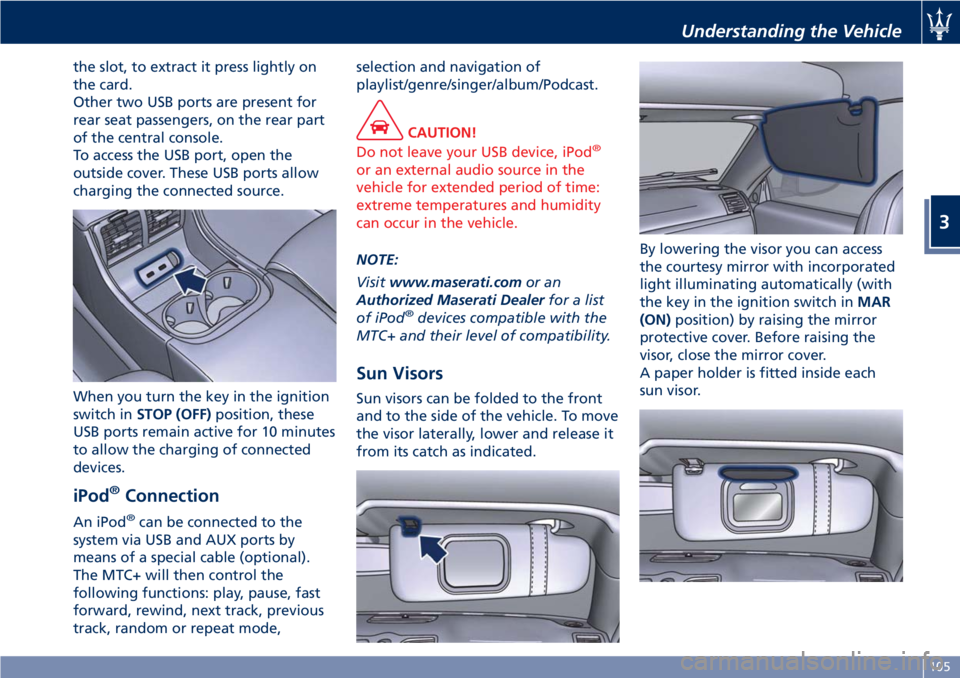
Sun Visors
Sun visors can be folded to the front
and to the side of the vehicle. To move
the visor laterally, lower and release it
from its catch as indicated.By lowering the visor you can access
the courtesy mirror with incorporated
light illuminating automatically (with
the key in the ignition switch inMAR
(ON)position) by raising the mirror
protective cover. Before raising the
visor, close the mirror cover.
A paper holder is fitted inside each
sun visor.
Understanding the Vehicle
3
105
Page 119 of 296
Calibration Selection
The driver can select, in relation to
road surface conditions, vehicle speed,
driving style and comfort, one of the
two calibration levels provided by the
system: normal or sports-style.
•Normal calibration, active when
SPORT drive mode is disabled
("SPORT" button not pressed), favors
comfort and higher driving stability
with low and average grip
conditions.
•Sport-style calibration, active when
SPORT drive mode is enabled
("SPORT" button pressed) , favors
wheel drive and permits a
dynamic-style driving with optimal
road holding.
Whenever the engine is started, the
system automatically activates
NORMAL drive mode, even if SPORT
drive mode was selected before the
engine was last turned off.
The sport-style calibration can be
selected only with the key in the
ignition switch inMAR (ON)position
and it is enabled by pressing button
"SPORT", even while driving.
When SPORT drive mode is activated,
the word “SPORT” on the instrument
cluster display and the LED on the
button illuminate.WARNING!
SPORT drive mode should not be
activated if the road surface is rough
or slippery.
The electronic suspension control
system works in combination with the
ESC system.
When the suspension is set to normal
calibration, stability is increased under
medium and low grip conditions,
while when it is set to sport-style
calibration, the ESC system optimizes a
sportier driving.
WARNING!
In low- and medium-grip conditions
(e.g., rain, snow, ice, sand, etc.) it is
advisable not to use SPORT drive
mode, even with the ESC system
enabled.
Malfunction Indicators
If one or more electric components in
the system prove to be malfunctioning
while driving, the ECU illuminates the
amber warning light accompanied
by the message “Check suspensions”
on the display. In addition, the ECU
calibrates the shock absorbers to apreset value, thus ensuring a safe
vehicle set up.
Should the malfunction involve one
shock absorber only, this will no
longer be controlled by the ECU and
will therefore remain set as it was
when the fault occurred. It is
therefore possible for one of the four
shock absorbers to work with a fixed
calibration, different from that of the
other ones.
In any case, safe and secure vehicle
driving is always ensured at low
speeds.
CAUTION!
In the event of a malfunction in the
suspension control electronic system,
which will be indicated by the
illumination of the amber warning
light on the display while driving,
keep a moderate speed and have the
vehicle checked as soon as possible by
anAuthorized Maserati Dealer.
If a malfunction occurs while driving,
and this is signaled by the illumination
of the
amber warning light on the
display, it is advisable to stop the
vehicle as soon as possible, turn the
key in the ignition switch toSTOP
(OFF)position and then restart the
engine.
Understanding the Vehicle
3
115