2020 MASERATI GRANTURISMO CONVERTIBLE ignition
[x] Cancel search: ignitionPage 252 of 296
(Continued)
quick coupling from the negative
pole (–) of the battery.
If the battery needs to be removed
from its compartment, you must first
detach the terminal clamp from
negative pole (–) and then the other
terminal clamp from positive pole (+),
after removing the protective cover.
Battery poles are marked positive (+)
and negative (–) and are identified on
the battery case.
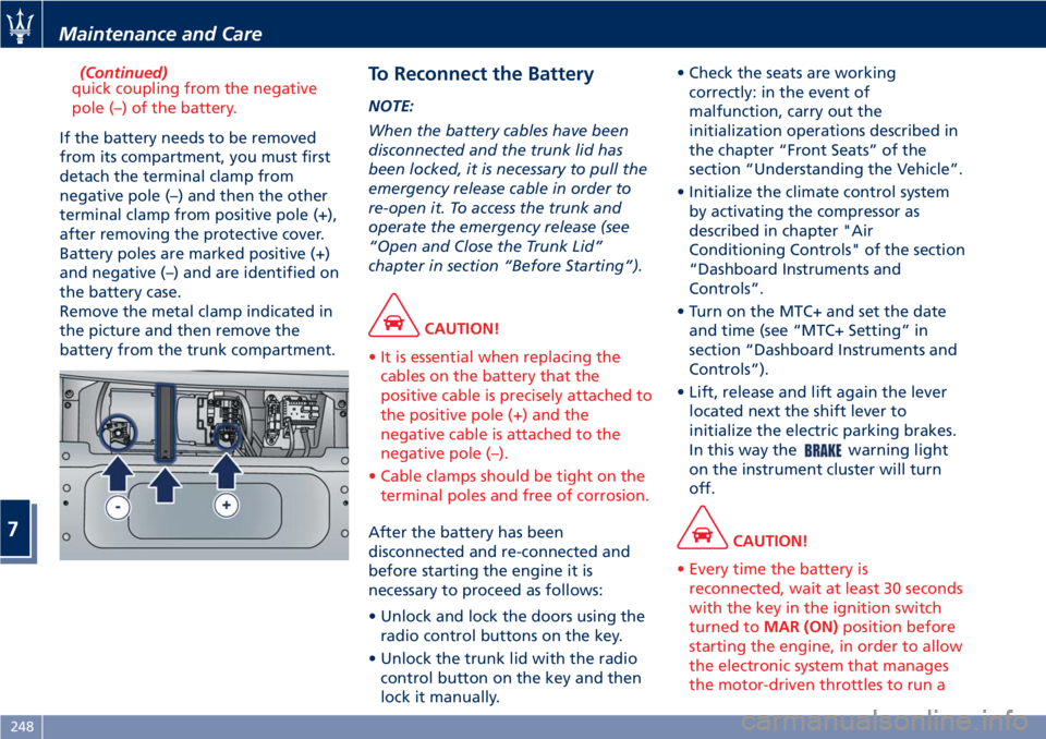
Remove the metal clamp indicated in
the picture and then remove the
battery from the trunk compartment.
To Reconnect the Battery
NOTE:
When the battery cables have been
disconnected and the trunk lid has
been locked, it is necessary to pull the
emergency release cable in order to
re-open it. To access the trunk and
operate the emergency release (see
“Open and Close the Trunk Lid”
chapter in section “Before Starting”).
CAUTION!
• It is essential when replacing the
cables on the battery that the
positive cable is precisely attached to
the positive pole (+) and the
negative cable is attached to the
negative pole (–).
• Cable clamps should be tight on the
terminal poles and free of corrosion.
After the battery has been
disconnected and re-connected and
before starting the engine it is
necessary to proceed as follows:
• Unlock and lock the doors using the
radio control buttons on the key.
• Unlock the trunk lid with the radio
control button on the key and then
lock it manually.• Check the seats are working
correctly: in the event of
malfunction, carry out the
initialization operations described in
the chapter “Front Seats” of the
section “Understanding the Vehicle”.
• Initialize the climate control system
by activating the compressor as
described in chapter "Air
Conditioning Controls" of the section
“Dashboard Instruments and
Controls”.
• Turn on the MTC+ and set the date
and time (see “MTC+ Setting” in
section “Dashboard Instruments and
Controls”).
• Lift, release and lift again the lever
located next the shift lever to
initialize the electric parking brakes.
In this way the
warning light
on the instrument cluster will turn
off.
CAUTION!
• Every time the battery is
reconnected, wait at least 30 seconds
with the key in the ignition switch
turned toMAR (ON)position before
starting the engine, in order to allow
the electronic system that manages
the motor-driven throttles to run a
Maintenance and Care
7
248
Page 253 of 296
self-learning cycle. At the same time,
you can run the date and time set up
procedure for the MTC.
• Every time the battery is
reconnected the
and
warning lights will flash for
about 10 seconds and then go off.
WARNING!
California Proposition 65
Operating, servicing and maintaining
a passenger vehicle or off-road vehicle
can expose you to chemicals including
such as, engine exhaust, carbon
monoxide, phthalates and lead, that
which are know to the State of
California to cause cancer and birth
defects or other reproductive harm. To
minimize exposure, avoid breathing
exhaust, do not idle the engine except
as necessary, service your vehicle in a
well-ventilated area and wear gloves
or wash your hands frequently when
servicing your vehicle. For more
information go to:
www.P65Warnings.ca.gov/passenger-
vehicle
Useful Advice to Extend
Battery Life
When parking the vehicle, make sure
that the doors, front, rear lids and
flaps are properly closed. All interior
lights should be off.
When the engine is turned off, do not
keep the connected devices switched
on for a long time (such as radio,
hazard warning flashers, fan, etc.).
CAUTION!
If the battery charge remains below
50% for a long period of time, it will
be damaged due to sulfation; its
performance and starting power will
be reduced and it will be more subject
to freezing (this can happen even at
14°F/-10°C).
We recommend you to have the
battery charge condition checked,
preferably at the beginning of the
cold season, to prevent the electrolyte
from freezing.
This check should be carried out more
frequently if the vehicle is used mainly
for short trips or if it is equipped with
power absorbing devices that remain
permanently on even when the
ignition switch is off. This appliesabove all if these devices have been
retrofitted ("Aftermarket" services).
If the vehicle is not used for long
periods of time, please see “Vehicle
Stored for Long Periods” in this
section.
Battery Recharge
WARNING!
The process of charging or recharging
the battery produces hydrogen, a
flammable gas that can explode and
cause serious injuries. When charging
or recharging the battery, follow the
recommended precautions at all
times.
•Before using a charger device
always check that this tool is
suitable for the installed battery,
with constant voltage (lower than
14.8 V) and low amperage
(maximum limit 15 A).
•Recharge the battery in a
well-ventilated environment.
•Never charge or recharge a frozen
battery: it can explode due to
hydrogen trapped inside the ice
crystals.
•Ensure that any sparks or open
(Continued)
Maintenance and Care
7
249
Page 257 of 296
Pos.Amp. –
ColorSystem /
Component
F04Maxi 40 A –
OrangeABS cylinder
F05Maxi 40 A –
OrangeA.C. Node
F06Maxi 60 A –
BlueFan 2 relay
F0730A–
GreenT07 I.E. main
relay
F087.5A–
BrownT08 - Air
conditioner
compressor
relay
F097.5A–
BrownT05 stop light
control relay
F10 15 A – Blue T06 horn relay
F11 10 A – Red LH high-beam
F147.5A–
BrownThird stop
F15 15 A – BlueAlternator
sensing
F16 10 A – Red LH spot light
F17 10 A – Red RH high-beam
F187.5A–
BrownI.E. bank
F19 7.5 A – BlueT02 DRL lights
relayPos.Amp. –
ColorSystem /
Component
F20 10 A – RedT17 Key lock
solenoid relay
F21 - Not used
F22 - Not used
F23 10 A – Red ABS Electronics
F24 10 A – Red RH spot light
F3030A–
GreenT20 ignition
relay
F81Maxi 50 A –
RedCPL2
F82 - Not used
F83Maxi 50 A –
RedAir pump relay
F8420A–
YellowIgnition switch.
F8530A–
GreenHeadlight
washers
F87 - Not used
F88 15 A – BlueMain
injector/coil
relay - cylinders
1-4
F89 15 A – BlueMain
injector/coil
relay - cylinders
5-8Pos.Amp. –
ColorSystem /
Component
F90 15 A – BlueMain I.E. relay,
secondary
connected
devices
F91 10 A – RedMain relay, I.E.
ECU
F92 15 A – BlueMain relay,
oxygen sensors
F93 - Not used
F947.5A–
BrownNCS
F957.5A–
BrownCSG
F967.5A–
BrownAlternator
F97 10 A – Red I.E. ECU
F98 - Not used
F99 - Not used
F100 - Not used
F101 - Not used
F102 - Not used
F103 - Not used
F104 - Not used
F105 - Not used
F106 - Not used
Maintenance and Care
7
253
Page 261 of 296

Bulb Replacement
The signal failure of an external light
(turn signal, low beam and high beam,
license plate light, reverse light, brake
light and rear fog light) is
communicated to the instrument
cluster that displays on the TFT screen
the
oramber warning light
and a text message indicating which
light is faulty.
Front Headlights
The light bulbs of the headlight
clusters are arranged as follows:
1Bi-Xenon low-beam/high-beam
bulb.
2Position light and DRL (*) LED.
3Turn signal light bulb.
4FTP bulb, headlight flashing.
5Side marker bulb.
(*) On vehicles for the Canadian
market DRL are always enabled.
CAUTION!
Due to the complexity of the
operation, for the replacement of the
headlight clusters light bulbs, we
recommend that you contact an
Authorized Maserati Dealer.
WARNING!
The headlamps are a type of high
voltage discharge tube. High voltage
can remain in the circuit even with the
headlamp switch and the ignition
switch off. Because of this, you should
not attempt to replace a headlamp
bulb yourself, but take the vehicle to
an Authorized Maserati Dealer for
service.
Tail-Light Clusters Light Bulbs
The taillight bulbs are arranged as
follows:
1Position light guide LED.
2Stop light LED.
3Turn signal LED.
4Reverse light bulb.
5Rear fog light bulb.
Tail-Light Clusters Bulbs
Replacement
Most of the lamps of the taillight are
LED powered and cannot be replaced
individually. The only exceptions are
the reverse and the rear fog light
bulbs for which you find below the
replacement procedure.
Contact anAuthorized Maserati
Dealerto locate the correct parts and
replace them.
Maintenance and Care
7
257
Page 273 of 296
Vehicle Stored for Long
Periods
If the vehicle is going to be stored for
over a month, follow the below
precautions:
• Wash and dry the vehicle
thoroughly.
• Store the vehicle in a covered, dry
and, if possible, ventilated area.
• Select P (Park) and turn off the
engine.
• Turn the key in the ignition switch in
STOP (OFF)position.
• Disconnect the battery (refer
“Maintenance-Free Battery” in this
section) or connect a battery charger
(refer to paragraph “Maintaining
Battery Charge” of chapter “Battery
Statement” in this section).
• Check the battery charge status.
During parking, this check must be
carried out every three weeks.
Recharge the battery if the open
circuit voltage is lower than 12.2 V.
• Check that the parking brake is NOT
engaged.
• Do not empty the engine cooling
system.
• Clean and protect the painted parts
applying protective wax.• Clean and protect polished metal
parts with special products available
on the market.
• Talc the windshield wiper blades and
raise them from the windshield.
• Cover the vehicle with a long cloth
in breathable fabric (available from
theAuthorized Maserati Dealer). Do
not use thick plastic sheets, which do
not allow the humidity on the
vehicle surface to evaporate.
• Inflate the tires up to a pressure
which must be 1 bar (14.5 psi) higher
than the normally prescribed one,
and check it at regular intervals.
NOTE:
TheAuthorized Maserati Dealercan
provide you with any information
about the available “Indoor and
Outdoor Car Covers”, available in the
“Genuine Accessories” range.
WARNING!
The tire pressure must be brought
back to the prescribed value before
reusing the vehicle (see “Tire Inflation
Pressure” in section “Features and
Specifications”).
Restarting the Vehicle
Before restarting the vehicle after a
long period of inactivity, we
recommend that you carry out the
following operations.
• Check the tires for pressure and for
any damages, cuts or cracks. If this is
the case, have them replaced.
• Do not dry-rub the external surface
of the vehicle.
• Visually inspect if there are any fluid
leaks (oil, brake and clutch fluid,
engine coolant etc.).
• Have the engine oil and filter
replaced.
• Check the fluid levels in the brake
system, as well as the engine coolant
level.
• Check the air filter and have them
replaced if necessary.
• Reconnect the battery after checking
the charge status (refer to
“Maintenance-Free Battery” in this
section) and perform the initializing
procedure if applicable.
• With the transmission in N (Neutral),
let the engine idle for several
minutes.
Maintenance and Care
7
269
Page 274 of 296
WARNING!
The engine idle must be performed
outdoors. Exhaust gases contain
carbon monoxide which is strongly
toxic and potentially lethal.
WARNING!
California Proposition 65
Operating, servicing and maintaining
a passenger vehicle or off-road vehicle
can expose you to chemicals including
such as, engine exhaust, carbon
monoxide, phthalates and lead, that
which are know to the State of
California to cause cancer and birth
defects or other reproductive harm. To
minimize exposure, avoid breathing
exhaust, do not idle the engine except
as necessary, service your vehicle in a
well-ventilated area and wear gloves
or wash your hands frequently when
servicing your vehicle. For more
information go to:
www.P65Warnings.ca.gov/passenger-
vehicle
Battery Statement
Battery Statement Status of
Charge
To avoid problems with ignition and/or
the electrical system in general when
you are driving, the battery charge
status is constantly maintained and
guaranteed by the vehicle's recharge
circuit; the main component of which
is the alternator. This circuit is only
able to supply voltage to the battery
when the vehicle is traveling.
The
warning light on the
instrument cluster (see “Instrument
Cluster” in section “Dashboard
Instruments and Controls”), will
indicate any malfunctions in the
recharge circuit or an insufficient
battery charge status (flashing).
The vehicle is fitted with advanced
electronic systems, such as, for
example, the alarm system and various
electronic control modules, which
consume power even when the key in
the ignition switch is in theSTOP (OFF)
position and the vehicle is not being
used.
Therefore, it is fundamental that the
battery is properly charged to ensure
that the engine starts properly andthat all the electrical/electronic systems
in the vehicle work efficiently.
Maintaining Battery Charge
If you perform short daily trips
(approximately 10 miles/16 km), which
correspond to an annual total of 4000
miles/6000 km, or when the vehicle is
not going to be used for one week or
more, Maserati recommends
connecting the vehicle to a battery
charger, to save you the trouble of
having to recharge the battery (see
“Battery Charge Maintainer
Operation” in this chapter).
The battery charge maintainer will
keep the battery charged properly and
at the correct voltage levels required
by the systems and devices in the
vehicle.
Before using the battery charge
maintainer, carefully follow the
instructions provided.
If you do not use a battery charge
maintainer to prevent the battery
from going dead when you are not
going to use the vehicle for long
periods of time, you need to check and
recharge the battery at least once
every three weeks. Make this check if
you perform short daily trips
(approximately 10 mi/16 km) which
correspond to an annual total of 4000
Maintenance and Care
7
270
Page 275 of 296
miles/6000 km. Please note that
allowing the battery to go dead
repeatedly can cause premature wear
on the internal cells and greatly
reduce their life, leading to problems
with the ignition system and other
electrical/electronic systems.
TheAuthorized Maserati Dealeris
available to advise you on how to
recharge your battery correctly and
give you useful information on battery
care and maintenance.
NOTE:
TheAuthorized Maserati Dealercan
provide you with any information
about the Maserati approved “Battery
Charger and Conditioner”, available in
the “Genuine Accessories” range.
WARNING!
The process of charging or recharging
the battery produces hydrogen, a
dangerous gas that can explode and
cause serious injuries. When charging
or recharging the battery, follow the
recommended precautions at all
times:
•always charge or recharge the
battery in a well-ventilated
environment;•never charge or recharge a battery
that has frozen: it can explode due
to hydrogen trapped inside the ice
crystals;
•ensure that any sparks or open
flames are nowhere near the battery
while it is charging;
•before using a charger to charge or
maintain the battery charge status,
carefully follow the instructions
provided to ensure the charger is
connected to the battery safely and
correctly.
Battery Charge Maintainer
Operation
Charge Maintainer Socket
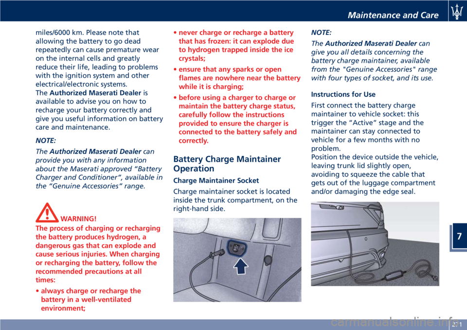
Charge maintainer socket is located
inside the trunk compartment, on the
right-hand side.NOTE:
TheAuthorized Maserati Dealercan
give you all details concerning the
battery charge maintainer, available
from the "Genuine Accessories" range
with four types of socket, and its use.
Instructions for Use
First connect the battery charge
maintainer to vehicle socket: this
trigger the “Active” stage and the
maintainer can stay connected to
vehicle for a few months with no
problem.
Position the device outside the vehicle,
leaving trunk lid slightly open,
avoiding to squeeze the cable that
gets out of the luggage compartment
and/or damaging the edge seal.
Maintenance and Care
7
271
Page 284 of 296

Engine Data
Cylinder number and position 8 - 90° V
Number of valves per cylinder 4
Bore x stroke 94 x 84,5 mm
Total displacement 4691 cu.cm
Compression ratio 11.2 +/- 0.2 : 1
Maximum power output (EC) (*) 338 kW – 460 CV
- corresponding rpm 7000 rpm
Maximum torque (EC) 520 Nm – 53 kgm
- corresponding rpm 4750 rpm
(*) Values obtained in SPORT drive mode with 98 R.O.N.
Timing SystemThe timing system uses two overhead camshafts. The
camshafts are equipped with timing variator. The timing
control is done by two chains.
Lubrication
SystemThe lubrication system is controlled by the wet sump system
through an oil pump and the relative suction screen,
incorporated in the crankcase.
Cooling SystemEngine cooling is ensured by an anti-freeze mixture
circulating inside a circuit equipped with radiator,
centrifugal pump and expansion tank.
Injection –
Ignition SystemHigh-pressure direct fuel injection system. Static ignition
with digital electronic control system included and
controlled by a single microprocessor ECU.
Features and Specifications
8
280