2020 LEXUS RX350 battery
[x] Cancel search: batteryPage 1 of 516

RX350_RX350L_U
1
2
3
4
5
6
7
8
9
Pictorial indexSearch by illustration
For safety
and securityMake sure to read through them
(Main topics: Child seat, theft deterrent system)
Vehicle status
information and
indicatorsReading driving-related information
(Main topics: Meters, multi-information display)
Before drivingOpening and closing the doors and windows,
adjustment before driving
(Main topics: Keys, doors, seats)
DrivingOperations and advice which are necessary for driving
(Main topics: Starting engine, refueling)
Interior featuresUsage of the interior features
(Main topics: Air conditioner, storage features)
Maintenance
and careCaring for your vehicle and maintenance procedures
(Main topics: Interior and exterior, light bulbs)
When trouble
arisesWhat to do in case of malfunction and emergency
(Main topics: Battery discharge, flat tire)
Vehicle
specificationsVehicle specifications, customizable features
(Main topics: Fuel, oil, tire inflation pressure)
For ownersReporting safety defects for U.S. owners, and seat belt,
SRS airbag and headlight aim instructions for Canadian
owners
IndexSearch by symptom
Search alphabetically
Page 4 of 516

4TABLE OF CONTENTS
6-1. Maintenance and careCleaning and protecting the vehi-cle exterior ................................... 350
Cleaning and protecting the vehi- cle interior .................................... 353
6-2. Maintenance Maintenance requirements ..... 356
General maintenance ................ 357
Emission inspection and mainte- nance (I/M) programs ............ 360
6-3. Do-it-yourself maintenance Do-it-yourself service precautions............................................................ 361
Hood.................................................. 363
Positioning a floor jack............... 363
Engine compartment.................. 365
Tires .................................................... 371
Tire inflation pressure ................. 383
Wheels.............................................. 384
Air conditioning filter..................386
Windshield wiper inserts........... 388
Electronic key battery ................ 389
Checking and replacing fuses ............................................................ 391
Headlight aim................................. 392
Light bulbs ....................................... 394
7-1. Essential information Emergency flashers..................... 404
If your vehicle has to be stopped in an emergency ............................. 404If the vehicle is trapped in rising
water .............................................. 405
7-2. Steps to take in an emergency If your vehicle needs to be towed.......................................................... 407
If you think something is wrong ............................................................. 411
Fuel pump shut off system .......... 412
If a warning light turns on or a warn- ing buzzer sounds....................... 413
If a warning messa ge is displayed
........................................................... 422
If you have a flat tire .................... 426
If the engine will not start .......... 438
If you lose your keys.................... 440
If the fuel filler door cannot be opened .......................................... 440
If the electronic key does not oper- ate properly ................................... 441
If the vehicle battery is discharged .......................................................... 443
If your vehicle overheats ........... 447
If the vehicle becomes stuck ... 449
8-1. Specifications Maintenance data (fuel, oil level, etc.) ................................................. 452
Fuel information............................ 459
Tire information ............................. 461
8-2. Customization Customizable features .............. 470
8-3. Initialization Items to initialize ........................... 483
6Maintenance and care
7When trouble arises
8Vehicle specifications
Page 67 of 516

671-4. Theft deterrent system
1
For safety and security
■Items to check before locking the
vehicle
To prevent unexpected triggering of
the alarm and vehicle theft, make sure
of the following:
Nobody is in the vehicle.
The windows, moon roof (if
equipped) and panoramic moon
roof (if equipped) are closed before
the alarm is set.
No valuables or other personal
items are left in the vehicle.
■Setting
Close the doors and hood, and lock all
the doors. The system will be set auto-
matically after 30 seconds.
The indicator light changes from being on
to flashing when the system is set.
■Canceling or stopping
Do one of the following to deactivate
or stop the alarm:
Unlock the doors.
Turn the engine switch to ACCES-
SORY or IGNITION ON mode, or
start the engine. (The alarm will be
deactivated or stopped after a few
seconds.)
■System maintenance
The vehicle has a maintenance-free type
alarm system.
■Triggering of the alarm
The alarm may be triggered in the following
situations:
(Stopping the alarm deactivates the alarm
system.)
●A person inside the vehicle opens a door
or hood, or unlocks the vehicle.
●The battery is recharged or replaced
when the vehicle is locked. ( P.445)
Alarm
The alarm uses light and sound to
give an alert when an intrusion is
detected.
The alarm is triggered in the follow-
ing situations when the alarm is set:
A locked door is unlocked or
opened in any way other than
using the entry function, wireless
remote control or mechanical
key. (The doors will lock again
automatically.)
The hood is opened.
Setting/canceling/stopping the
alarm system
Page 82 of 516

822-1. Instrument cluster
The greater the number of segments
displayed, the greater the driving force
applied.
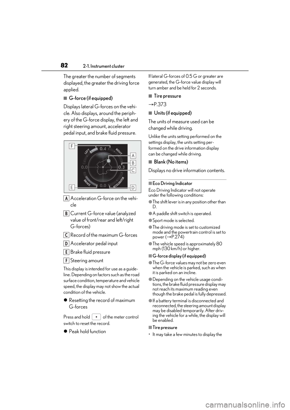
■G-force (if equipped)
Displays lateral G-forces on the vehi-
cle. Also displays, around the periph-
ery of the G-force display, the left and
right steering amount, accelerator
pedal input, and brake fluid pressure.
Acceleration G-force on the vehi-
cle
Current G-force value (analyzed
value of front/rear and left/right
G-forces)
Record of the maximum G-forces
Accelerator pedal input
Brake fluid pressure
Steering amount
This display is intended for use as a guide-
line. Depending on factors such as the road
surface condition, temperature and vehicle
speed, the display may not show the actual
condition of the vehicle.
Resetting the record of maximum
G-forces
Press and hold of the meter control
switch to reset the record.
Peak hold function
If lateral G-forces of 0.5 G or greater are
generated, the G-forc e value display will
turn amber and be held for 2 seconds.
■Tire pressure
P.373
■Units (if equipped)
The units of measure used can be
changed while driving.
Unlike the units sett ing performed on the
settings display, th e units setting per-
formed on the drive information display
can be changed while driving.
■Blank (No items)
Displays no drive information contents.
■Eco Driving Indicator
Eco Driving Indicator will not operate
under the following conditions:
●The shift lever is in an y position other than
D.
●A paddle shift swit ch is operated.
●Sport mode is selected.
●The driving mode is set to customized
mode and the powertrain control is set to
power (P.274)
●The vehicle speed is approximately 80
mph (130 km/h) or higher.
■G-force display (if equipped)
●The G-force values may not be zero even
when the vehicle is parked, such as when
it is parked on an incline.
●Depending on the vehicle usage condi-
tions, the brake fluid pressure display may
not reach its maximum reading even
though the brake pedal is fully depressed.
●If a battery terminal is disconnected and
reconnected, the steeri ng amount display
may be disabled temporarily. After driv-
ing the vehicle for a while, the display will
be enabled.
■Tire pressure
• It may take a few minutes to display the
A
B
C
D
E
F
Page 84 of 516

842-1. Instrument cluster
Select to set the tachometer needle color.
Rev indicator (F SPORT models)
( P.76)
• Select to enable/disable the Rev indica-
tor.
• Select to set the desired engine speed at which the Rev indicator will begin to be
displayed.
Selectable engine speed range:
2000 rpm to 6500 rpm
Rev peak (F SPORT models)
( P.77)
Select to enable/dis able the Rev peak.
Default setting
Select to reset the meter display settings to
the default setting.
■Vehicle functions and settings that
can be changed
P.470
■Background color of the indicator/shift
position display area (except F SPORT
models)
The background color of the indicator/shift
position display area is changed according
to the driving mode as follows ( P.274):
●Eco drive mode: Blue
●Sport mode: Red
■Suspension of the settings display
●Some settings cannot be changed while
driving. When changi ng settings, park
the vehicle in a safe place.
●If a warning message is displayed, opera-
tion of the settings display will be sus-
pended.
Displays suggestions to the driver in
the following situations. To select a
response to a displayed suggestion,
use the meter control switches.
■Suggestion to enable the power
back door
If the power back door system is dis-
abled (setting on set to off) and the
power back door switch on the instru-
ment panel is operated, a suggestion
message will be displayed asking if you
wish to enable the power back door
system.
To enable the power back door system,
select “Yes”.
After enabling the power back door sys-
tem, press the power back door switch
again to open or close the power back
door.
WARNING
■Cautions during setting up the dis-
play
As the engine needs to be running
during setting up the display, en sure that
the vehicle is parked in a place with ade-
quate ventilation. In a closed area such as
a garage, exhaust gases including harm-
ful carbon monoxide (CO) may collect
and enter the vehicle. This may lead to
death or a serious health hazard.
NOTICE
■While setting up the display
To prevent battery discharge, ensure that
the engine is running while setting up the
display features.
Suggestion function
Page 88 of 516

882-1. Instrument cluster
■Changing settings of the head-up
display
Select on the multi-information
display ( P.470) to change the fol-
lowing settings:
Display brightness/position
Select to adjust the brightness and position
of the head-up display.
Display content
Select to enable/dis able the following
items:
• Route guidance to destination (if equipped)
• Driving assist system status (if equipped)
• Compass (if equipped)
• Audio system operation status
Eco Driving Indicator/Tachometer
Select to display Eco Driving Indica-
tor/tachometer/no content.
Display angle
Select to adjust the angle of the head-up
display.
■Enabling/disabling of the head-up dis-
play
If the head-up display is disabled, it will
remain disabled when the engine switch is
turned off then back to IGNITION ON
mode.
■Display brightness
The brightness of the head-up display can
be adjusted on of the multi-information
display. Also, it is automatically adjusted
according to the ambient brightness.
■Automatic adjustment of the head-up
display position (if equipped)
A desired head-up display position can be
entered to memory and recalled automati-
cally by the driving position memory sys-
tem. ( P.134)
■When the battery is disconnected
The customize settings of the head-up dis-
play will be reset.
Displays the following multi-informa-
tion display linked icons:
: Master warning icon
Displayed when a warn ing message is dis-
played on the multi-information display.
WARNING
■Caution for changing settings of the
head-up display
As the engine needs to be running while
changing the settings of the head-up dis-
play, ensure that the vehicle is parked in a
place with adequate ventilation. In a
closed area such as a garage, exhaust
gases including harmful carbon monox-
ide (CO) may collect and enter the vehi-
cle. This may lead to death or a serious
health hazard.
NOTICE
■When changing the settings of the
head-up display
To prevent battery discharge, ensure that
the engine is running while the changing
the settings of the head-up display.
Information icon/Master warn-
ing icon
Page 94 of 516

943-1. Key information
3-1.Key information
The following keys are provided with
the vehicle.
Electronic keys
• Operating the smart access system with push-button start ( P.113)
• Operating the wireless remote control function ( P.95)
Mechanical keys
Key number plate
■When riding in an aircraft
When bringing an elec tronic key onto an
aircraft, make sure you do not press any
buttons on the electronic key while inside
the aircraft cabin. If you are carrying an
electronic key in your bag, etc., ensure that
the buttons are not likely to be pressed acci-
dentally. Pressing a button may cause the
electronic key to em it radio waves that
could interfere with the operation of the air-
craft.
■Electronic key battery depletion
●The standard battery life is 1 to 2 years.
●If the battery becomes low, an alarm will
sound in the cabin when the engine is
stopped.
●To reduce key battery depletion when the
electronic key is to not be used for long
periods of time, set the electronic key to
the battery-saving mode. ( P.114)
●As the electronic key always receives
radio waves, the battery will become
depleted even if the electronic key is not
used. The following symptoms indicate
that the electronic key battery may be
depleted. Replace the battery when nec-
essary.
• The smart access system with push-but- ton start or the wireless remote control
does not operate.
• The detection area becomes smaller.
• The LED indicator on the key surface does not turn on.
●To avoid serious dete rioration, do not
leave the electronic key within 3 ft. (1 m)
of the following electrical appliances that
produce a magnetic field:
•TVs
• Personal computers
• Cellular phones, cordless phones and battery chargers
• Recharging cellular phones or cordless
phones
•Table lamps
• Induction cookers
■Replacing the battery
P.389
■Confirmation of the registered key
number
The number of keys already registered to
the vehicle can be confirmed. Ask your
Lexus dealer for details.
■If “A New Key has been Registered
Contact Your Dealer for Details” is
shown on the multi-information display
This message will be displayed each time
the driver’s door is opened when the doors
are unlocked from the outside for approxi-
mately one week after a new electronic key
has been registered.
If this message is disp layed but you have not
had a new electronic key registered, ask
your Lexus dealer to check if an unknown
electronic key (other than those in your
possession) has be en registered.
Keys
The keys
A
B
C
Page 96 of 516

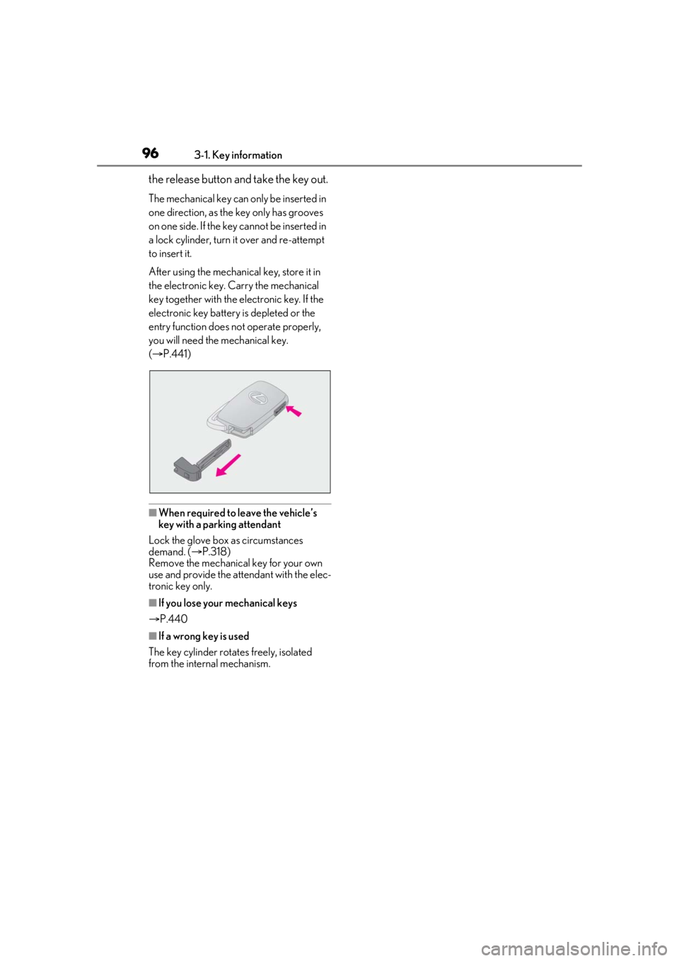
963-1. Key information
the release button and take the key out.
The mechanical key can only be inserted in
one direction, as the key only has grooves
on one side. If the key cannot be inserted in
a lock cylinder, turn it over and re-attempt
to insert it.
After using the mechanical key, store it in
the electronic key. Carry the mechanical
key together with the electronic key. If the
electronic key battery is depleted or the
entry function does not operate properly,
you will need the mechanical key.
( P.441)
■When required to leave the vehicle’s
key with a parking attendant
Lock the glove box as circumstances
demand. ( P.318)
Remove the mechanical key for your own
use and provide the attendant with the elec-
tronic key only.
■If you lose your mechanical keys
P.440
■If a wrong key is used
The key cylinder rotates freely, isolated
from the internal mechanism.