Page 520 of 604

737
Maintenance
✽ ✽NOTICE
If you connect unauthorized elec-
tronic devices to the battery, the bat-
tery may be discharged. Never use
unauthorized devices.
Battery recharging
Your vehicle has a maintenance-free,
calcium-based battery.
If the battery becomes discharged
in a short time (because, for exam-
ple, the headlights or interior lights
were left on while the vehicle was
not in use), recharge it by slow
charging (trickle) for 10 hours.
If the battery gradually discharges because of high electric load while
the vehicle is being used, recharge
it at 20-30A for two hours.
Recharging battery
When recharging the battery,
observe the following precautions:
The battery must be removed fromthe vehicle and placed in an area
with good ventilation.
Do not allow cigarettes, sparks, or flame near the battery.
Watch the battery during charging, and stop or reduce the charging
rate if the battery cells begin
gassing (boiling) violently or if the
temperature of the electrolyte of
any cell exceeds 49°C (120°F).
Wear eye protection when check- ing the battery during charging.
Disconnect the battery charger in the following order.
1. Turn off the battery charger main switch.
2. Unhook the negative clamp from the negative battery terminal.
3. Unhook the positive clamp from the positive battery terminal.WARNING- Risk of elec-
trocution
Never touch the electrical igni-
tion system while the vehicle is
running. This system works
with high voltage which can
shock you.
WARNING- Recharging Battery
Never attempt to recharge the
battery when the battery cables
are connected.
WARNING- Battery lead
compound
Battery posts, terminals, and
related accessories contain
lead and lead compounds.
Wash hands after handling.
Page 521 of 604
Maintenance
38
7
Before performing maintenance or
recharging the battery, turn off all
accessories and stop the engine.
The negative battery cable must be removed first and installed last
when the battery is disconnected.Reset items
Items should be reset after the bat-
tery has been discharged or the bat-
tery has been disconnected.
Auto up/down window
Sunroof
Trip computer
Climate control system
Clock
Audio
Page 533 of 604

Maintenance
50
7
Pneumatic tire: A mechanical
device made of rubber, chemicals,
fabric and steel or other materials,
that, when mounted on an automo-
tive wheel, provides the traction and
contains the gas or fluid that sustains
the load.
Production options weight: The
combined weight of installed regular
production options weighing over 5
lb.(2.3 kg) in excess of the standard
items which they replace, not previ-
ously considered in curb weight or
accessory weight, including heavy
duty brakes, ride levelers, roof rack,
heavy duty battery, and special trim.
Recommended Inflation Pressure:
Vehicle manufacturer's recommend-
ed tire inflation pressure and shown
on the tire placard.
Radial Ply Tire: A pneumatic tire in
which the ply cords that extend to the
beads are laid at 90 degrees to the
centerline of the tread.
Rim: A metal support for a tire and
upon which the tire beads are seated. Sidewall:
The portion of a tire
between the tread and the bead.
Speed Rating: An alphanumeric
code assigned to a tire indicating the
maximum speed at which a tire can
operate.
Traction: The friction between the
tire and the road surface. The
amount of grip provided.
Tread: The portion of a tire that
comes into contact with the road.
Treadwear Indicators: Narrow
bands, sometimes called "wear bars,"
that show across the tread of a tire
when only 2/32 inch of tread remains.
UTQGS: Uniform Tire Quality
Grading Standards, a tire information
system that provides consumers with
ratings for a tire's traction, tempera-
ture and treadwear. Ratings are
determined by tire manufacturers
using government testing proce-
dures. The ratings are molded into
the sidewall of the tire. Vehicle Capacity Weight:
The num-
ber of designated seating positions
multiplied by 68 kg (150 lbs.) plus the
rated cargo and luggage load.
Vehicle Maximum Load on the
Tire: Load on an individual tire due
to curb and accessory weight plus
maximum occupant and cargo
weight.
Vehicle Normal Load on the Tire:
Load on an individual tire that is
determined by distributing to each
axle its share of the curb weight,
accessory weight, and normal occu-
pant weight and driving by 2.
Vehicle Placard: A label permanent-
ly attached to a vehicle showing the
original equipment tire size and rec-
ommended inflation pressure.
Page 536 of 604

753
Maintenance
FUSES
A vehicle’s electrical system is pro-
tected from electrical overload dam-
age by fuses.
This vehicle has 2 (or 3) fuse panels,
one located in the driver’s side panel
bolster, the other in the engine com-
partment near the battery.
If any of your vehicle’s lights, acces-
sories, or controls do not work, check
the appropriate circuit fuse. If a fuse
has blown, the element inside the
fuse will melt.
If the electrical system does not
work, first check the driver’s side
fuse panel.
Always replace a blown fuse with
one of the same rating.
If the replacement fuse blows, this
indicates an electrical problem. Avoid
using the system involved and imme-
diately consult an authorized Kia
dealer.
Three kinds of fuses are used: bladetype for lower amperage rating, car-tridge type, and multi fuse for higheramperage ratings.
WARNING- Fuse replace-
ment
Never replace a fuse with any- thing but another fuse of the
same rating.
A higher capacity fuse could cause damage and possibly a
fire.
Never install a wire or alu- minum foil instead of the
proper fuse - even as a tem-
porary repair. It may cause
extensive wiring damage and
a possible fire.
Do not arbitrarily modify or add-on electric wiring of the
vehicle.
OYP074073N
Normal
Normal
■
Blade type
■ Cartridge type
■ Multi fuse Blown
Blown
Normal Blown
Page 537 of 604

Maintenance
54
7
✽ ✽
NOTICE
• When replacing a fuse, turn the
ignition “OFF” and turn off
switches of all electrical devices
then remove battery (-) terminal.
• The actual fuse/relay panel label may differ from equipped items.
CAUTION
Do not use a screwdriver or any
other metal object to removefuses because it may cause ashort circuit and damage thesystem.
WARNING- Electrical Fire
Always ensure replacements
fuses and relays are securely
fastened when installed. Failure
to do so can result in a vehicle
fire.
CAUTION
When replacing a blown fuse or relay, make sure the newfuse or relay fits tightly intothe clips. Failure to tightlyinstall the fuse or relay maycause damage to the wiringand electric systems.
Do not remove fuses, relays and terminals fastened withbolts or nuts. The fuses, relaysand terminals may not be fas-tened correctly which maycause vehicle damage.
CAUTION
Do not input any other objects except fuses or relays intofuse/relay terminals such as ascrewdriver or wiring. It maycause contact failure and sys-tem malfunction.
Do not plug in screwdrivers or aftermarket wiring into the ter-minal originally designed forfuse and relays only. The elec-trical system and wiring of thevehicle interior may be dam-aged or burned due to contactfailure.
If you directly connect the wire on the taillight or replacethe bulb which is over the reg-ulated capacity to install trail-ers etc., the inner junctionblock can get burned.
Page 538 of 604
755
Maintenance
✽ ✽NOTICE- Remodeling
Prohibited
Do not rewire your vehicle in any
way as doing so may affect the per-
formance of several safety features
in your vehicle. Rewiring your vehi-
cle may also void your warranty and
cause you to be responsible for any
subsequent vehicle damage which
may result.
✽ ✽ NOTICE- Window tinting pre-
caution
Window tint (especially metallic
film) might cause communication
errors or poor radio reception, and
malfunctioning automatic lighting
system due to reflections from the
mirror tint inside the vehicle. The
solution used might also leak into
the electronic components, causing
malfunctions or damage.
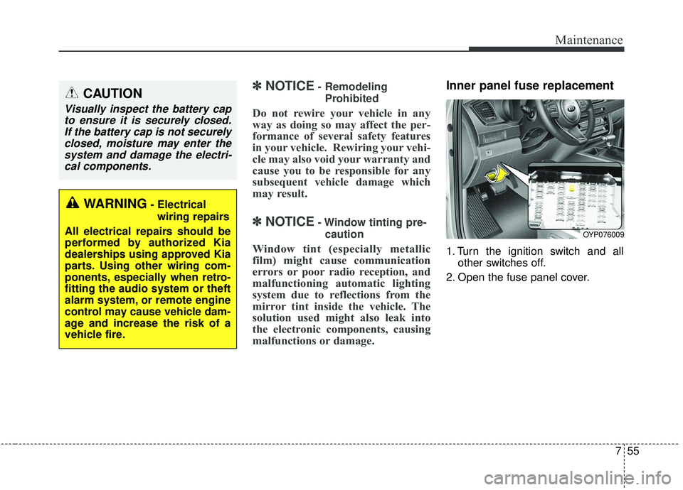
Inner panel fuse replacement
1. Turn the ignition switch and all other switches off.
2. Open the fuse panel cover.
CAUTION
Visually inspect the battery cap to ensure it is securely closed.If the battery cap is not securelyclosed, moisture may enter thesystem and damage the electri-cal components.
OYP076009
WARNING- Electrical
wiring repairs
All electrical repairs should be
performed by authorized Kia
dealerships using approved Kia
parts. Using other wiring com-
ponents, especially when retro-
fitting the audio system or theft
alarm system, or remote engine
control may cause vehicle dam-
age and increase the risk of a
vehicle fire.
Page 541 of 604
Maintenance
58
7
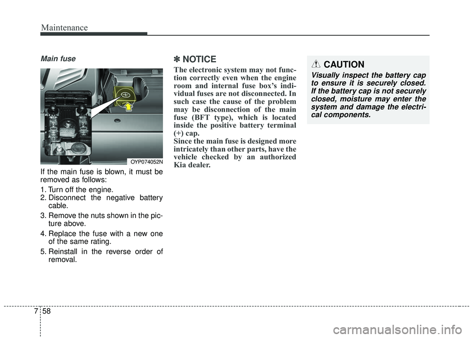
Main fuse
If the main fuse is blown, it must be
removed as follows:
1. Turn off the engine.
2. Disconnect the negative battery
cable.
3. Remove the nuts shown in the pic- ture above.
4. Replace the fuse with a new one of the same rating.
5. Reinstall in the reverse order of removal.
✽ ✽NOTICE
The electronic system may not func-
tion correctly even when the engine
room and internal fuse box’s indi-
vidual fuses are not disconnected. In
such case the cause of the problem
may be disconnection of the main
fuse (BFT type), which is located
inside the positive battery terminal
(+) cap.
Since the main fuse is designed more
intricately than other parts, have the
vehicle checked by an authorized
Kia dealer.
OYP074052N
CAUTION
Visually inspect the battery cap
to ensure it is securely closed.If the battery cap is not securelyclosed, moisture may enter thesystem and damage the electri-cal components.
Page 547 of 604

Maintenance
64
7
Fuse Name Fuse rating Circuit Protected
SENSOR (B+) 10A Battery Sensor
B/ALARM HORN 15A B/Alarm Horn Relay FUEL LID 10A Fuel Lid Relay DEICER 15A Deicer Relay
DRL 10A DRL Relay
FUEL PUMP 15A Fuel Pump Relay HORN 15A Horn Relay
WIPER 25A Front Wiper (Low) Relay
ECU3 30A Engine Control Relay, Fuse - ECU1
FUEL HEATER 30A -
REAR HEATED 40A Rear Heated Relay SENSOR5 10A - TCU 10A Transmission Range Switch
MDPS 10A MDPS Unit (Rack)
DCU 10A -
B/UP LAMP 10A Audio, A/V & Navigation Head Unit, Rear Combination Lamp (IN) LH/RH, Electro Chromic \
Mirror A/CON 7.5A Rear A/C Control Switch, A/C Control Module
ECU1 15A PCM ABS3 7.5A ESC Module, Steering Angle Sensor
SENSOR4 10A Fuel Pump Relay ECU2 20A ECU Unit
SENSOR1 15A Oxygen Sensor #1/#2/#3/#4, PCM, E/R Junction Box (Cooling Fan1 Relay)
SENSOR2 10A PCM, Canister Close Valve, Variable Intake Solenoid Valve #1/#2, Purge Control Solenoid Valve, Oil Control
Valve #1/#2 (Intake), Oil Control Valve #1/#2 (Exhaust)
SENSOR3 10A PCM, Injector
IGN COIL 20A Ignition Coil #1~#6, Condensor #1/#2 ECU3 20A ECU Unit