Page 264 of 604

4155
Features of your vehicle
If you want to defrost and defog the
front windshield, refer to “Windshield
defrosting and defogging” in this sec-
tion.
Rear window defroster
The defroster heats the window to
remove frost, fog and thin ice from
the rear window, while the engine is
running.To activate the rear window
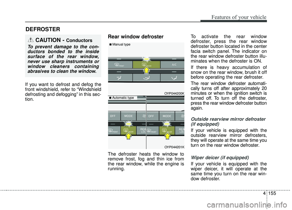
defroster, press the rear window
defroster button located in the center
facia switch panel. The indicator on
the rear window defroster button illu-
minates when the defroster is ON.
If there is heavy accumulation of
snow on the rear window, brush it off
before operating the rear defroster.
The rear window defroster automati-
cally turns off after approximately 20
minutes or when the ignition switch is
turned off. To turn off the defroster,
press the rear window defroster button
again.
Outside rearview mirror defroster
(if equipped)
If your vehicle is equipped with the
outside rearview mirror defrosters,
they will operate at the same time you
turn on the rear window defroster.
Wiper deicer (if equipped)
If your vehicle is equipped with the
wiper deicer, it will operate at the
same time you turn on the rear win-
dow defroster.
DEFROSTER
CAUTION - Conductors
To prevent damage to the con-ductors bonded to the insidesurface of the rear window,never use sharp instruments orwindow cleaners containingabrasives to clean the window.
OYP044200K
OYP044201K
■ Automatic type
■ Manual type
Page 268 of 604
4159
Features of your vehicle
Instrument panel vents
The outlet vents can be opened or
closed separately using the thumb-
wheel (if equipped).
Also, you can adjust the direction of
air delivery from these vents using
the vent control lever as shown.
Temperature control
The temperature control knob allows
you to control the temperature of the
air flowing from the ventilation system.
To change the air temperature in the
passenger compartment, turn the
knob to the right position for warm and
hot air or left position for cooler air.
Air intake control
The air intake control is used to
select the outside (fresh) air position
or recirculated air position.
To change the air intake control posi-
tion, press the control button.
OYP044207K
OYP044206K
OYP044208K
Page 283 of 604
Features of your vehicle
174
4
✽ ✽
NOTICE
Never place anything over the sensor
located on the instrument panel to
ensure better control of the heating
and cooling system.
Manual heating and air condi-
tioning
The heating and cooling system can
be controlled manually by pressing
buttons or turning knob(s) other than
the AUTO button. In this case, the
system works sequentially according
to the order of buttons or knob(s)
selected.
1. Start the engine.
2. Set the mode to the desired posi-
tion.
For improving the effectiveness of
heating and cooling;- Heating:
- Cooling: 3. Set the temperature control to the
desired position.
4. Set the air intake control to the outside (fresh) air position.
5. Set the fan speed control to the desired speed.
6. If air conditioning is desired, turn the air conditioning system on.
Press the AUTO button in order to
convert to full automatic control of
the system.
OYP044223K
Page 285 of 604
Features of your vehicle
176
4
Defrost-Level
Most of the air flow is directed to the
windshield with a small amount of air
directed to the side window defrosters. Instrument panel vents
The outlet vents can be opened or
closed separately using the thumb-
wheel (if equipped).
Also, you can adjust the direction of
air flow from these vents using the
vent control lever as shown.
Temperature control
The temperature will increase to the
maximum (HI) by turning the knob to
the extreme right.
The temperature will decrease to the
minimum (Lo) by turning the knob to
the extreme left.
When turning the knob, the tempera-
ture will increase or decrease by
1°F/0.5°C. When set to the lowest
temperature setting, the air condi-
tioning will operate continuously.
OYP044225K
■Type A■Type B
OYP044206K
OYP044226K
■Driver’s side■Passenger’s side
Page 428 of 604
599
Driving your vehicle
LDW Operation
To activate/deactivate the LDW:
With the ignition switch in the ON
position, press the LDW button locat-
ed on the instrument panel on the
lower left hand side of the driver.
The indicator in the cluster display
will initially illuminate white.
If the indicator (white) was activated
in the previous ignition cycle, the
system turns on automatically.
If you press the LDW button again,
the indicator on the cluster display
will go off.The color of indicator will change
depend on the condition of LDW.
- White : Sensor does not detect the
lane marker or vehicle speed is
less than 64 km/h (40 mph).
- Green : Sensor detects the lane marker.
If the vehicle leaves the lane when the
LDW operates and vehicle speed
exceeds 64 km/h (40 mph), the warn-
ing is issued as follows:
OYP058234N
OYP058235N
OYP058234N
■When the sensor detects the lane line
■When the sensor doesn’t detect the lane line
Page 446 of 604

5117
Driving your vehicle
Following distance
Stay at least twice as far behind the
vehicle ahead as you would when
driving your vehicle without a trailer.
This can help you avoid situations
that require heavy braking and sud-
den turns.
Passing
You’ll need more passing distance
up ahead when you’re towing a trail-
er. And, because of the increased
vehicle length, you’ll need to go
much farther beyond the passed
vehicle before you can return to your
lane. Due to the added load to the
engine when going uphill the vehicle
may also take longer to pass than it
would on flat ground.
Backing up
Hold the bottom of the steering
wheel with one hand. Then, to move
the trailer to the left, just move your
hand to the left. To move the trailer to
the right, move your hand to the
right. Always back up slowly and, if
possible, have someone guide you.
Making turns
When you’re turning with a trailer,
make wider turns than normal. Do
this so your trailer won’t strike soft
shoulders, curbs, road signs, trees,
or other objects near the edge of the
road. Avoid jerky or sudden maneu-
vers. Signal well in advance before
turning or lane changes.
Turn signals when towing a trailer
When you tow a trailer, your vehicle
has to have a different turn signal
flasher and extra wiring. The green
arrows on your instrument panel will
flash whenever you signal a turn or
lane change. Properly connected,
the trailer lights will also flash to alert
other drivers you’re about to turn,
change lanes, or stop.
When towing a trailer, the green
arrows on your instrument panel will
flash for turns even if the bulbs on the
trailer are burned out. Thus, you may
think drivers behind you are seeing
your signals when, in fact, they are
not. It’s important to check occasion-
ally to be sure the trailer bulbs are still
working. You must also check the
lights every time you disconnect and
then reconnect the wires.
Do not connect a trailer lighting sys-
tem directly to your vehicle’s lighting
system. Use only an approved trailer
wiring harness.
An authorized Kia dealer can assist
you in installing the wiring harness.
Page 539 of 604

Maintenance
56
7
3. Pull the suspected fuse straight
out. Use the removal tool provided
on the engine compartment fuse
panel cover.
4. Check the removed fuse; replace it if it is blown.
Spare fuses are provided in theengine compartment fuse panel.
5. Push in a new fuse of the same rating, and make sure it fits tightly
in the clips.
If it fits loosely, consult an authorized
Kia dealer.
If you do not have a spare, use a fuse of the same rating from a circuityou may not need for operating thevehicle, such as the power outletfuse.
If the head lamp, turn signal lamp,
stop signal lamp, fog lamp, DRL, tail
lamp, HMSL do not work and the
fuses are not blown, check the fuse
panel in the engine compartment. If a
fuse is blown, it must be replaced.
✽ ✽ NOTICE
If the headlamp, fog lamp, turn sig-
nal lamp, or tail lamp malfunction
even without any problem to the
lamps, have the vehicle checked by
an authorized Kia dealer for assis-
tance.
Fuse switch
Always set the fuse switch to the ON
position before using the vehicle.
If you move the switch to the OFF
position, some items such as audio
and digital clock must be reset and
transmitter (or smart key) may not
work properly. When the switch is
Off, the caution indicator will be dis-
played on the instrument cluster.
Always place the fuse switch in the
ON position while driving the vehicle.
If the switch is located in the “OFF”
position, a caution indicator will be
displayed in the cluster.
OYP074010K
OYP076011
Page 543 of 604

Maintenance
60
7
Inner fuse panel
Fuse Name Fuse rating Circuit Protected
ECU 10A PCM, Smart Key Control Module/Immobilizer Module
MODULE4 7.5AHead Lamp Leveling Device Actuator LH/RH, Multipurpose Check Connector, Bezel Switch, Electro
Chromic, A/V & Navigation Head Unit, A/C Control Module, Heater Control Module, Passenger
Ventilation Seat Control Module, Driver IMS Control Module, Rear Seat Heater Control Module, Auto
Head Leveling Device Module, ATM Shift Lever ILL.
MODULE3 10A LDWS Module, Stop Lamp, Front Parking Assist Sensor LH/RH, Front Parking Assist Sensor LH/RH
(CENTER), Rear Parking Assist Buzzer, Rear Parking Assist Sensor LH/RH, Rear Parking Assist Sensor
LH/RH (CENTER), Blind Spot Detection Radar LH/RH, FCA(Forward Collision-Avoidance Assist)
MODULE5 7.5A Rear Seat Heater Control Module, AC Inverter Unit, Heater Control Module, Passenger Ventilation Seat
Control Module, Portable Lamp, Around View Unit
MODULE6 7.5A BCM, Smart Key Control Module
WIPER RR 15A Rear Wiper Motor, Wiper RR Relay
CLUSTER 7.5A Instrument Cluster
MODULE8 10A DBL UNIT
A/CON1 7.5A A/C Control Module, Ionizer, Rear A/C Control Switch, PCB Block (Blower Relay, Blower RR Relay)
MEMORY2 10A Data Link Connector, Instrument Cluster, Digital Clock, A/C Control Module, BCM, Power Sliding Door
Module, Driver Door Module, Passenger Safety Power Window Switch, Driver IMS Control Module
SMART KEY3 10A Start/Stop Button Switch, Immobilizer Module
POWER OUTLET2 20A Console Power Outlet A/BAG IND 7.5A Instrument Cluster, Digital Clock, A/C Control Module(Auto)
WASHER 15A Multifunction Switch, BCM
HEATED STEERING 15A Clock Spring (Steering Wheel Switch) MEMORY1 10A Clock Spring (Steering Wheel Switch)
SMART KEY1 25A Smart Key Control Module
POWER OUTLET3 20A Rear Power Outlet MODULE2 7.5A BCM, Driver Door Module, Passenger Door Module