Page 28 of 276

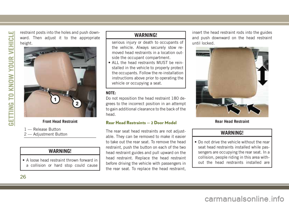
restraint posts into the holes and push down-
ward. Then adjust it to the appropriate
height.
WARNING!
• A loose head restraint thrown forward in
a collision or hard stop could cause
WARNING!
serious injury or death to occupants of
the vehicle. Always securely stow re-
moved head restraints in a location out-
side the occupant compartment.
• ALL the head restraints MUST be rein-
stalled in the vehicle to properly protect
the occupants. Follow the re-installation
instructions above prior to operating the
vehicle or occupying a seat.
NOTE:
Do not reposition the head restraint 180 de-
grees to the incorrect position in an attempt
to gain additional clearance to the back of the
head.
Rear Head Restraints — 2 Door Model
The rear seat head restraints are not adjust-
able. They can be removed to make it easier
to take out the rear seat. To remove the head
restraint, push the button on each of the two
head restraint guides and pull upward on the
head restraint. Replace the head restraint
before driving the vehicle with passengers in
the rear seat. To replace the head restraint,insert the head restraint rods into the guides
and push downward on the head restraint
until locked.WARNING!
• Do not drive the vehicle without the rear
seat head restraints installed while pas-
sengers are occupying the rear seat. In a
collision, people riding in this area with-
out the head restraints installed are
Front Head Restraint
1 — Release Button
2 — Adjustment Button
Rear Head RestraintGETTING TO KNOW YOUR VEHICLE
26
Page 105 of 276

Suitability of Passenger Seats for Universal
Child Restraint System Use
According to the European Directive 2000/3/
EC, the suitability of each passenger seat
position for the installation of Universal Child
Restraint Systems is shown in the following
table:
2 Door Seating Position
Mass GroupUniversal Child Seating
Position Table
Front
PassengerRear Outboard
0-Upto
10 kgXU
0+-Upto
13 kgXU
I-9to18kg X U
II-15to
25 kgXU
III-22to
36 kgXU
4 Door Seating Position
Mass
GroupUniversal Child Seating
Position Table
Front
PassengerRear
OutboardRear
Center
0-Upto
10 kgXUU
0+-Up
to 13 kgXUU
I-9to
18 kgXUU
II-15to
25 kgXUU
III-22to
36 kgXUU
Key of letters used in the table above:
• U = Suitable for “universal” category re-
straints approved for use in this mass
group.
• X = Seat position not suitable for children
in this mass group.
If the head restraint interferes with the instal-
lation of the child restraint system, adjust the
head restraint(if adjustable).
Seat Belts For Older Children
Children over 1.50 m in height can wear seat
belts instead of using child restraints.
Use this simple 5-step test to decide whether
the seat belt properly fits the child or if they
should still use a Group 2 or Group 3 child
restraint to improve the fit of the seat belt:
1. Can the child sit all the way back against
the back of the vehicle seat?
2. Do the child’s knees bend comfortably
over the front of the vehicle seat – while
they are still sitting all the way back?
3. Does the shoulder belt cross the child’s
shoulder between their neck and arm?
4. Is the lap part of the belt as low as
possible, touching the child’s thighs and
not their stomach?
5. Can the child stay seated like this for the
whole trip?
If the answer to any of these questions was
“no,” then the child still needs to use a Group
2 or 3 child restraint in this vehicle. If the
child is using the lap/shoulder belt, check
belt fit periodically and make sure the seat
103
Page 136 of 276

tion for further information. The “Sway Bar
Indicator Light” will flash until the stabilizer/
sway bar has been fully disconnected.
NOTE:
The stabilizer/sway bar may be torque locked
due to left and right suspension height differ-
ences. This condition is due to driving sur-
face differences or vehicle loading. In order
for the stabilizer/sway bar to disconnect/
reconnect, the right and left halves of the bar
must be aligned. This alignment may require
that the vehicle be driven onto level ground or
rocked from side to side.
To return to on-road mode, push the SWAY
BAR switch again.
WARNING!
If the stabilizer/sway bar will not return to
on-road mode, the “Sway Bar Indicator
Light” will flash in the instrument cluster
and vehicle stability is greatly reduced. Do
not attempt to drive the vehicle over
18 mph (29 km/h). Driving faster than
18 mph (29 km/ h) may cause loss of
control of the vehicle, which could result
WARNING!
in serious injury. Contact your local autho-
rized dealer for assistance.
STOP/START SYSTEM —
DIESEL MODELS WITH
MANUAL TRANSMISSION
ONLY
The Stop/Start function is developed to save
fuel and reduce emissions. The system will
stop the engine automatically during a ve-
hicle stop if the required conditions are met.
Pressing the clutch pedal will automatically
restart the vehicle.
Automatic Mode
The Stop/Start feature is en-
abled after every normal cus-
tomer engine start. It will remain
in STOP/START NOT READY un-
til you drive forward with a ve-
hicle speed greater than 3 mph (5 km/h). Atthat time, the system will go into STOP/
START READY and if all other conditions are
met, can go into an STOP/START AUTO STOP
ACTIVE mode.
To Activate The STOP/START AUTO STOP ACTIVE
Mode, The Following Must Occur:
• The system must be in STOP/START
READY state. A STOP/START READY mes-
sage will be displayed in the instrument
cluster. Refer to “Instrument Cluster Dis-
play” in “Getting To Know Your Instrument
Panel” for further information.
• Vehicle speed must be less 3 mph (5 km/h).
• The gear selector must be in the NEUTRAL
position and the clutch pedal must be fully
released
The engine will shut down,the tachometer will
fall to the Stop/Start position,the STOP/START
AUTO STOP ACTIVE message will appear,
and the heater/air conditioning (HVAC) air
flow will be reduced.
STARTING AND OPERATING
134