2020 JEEP WRANGLER wheel
[x] Cancel search: wheelPage 135 of 276

To activate the system, push the bottom of
the AXLE LOCK switch once to lock the rear
axle only (the “Rear Axle Lock Indicator
Light” will illuminate), push the bottom of
the switch again to lock the front axle (the
“Front Axle Lock Indicator Light” will illumi-
nate). When the rear axle is locked, pushing
the bottom of switch again will lock or unlock
the front axle.
NOTE:
The indicator lights will flash until the axles
are fully locked or unlocked.
To unlock the axles, push the top of the AXLE
LOCK switch.
Axle lock will disengage if the vehicle is taken
out of 4L (Low) range, or the ignition switch is
turned to the OFF position.
Electronic Sway Bar Disconnect — If
Equipped
Your vehicle may be equipped with an elec-
tronic disconnecting stabilizer/sway bar. This
system allows greater front suspension travel
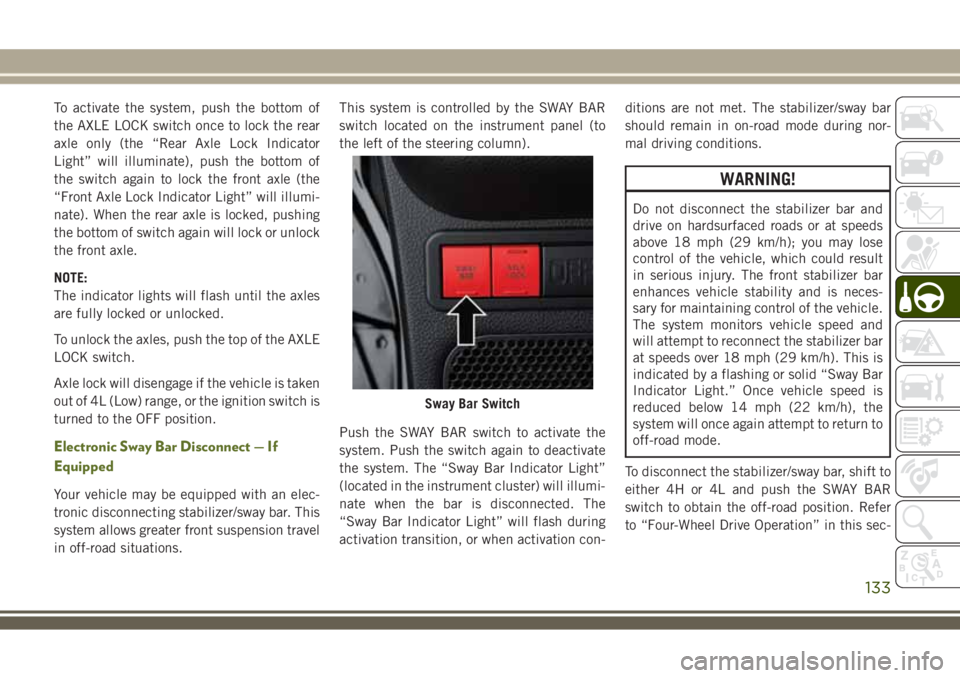
in off-road situations.This system is controlled by the SWAY BAR
switch located on the instrument panel (to
the left of the steering column).
Push the SWAY BAR switch to activate the
system. Push the switch again to deactivate
the system. The “Sway Bar Indicator Light”
(located in the instrument cluster) will illumi-
nate when the bar is disconnected. The
“Sway Bar Indicator Light” will flash during
activation transition, or when activation con-ditions are not met. The stabilizer/sway bar
should remain in on-road mode during nor-
mal driving conditions.
WARNING!
Do not disconnect the stabilizer bar and
drive on hardsurfaced roads or at speeds
above 18 mph (29 km/h); you may lose
control of the vehicle, which could result
in serious injury. The front stabilizer bar
enhances vehicle stability and is neces-
sary for maintaining control of the vehicle.
The system monitors vehicle speed and
will attempt to reconnect the stabilizer bar
at speeds over 18 mph (29 km/h). This is
indicated by a flashing or solid “Sway Bar
Indicator Light.” Once vehicle speed is
reduced below 14 mph (22 km/h), the
system will once again attempt to return to
off-road mode.
To disconnect the stabilizer/sway bar, shift to
either 4H or 4L and push the SWAY BAR
switch to obtain the off-road position. Refer
to “Four-Wheel Drive Operation” in this sec-
Sway Bar Switch
133
Page 138 of 276

To Manually Turn Off The Start Stop System
1. Push the STOP/START Off switch (located
on the switch bank). The light on the
switch will illuminate.
2. The STOP/START OFF message will ap-
pear in the instrument cluster. Refer to
“Instrument Cluster Display” in “Getting
To Know Your Instrument Panel” for fur-
ther information.3. At the next vehicle stop (after turning off
the STOP/START system), the engine will
not be stopped.
4. If the STOP/START system is manually
turned off, the engine can only be started
and stopped by cycling the ignition switch
5. The STOP/START system will reset itself
back to an ON condition every time the
key is turned off and back on.
To Manually Turn On The Start Stop System
1. Push the STOP/START Off switch (located
on the switch bank).
2. The light on the switch will turn off.
System Malfunction
If there is a malfunction in the STOP/START
system, the system will not shut down the
engine. A “SERVICE STOP/START SYSTEM”
message will appear in the instrument cluster
display. Refer to “Warning Lights And Mes-
sages” in “Getting To Know Your Instrument
Panel” for further information.If the “SERVICE STOP/START SYSTEM”
message appears in the instrument cluster
display, have the system checked by your
authorized dealer.
SPEED CONTROL
When engaged, the Speed Control takes over
accelerator operations at speeds greater than
25 mph (40 km/h).
The Speed Control buttons are located on the
right side of the steering wheel.
STOP/START OFF Switch
STARTING AND OPERATING
136
Page 144 of 276

RECREATIONAL TOWING (BEHIND MOTORHOME, ETC.)
Towing This Vehicle Behind Another Vehicle
Towing Condition Wheels OFF the Ground Four-Wheel Drive Models
Flat Tow NONESee Instructions
•
Automatic transmission in PARK.
• Manual transmission in gear
(NOT in NEUTRAL [N]).
• Transfer case in NEUTRAL (N).
• Ignition in ACC position.
• Tow in forward direction.
Dolly TowFront NOT ALLOWED
Rear NOT ALLOWED
On Trailer ALL OK
NOTE:
• When towing your vehicle, always follow applicable state and provincial laws. Contact state and provincial Highway Safety offices for additional
details.
Recreational Towing — Four-Wheel Drive
Models
NOTE:
The transfer case must be shifted into NEU-
TRAL (N), automatic transmission must be in
PARK, and manual transmission must be in
gear (NOT in NEUTRAL) for recreational
towing.
CAUTION!
• DO NOT dolly tow any 4WD vehicle.
Towing with only one set of wheels on
the ground (front or rear) will cause
severe transmission and/or transfer case
damage. Tow with all four wheels either
CAUTION!
ON the ground, or OFF the ground (using
a vehicle trailer).
• Tow only in the forward direction. Towing
this vehicle backwards can cause severe
damage to the transfer case.
STARTING AND OPERATING
142
Page 147 of 276

IN CASE OF EMERGENCY
HAZARD WARNING
FLASHERS................146
BULB REPLACEMENT........146
Replacement Bulbs............146
Bulb Replacement.............147
FUSES...................149
General Information.............150
Totally Integrated Power Module.....150
JACKING AND TIRE
CHANGING................154
Jack/Spare Tire Stowage..........154
Preparations For Jacking.........154
Jacking Instructions............155
Declaration Of Conformance.......157
Jack Usage Precautions..........160
JUMP STARTING............160
Preparations For Jump Start........161
Jump Starting Procedure..........162
IF YOUR ENGINE OVERHEATS . .163GEAR SELECTOR OVERRIDE . . .164
FREEING A STUCK VEHICLE . . .164
TOWING A DISABLED
VEHICLE..................165
Without The Ignition Key..........166
Four–Wheel Drive Models.........166
Tow Eye Usage................167
ENHANCED ACCIDENT RESPONSE
SYSTEM (EARS).............168
EVENT DATA RECORDER
(EDR)....................168
IN CASE OF EMERGENCY
145
Page 156 of 276

JACKING AND TIRE
CHANGING
WARNING!
• Do not attempt to change a tire on the
side of the vehicle close to moving traf-
fic. Pull far enough off the road to avoid
the danger of being hit when operating
the jack or changing the wheel.
• Being under a jacked-up vehicle is dan-
gerous. The vehicle could slip off the
jack and fall on you. You could be
crushed. Never put any part of your body
under a vehicle that is on a jack. If you
need to get under a raised vehicle, take
it to a service center where it can be
raised on a lift.
• Never start or run the engine while the
vehicle is on a jack.
• The jack is designed to be used as a tool
for changing tires only. The jack should
not be used to lift the vehicle for service
purposes. The vehicle should be jacked
on a firm level surface only. Avoid ice or
slippery areas.
Jack/Spare Tire Stowage
The jack and lug wrench are located in the
rear storage compartment.
NOTE:
Turn the black plastic wing nut counterclock-
wise to loosen the jack from the storage bin.Spare Tire Removal
To remove the spare tire from the carrier,
remove the tire cover, if equipped, and re-
move the lug nuts with the lug wrench, turn-
ing them counterclockwise.
NOTE:
If you have added aftermarket accessories to
the spare tire mounted carrier, it cannot ex-
ceed a gross weight of 85 lbs (38.5 kg)
including the weight of the spare tire.
Preparations For Jacking
1. Park on a firm, level surface. Avoid ice or
slippery areas.
WARNING!
Do not attempt to change a tire on the side
of the vehicle close to moving traffic, pull
far enough off the road to avoid being hit
when operating the jack or changing the
wheel.
2. Turn on the Hazard Warning flasher.
3. Apply the parking brake.
Plastic Wing Nut Location
IN CASE OF EMERGENCY
154
Page 157 of 276

4. Shift the automatic transmission into
PARK, or a manual transmission into
REVERSE.
5. Turn the ignition to LOCK.
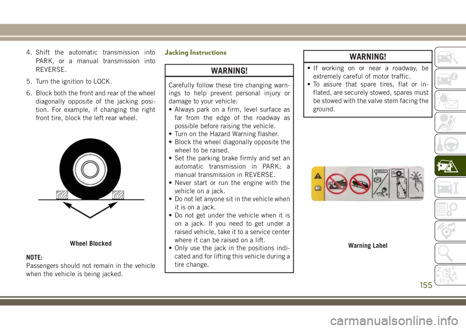
6. Block both the front and rear of the wheel
diagonally opposite of the jacking posi-
tion. For example, if changing the right
front tire, block the left rear wheel.
NOTE:
Passengers should not remain in the vehicle
when the vehicle is being jacked.Jacking Instructions
WARNING!
Carefully follow these tire changing warn-
ings to help prevent personal injury or
damage to your vehicle:
• Always park on a firm, level surface as
far from the edge of the roadway as
possible before raising the vehicle.
• Turn on the Hazard Warning flasher.
• Block the wheel diagonally opposite the
wheel to be raised.
• Set the parking brake firmly and set an
automatic transmission in PARK; a
manual transmission in REVERSE.
• Never start or run the engine with the
vehicle on a jack.
• Do not let anyone sit in the vehicle when
it is on a jack.
• Do not get under the vehicle when it is
on a jack. If you need to get under a
raised vehicle, take it to a service center
where it can be raised on a lift.
• Only use the jack in the positions indi-
cated and for lifting this vehicle during a
tire change.
WARNING!
• If working on or near a roadway, be
extremely careful of motor traffic.
• To assure that spare tires, flat or in-
flated, are securely stowed, spares must
be stowed with the valve stem facing the
ground.
Wheel BlockedWarning Label
155
Page 158 of 276

CAUTION!
Do not attempt to raise the vehicle by
jacking on locations other than those indi-
cated.
1. Remove the spare tire, jack and tools from
the stored location.
2. Loosen (but do not remove) the wheel lug
nuts by turning them to the left one turn
while the wheel is still on the ground.
3. Assemble the jack and jacking tools. Con-
nect the jack handle driver to the exten-
sion, then to the lug wrench.4. Operate the jack from the front or the rear
of the vehicle. Place the jack under the
axle tube, as shown.Do not raise the ve-
hicle until you are sure the jack is fully
engaged.
5. Raise the vehicle by turning the jack
screw clockwise. Raise the vehicle only
until the tire just clears the surface and
enough clearance is obtained to install
the spare tire. Minimum tire lift provides
maximum stability.
WARNING!
Raising the vehicle higher than necessary
can make the vehicle less stable. It could
Front Jack Engagement Location
Rear Jack Engagement Location
IN CASE OF EMERGENCY
156
Page 159 of 276

WARNING!
slip off the jack and hurt someone near it.
Raise the vehicle only enough to remove
the tire.
6. Remove the lug nuts and wheel.
7. Position the spare wheel/tire on the ve-
hicle and install the lug nuts with the
cone-shaped end toward the wheel.
Lightly tighten the lug nuts clockwise.
WARNING!
To avoid the risk of forcing the vehicle off
the jack, do not tighten the wheel nuts
fully until the vehicle has been lowered.
Failure to follow this warning may result in
serious injury.
8. Lower the vehicle by turning the jack
screw to the left, and remove the jack.9. Finish tightening the lug nuts. Push down
on the wrench while tightening for in-
creased leverage. Alternate nuts until
each nut has been tightened twice. Refer
to “Torque Specifications” in “Technical
Specifications” for correct lug nut torque.
10. Remove the jack assembly and wheel
blocks.
11. Secure the tire, jack, and tools in their
proper locations.
WARNING!
A loose tire or jack thrown forward in a
collision or hard stop, could endanger the
occupants of the vehicle. Always stow the
jack parts and the spare tire in the places
provided.
Declaration Of Conformance
1. The undersigned, Tony Fabiano, repre-
senting the manufacturer, herewith de-
clares that the machinery described below
fulfills all relevant provisions of:
• The EC-directive 2006/42/EC on
Machinery
2. Description of machinery.
a) Generic Denomination: Vehicle Jack
b) Function: Lifting Vehicle
d) Ve-
hicle
Modelc) Model
Codef) Work-
ing Loade) Jack
Type
Jeep
®
CompassMK 1200 kg
MaxFGMF1
Jeep
CherokeeKL 1000 kg
MaxFGLF1
Jeep
WranglerJK 1000 kg
MaxFGLF2
Jeep
Grand
CherokeeWK 1700 kg
MaxFGLF3
157