2020 HYUNDAI VELOSTER instrument cluster
[x] Cancel search: instrument clusterPage 16 of 480

I IN
NS
ST
TR
RU
UM
ME
EN
NT
T
P
PA
AN
NE
EL
L
O
OV
VE
ER
RV
VI
IE
EW
W
The actual shape may differ from the illustration.
1-5
Your vehicle at a glance
11. Instrument cluster ....................................3-41
2. Horn ........................................................3-22
3. Driver’s front air bag ................................2-43
4. Key ignition switch/ ....................................5-6
Engine Start/Stop button ..........................5-9
5. Light control/Turn signals ........................3-81
6. Wiper/Washer ..........................................3-92
7. Audio system/Navigation system ..............4-4
8. Hazard warning flasher switch ..................6-2
9. Manual climate control system/ ............3-101
Automatic climate control system ..........3-109
10. Passenger's front air bag ......................2-43
11. Glove box ............................................3-124
12. Power outlet ........................................3-127
13. AUX, USB and iPod
®port........................4-2
14. USB charger ........................................3-128
15.Manual transmission shift lever/ ............5-18
Automatic transmission shift lever/ ........5-22
Dual clutch transmission shift lever ........5-29
16. Drive mode button ................................5-51
17. ESC OFF button ....................................5-45
18. Seat warmer ..........................................2-15
19. Heated steering wheel ..........................3-23
20. Parking Distance Warning (Reverse)
OFF button ............................................3-97
21. Cup holder ..........................................3-126
22. Steering wheel audio controls/ ................4-3
Bluetooth®wireless technology hands-free
controls ....................................................4-4
23. Cruise controls/ ..................................5-100
Smart cruise controls ..........................5-105
[A-D] : Type A ~ Type D
OJS018004C
Page 67 of 480
2-50
Safety system of your vehicle
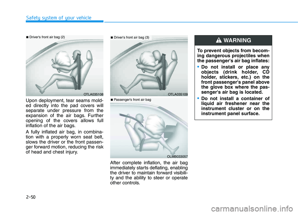
Upon deployment, tear seams mold-
ed directly into the pad covers will
separate under pressure from the
expansion of the air bags. Further
opening of the covers allows full
inflation of the air bags.
A fully inflated air bag, in combina-
tion with a properly worn seat belt,
slows the driver or the front passen-
ger forward motion, reducing the risk
of head and chest injury.
After complete inflation, the air bag
immediately starts deflating, enabling
the driver to maintain forward visibili-
ty and the ability to steer or operate
other controls.
OTLA035108
■Driver's front air bag (2)
To prevent objects from becom-
ing dangerous projectiles when
the passenger's air bag inflates:
Do not install or place any
objects (drink holder, CD
holder, stickers, etc.) on the
front passenger's panel above
the glove box where the pas-
senger's air bag is located.
Do not install a container of
liquid air freshener near the
instrument cluster or on the
instrument panel surface.
WARNING
OTLA035109
■Driver's front air bag (3)
OLMB033057
■Passenger's front air bag
Page 129 of 480
3-129
Convenient features of your vehicle
3
A smart phone or a tablet PC may
get warmer during the re-charging
process. It does not indicate any
malfunction with the charging sys-
tem.
A smart phone or a tablet PC,
which adopts a different re-charg-
ing method, may not be properly
re-charged. In this case, use an
exclusive charger of your device.
The charging terminal is only to
recharge a device. Do not use the
charging terminal either to turn ON
an audio or to play media on the
AVN.Wireless Cellular Phone
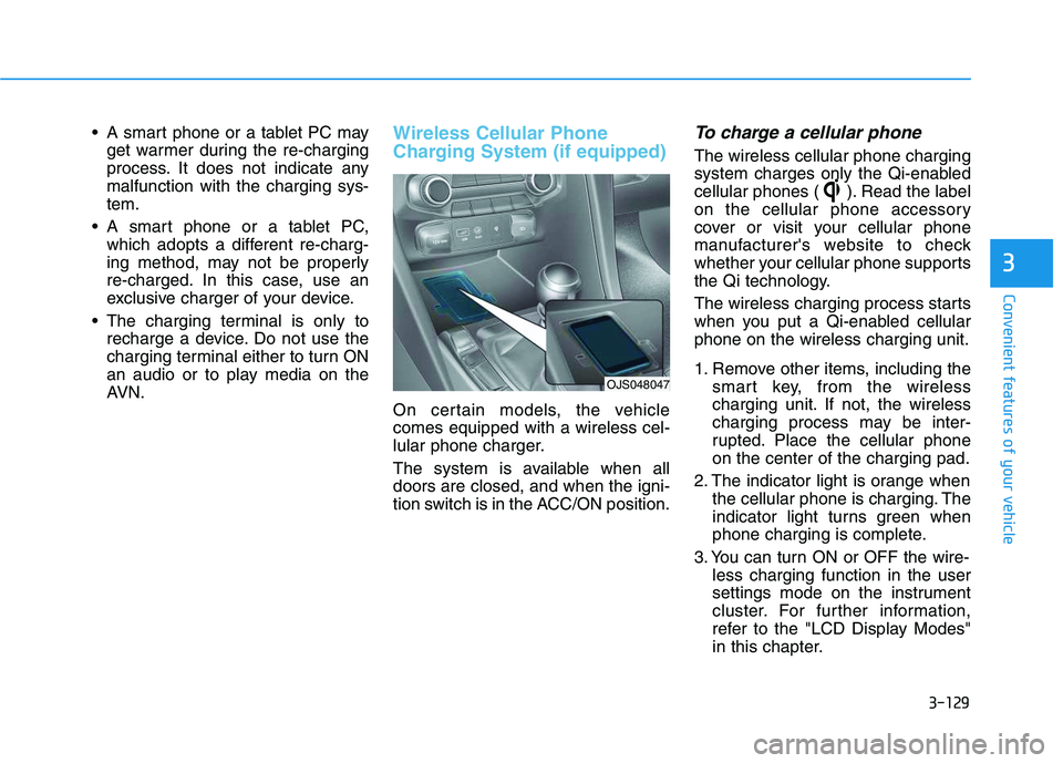
Charging System (if equipped)
On certain models, the vehicle
comes equipped with a wireless cel-
lular phone charger.
The system is available when all
doors are closed, and when the igni-
tion switch is in the ACC/ON position.
To charge a cellular phone
The wireless cellular phone charging
system charges only the Qi-enabled
cellular phones ( ). Read the label
on the cellular phone accessory
cover or visit your cellular phone
manufacturer's website to check
whether your cellular phone supports
the Qi technology.
The wireless charging process starts
when you put a Qi-enabled cellular
phone on the wireless charging unit.
1. Remove other items, including the
smart key, from the wireless
charging unit. If not, the wireless
charging process may be inter-
rupted. Place the cellular phone
on the center of the charging pad.
2. The indicator light is orange when
the cellular phone is charging. The
indicator light turns green when
phone charging is complete.
3. You can turn ON or OFF the wire-
less charging function in the user
settings mode on the instrument
cluster. For further information,
refer to the "LCD Display Modes"
in this chapter.
OJS048047
Page 135 of 480
Convenient features of your vehicle
Accessing Your Vehicle .........................................3-3
Remote Key.........................................................................3-3
Smart Key ............................................................................3-7
Immobilizer System .........................................................3-12
Door Locks ............................................................3-15
Operating Door Locks from Outside the Vehicle ....3-15
Operating Door Locks from Inside the Vehicle .......3-16
Automatic Door Lock and Unlock Features .............3-19
Child-Protector Rear Door Locks ...............................3-19
Theft-Alarm System ............................................3-20
Steering Wheel .....................................................3-21
Electric Power Steering (EPS) .....................................3-21
Tilt Steering / Telescope Steering ..............................3-22
Horn ....................................................................................3-22
Heated Steering Wheel ..................................................3-23
Mirrors ...................................................................3-23
Inside Rearview Mirror ..................................................3-23
Side View Mirrors ...........................................................3-25
Windows ................................................................3-27
Power Windows ...............................................................3-28
Wide Sunroof........................................................3-31
Sunroof opening and closing .......................................3-32
Sliding the sunroof .........................................................3-32
Tilting the sunroof ..........................................................3-32
Sunshade ...........................................................................3-33Resetting the sunroof ....................................................3-33
Sunroof Open Warning ..................................................3-34
Exterior Features .................................................3-35
Hood ...................................................................................3-35
Tailgate...............................................................................3-36
Fuel Filler Door ................................................................3-38
Instrument Cluster ...............................................3-41
Instrument Cluster Control............................................3-42
Gauges and Meters ........................................................3-43
Transmission shift indicator .........................................3-46
Warning and Indicator Lights .......................................3-47
LCD Display Messages ...................................................3-58
LCD Display ...........................................................3-63
LCD Display Control ........................................................3-63
LCD Display Modes .........................................................3-64
Trip Computer .......................................................3-74
Head Up Display (HUD) .......................................3-78
Lighting..................................................................3-81
Exterior Lights .................................................................3-81
Interior Lights...................................................................3-88
Welcome System .............................................................3-90
3
Page 155 of 480
3-21
Convenient features of your vehicle
3
S ST
TE
EE
ER
RI
IN
NG
G
W
WH
HE
EE
EL
L
Electric Power Steering (EPS)
The system assists you with steering
the vehicle. If the vehicle is turned off
or if the power steering system
becomes inoperative, you may still
steer the vehicle, but it will require
increased steering effort.
Should you notice any change in the
effort required to steer during normal
vehicle operation, have the system
checked by an authorized HYUNDAI
dealer.
Information
The following symptoms may occur
during normal vehicle operation:
• The steering effort may be high
immediately after placing the igni-
tion switch in the ON position.
This happens as the system per-
forms the EPS system diagnostics.
When the diagnostics are complet-
ed, the steering wheel effort will
return to its normal condition.
• A click noise may be heard from the
EPS relay after the ignition switch is
in the ON or LOCK/OFF position.• Motor noise may be heard when the
vehicle is at a stop or at a low driv-
ing speed.
• When you operate the steering
wheel in low temperatures, abnor-
mal noise may occur. If the temper-
ature rises, the noise will disappear.
This is a normal condition.
• When an error is detected from the
EPS, the steering effort assist func-
tion will not be activated in order to
help prevent fatal accidents.
Instrument cluster warning lights
may be on or the steering effort may
be high. If these symptoms occur,
drive the vehicle to a safe area as
soon as it is safe to do so. Have the
system checked by an authorized
HYUNDAI dealer as soon as possi-
ble.
i
If the Electric Power Steering
System does not operate nor-
mally, the warning light ( )
will illuminate on the instru-
ment cluster. You may steer
the vehicle, but it will require
increased steering efforts.
Take your vehicle to an
authorized HYUNDAI dealer
and have the system checked
as soon as possible.
When abnormality is detected
in the electric power steering
system, to prevent an acci-
dent, the steering assist func-
tion will stop. At this time, the
warning light turns on or
blinks on the cluster. The
steering wheel may become
difficult to control or operate.
Have your vehicle checked
immediately, after moving the
vehicle to a safe zone.
CAUTION
Page 156 of 480
3-22
Convenient features of your vehicle
Tilt Steering / Telescope
Steering
When adjusting the steering wheel to
a comfortable position, adjust the
steering wheel so that it points
toward your chest, not toward your
face. Make sure you can see the
instrument cluster warning lights and
gauges. After adjusting, push the
steering wheel both up and down to
be certain it is locked in position.
Always adjust the position of the
steering wheel before driving.
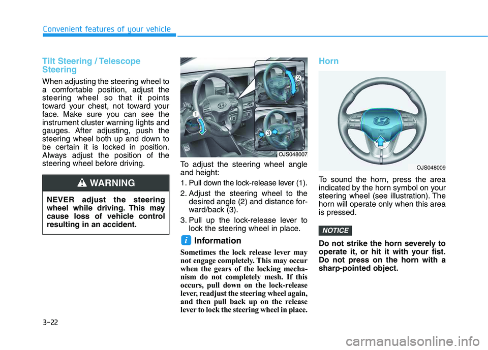
To adjust the steering wheel angle
and height:
1. Pull down the lock-release lever (1).
2. Adjust the steering wheel to the
desired angle (2) and distance for-
ward/back (3).
3. Pull up the lock-release lever to
lock the steering wheel in place.
Information
Sometimes the lock release lever may
not engage completely. This may occur
when the gears of the locking mecha-
nism do not completely mesh. If this
occurs, pull down on the lock-release
lever, readjust the steering wheel again,
and then pull back up on the release
lever to lock the steering wheel in place.
Horn
To sound the horn, press the area
indicated by the horn symbol on your
steering wheel (see illustration). The
horn will operate only when this area
is pressed.
Do not strike the horn severely to
operate it, or hit it with your fist.
Do not press on the horn with a
sharp-pointed object.
NOTICE
i
NEVER adjust the steering
wheel while driving. This may
cause loss of vehicle control
resulting in an accident.
WARNING
OJS048007
OJS048009
Page 176 of 480
3-42
Convenient features of your vehicle
Instrument Cluster Control
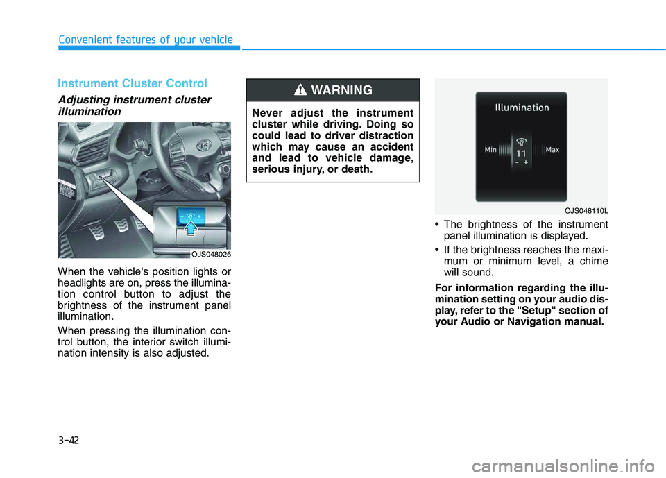
Adjusting instrument cluster
illumination
When the vehicle's position lights or
headlights are on, press the illumina-
tion control button to adjust the
brightness of the instrument panel
illumination.
When pressing the illumination con-
trol button, the interior switch illumi-
nation intensity is also adjusted. The brightness of the instrument
panel illumination is displayed.
If the brightness reaches the maxi-
mum or minimum level, a chime
will sound.
For information regarding the illu-
mination setting on your audio dis-
play, refer to the "Setup" section of
your Audio or Navigation manual. Never adjust the instrument
cluster while driving. Doing so
could lead to driver distraction
which may cause an accident
and lead to vehicle damage,
serious injury, or death.
WARNING
OJS048110L
OJS048026
Page 194 of 480
3-60
Convenient features of your vehicle
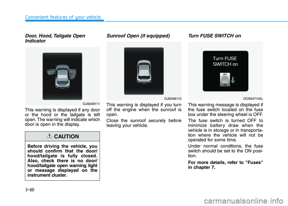
Door, Hood, Tailgate Open
Indicator
This warning is displayed if any door
or the hood or the tailgate is left
open. The warning will indicate which
door is open in the display.
Sunroof Open (if equipped)
This warning is displayed if you turn
off the engine when the sunroof is
open.
Close the sunroof securely before
leaving your vehicle.
Turn FUSE SWITCH on
This warning message is displayed if
the fuse switch located on the fuse
box under the steering wheel is OFF.
The fuse switch is turned OFF to
minimize battery draw when the
vehicle is in storage or in transporta-
tion where the vehicle will not be
operated for some time.
Under normal conditions, the fuse
switch should be set to the ON posi-
tion.
For more details, refer to "Fuses"
in chapter 7. Before driving the vehicle, you
should confirm that the door/
hood/tailgate is fully closed.
Also, check there is no door/
hood/tailgate open warning light
or message displayed on the
instrument cluster.
CAUTION
OJS048111
OJS048112OOS047142L