Page 83 of 480
3-83
Convenient features of your vehicle
3
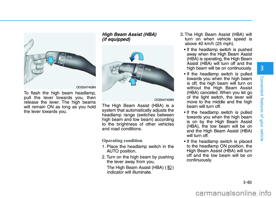
To flash the high beam headlamp,
pull the lever towards you, then
release the lever. The high beams
will remain ON as long as you hold
the lever towards you.
High Beam Assist (HBA)
(if equipped)
The High Beam Assist (HBA) is a
system that automatically adjusts the
headlamp range (switches between
high beam and low beam) according
to the brightness of other vehicles
and road conditions.
Operating condition
1. Place the headlamp switch in the
AUTO position.
2. Turn on the high beam by pushing
the lever away from you.
The High Beam Assist (HBA) ( )
indicator will illuminate.3. The High Beam Assist (HBA) will
turn on when vehicle speed is
above 40 km/h (25 mph).
• If the headlamp switch is pushed
away when the High Beam Assist
(HBA) is operating, the High Beam
Assist (HBA) will turn off and the
high beam will be on continuously.
the headlamp switch is pulled
towards you when the high beam
is off, the high beam will turn on
without the High Beam Assist
(HBA) canceled. When you let go
of the light switch, the lever will
move to the middle and the high
beam will turn off.
the headlamp switch is pulled
towards you when the high beam
is on by the High Beam Assist
(HBA), the low beam will be on
and the High Beam Assist (HBA)
will turn off.
to the headlamp ON position, the
High Beam Assist (HBA) will turn
off and the low beam will be on
continuously.
OOS047408N
OOS047409N
Page 85 of 480
3-85
Convenient features of your vehicle
3
Do not attempt to disassem-
ble the front view camera
without the assistance of an
authorized HYUNDAI dealer
technician. If camera is
removed for any reason, the
system may need to be re-cal-
ibrated. Have the system
inspected by an authorized
HYUNDAI dealer.
If the windshield of your vehi-
cle is replaced, most likely the
front view camera will need to
be re-calibrated. If this
occurs, have your vehicle
inspected and have the sys-
tem re-calibrated by an
authorized HYUNDAI dealer.
Be careful that water doesn’t
get into the High Beam Assist
(HBA) unit and do not remove
or damage related parts of the
High Beam Assist (HBA) sys-
tem.
WARNING When the vehicle is driven on
a narrow curved road or rough
road
When the vehicle is driven on
an uphill road or downhill
road
When only part of the vehicle in
front is visible on a crossroad
or curved road
When there is a traffic light,
reflecting sign, flashing sign or
mirror
When the road conditions are
bad such as being wet or cov-
ered with snow
When a vehicle suddenly
appears from a curve
When the vehicle is tilted from
a flat tire or being towed
When the Lane Keeping Assist
(LKA) system warning light
illuminates
When the light from the on-
coming or front vehicle is not
detected because of exhaust
fume, smoke, fog, snow, etc.
When the front window is cov-
ered with foreign matters such
as ice, dust, fog, or is damaged
3) When the forward visibility is
poor. Such examples may
include:
When the headlamps of an on-
coming vehicle or a vehicle in
front is not detected due to
poor outside visibility (smog,
smoke, dust, fog, heavy rain,
snow, etc.)
When the windshield visibility
is poor
Page 92 of 480
3-92
Convenient features of your vehicle
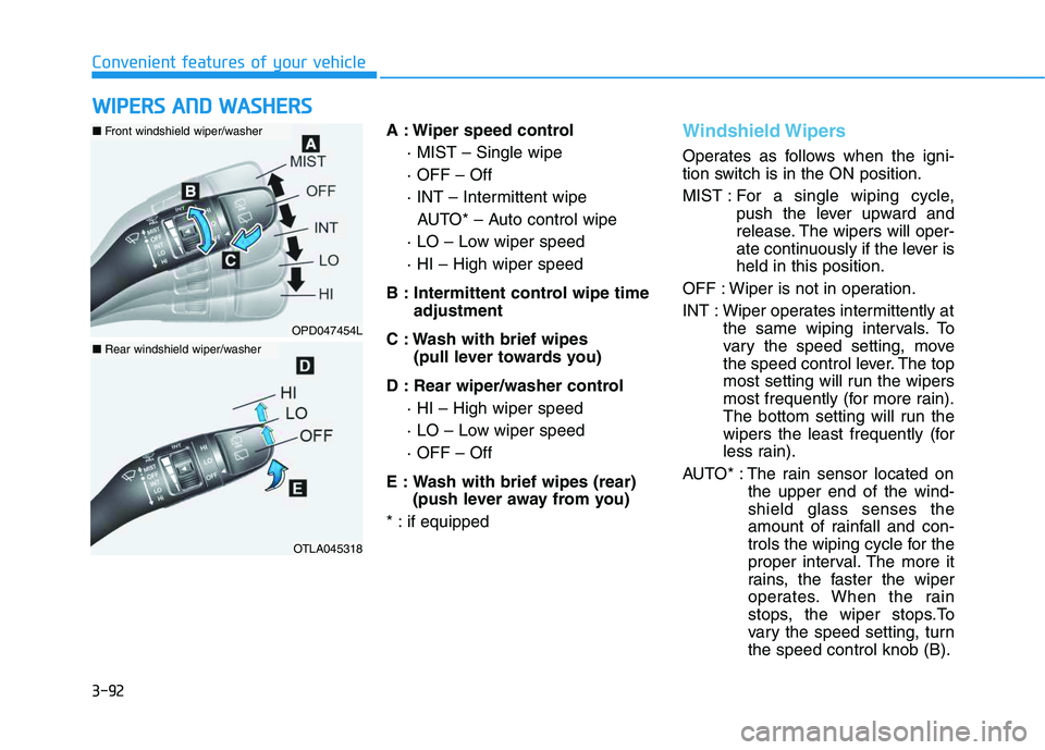
A : Wiper speed control
· MIST – Single wipe
· OFF – Off
· INT – Intermittent wipe
AUTO* – Auto control wipe
· LO – Low wiper speed
· HI – High wiper speed
B : Intermittent control wipe time
adjustment
C : Wash with brief wipes
(pull lever towards you)
D : Rear wiper/washer control
· HI – High wiper speed
· LO – Low wiper speed
· OFF – Off
E : Wash with brief wipes (rear)
(push lever away from you)
* : if equipped
Windshield Wipers
Operates as follows when the igni-
tion switch is in the ON position.
MIST : For a single wiping cycle,
push the lever upward and
release. The wipers will oper-
ate continuously if the lever is
held in this position.
OFF : Wiper is not in operation.
INT : Wiper operates intermittently at
the same wiping intervals. To
vary the speed setting, move
the speed control lever. The top
most setting will run the wipers
most frequently (for more rain).
The bottom setting will run the
wipers the least frequently (for
less rain).
AUTO* : The rain sensor located on
the upper end of the wind-
shield glass senses the
amount of rainfall and con-
trols the wiping cycle for the
proper interval. The more it
rains, the faster the wiper
operates. When the rain
stops, the wiper stops.To
vary the speed setting, turn
the speed control knob (B).
W WI
IP
PE
ER
RS
S
A
AN
ND
D
W
WA
AS
SH
HE
ER
RS
S
OPD047454L
OTLA045318
■Front windshield wiper/washer
■Rear windshield wiper/washer
Page 94 of 480
3-94
Convenient features of your vehicle
Windshield Washers
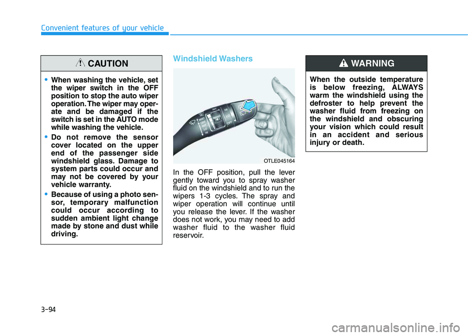
In the OFF position, pull the lever
gently toward you to spray washer
fluid on the windshield and to run the
wipers 1-3 cycles. The spray and
wiper operation will continue until
you release the lever. If the washer
does not work, you may need to add
washer fluid to the washer fluid
reservoir.When the outside temperature
is below freezing, ALWAYS
warm the windshield using the
defroster to help prevent the
washer fluid from freezing on
the windshield and obscuring
your vision which could result
in an accident and serious
injury or death.
WARNING
OTLE045164
When washing the vehicle, set
the wiper switch in the OFF
position to stop the auto wiper
operation. The wiper may oper-
ate and be damaged if the
switch is set in the AUTO mode
while washing the vehicle.
Do not remove the sensor
cover located on the upper
end of the passenger side
windshield glass. Damage to
system parts could occur and
may not be covered by your
vehicle warranty.
Because of using a photo sen-
sor, temporary malfunction
could occur according to
sudden ambient light change
made by stone and dust while
driving.
CAUTION
Page 103 of 480
3-103
Convenient features of your vehicle
3
Face-Level (B, D)
Air flow is directed toward the upper
body and face. Additionally, each
outlet can be controlled to direct the
air discharged from the outlet.
Bi-Level (B, C, D)
Air flow is directed towards the face
and the floor.
Floor-Level (A, C, D)
Most of the air flow is directed to the
floor, with a small amount of the air
being directed to the windshield and
side window defrosters.
Floor & Defrost
(A, C, D)
Most of the air flow is directed to the
floor and the windshield with a small
amount directed to the side window
defrosters.
Defrost-Level (A, D)
Most of the air flow is directed to the
windshield with a small amount of air
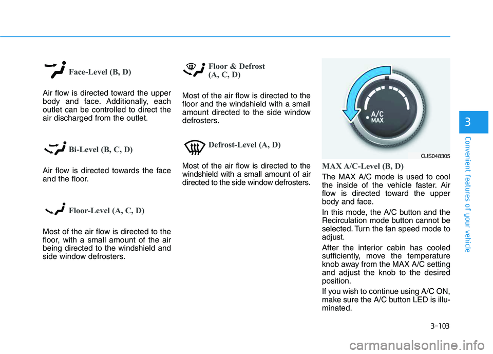
directed to the side window defrosters.MAX A/C-Level (B, D)
The MAX A/C mode is used to cool
the inside of the vehicle faster. Air
flow is directed toward the upper
body and face.
In this mode, the A/C button and the
Recirculation mode button cannot be
selected. Turn the fan speed mode to
adjust.
After the interior cabin has cooled
sufficiently, move the temperature
knob away from the MAX A/C setting
and adjust the knob to the desired
position.
If you wish to continue using A/C ON,
make sure the A/C button LED is illu-
minated.
OJS048305
Page 112 of 480
3-112
Convenient features of your vehicle
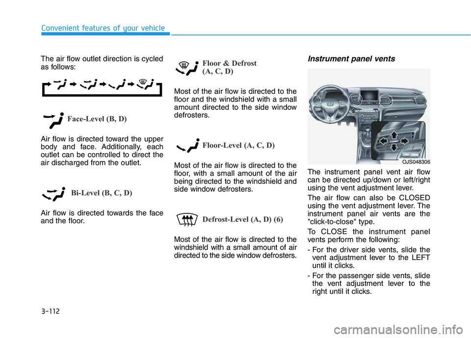
The air flow outlet direction is cycled
as follows:
Face-Level (B, D)
Air flow is directed toward the upper
body and face. Additionally, each
outlet can be controlled to direct the
air discharged from the outlet.
Bi-Level (B, C, D)
Air flow is directed towards the face
and the floor.
Floor & Defrost
(A, C, D)
Most of the air flow is directed to the
floor and the windshield with a small
amount directed to the side window
defrosters.
Floor-Level (A, C, D)
Most of the air flow is directed to the
floor, with a small amount of the air
being directed to the windshield and
side window defrosters.
Defrost-Level (A, D) (6)
Most of the air flow is directed to the
windshield with a small amount of air
directed to the side window defrosters.
Instrument panel vents
The instrument panel vent air flow
can be directed up/down or left/right
using the vent adjustment lever.
The air flow can also be CLOSED
using the vent adjustment lever. The
instrument panel air vents are the
"click-to-close" type.
To CLOSE the instrument panel
vents perform the following:
- For the driver side vents, slide the
vent adjustment lever to the LEFT
until it clicks.
- For the passenger side vents, slide
the vent adjustment lever to the
right until it clicks.
OJS048306
Page 127 of 480
3-127
Convenient features of your vehicle
3
Sunvisor
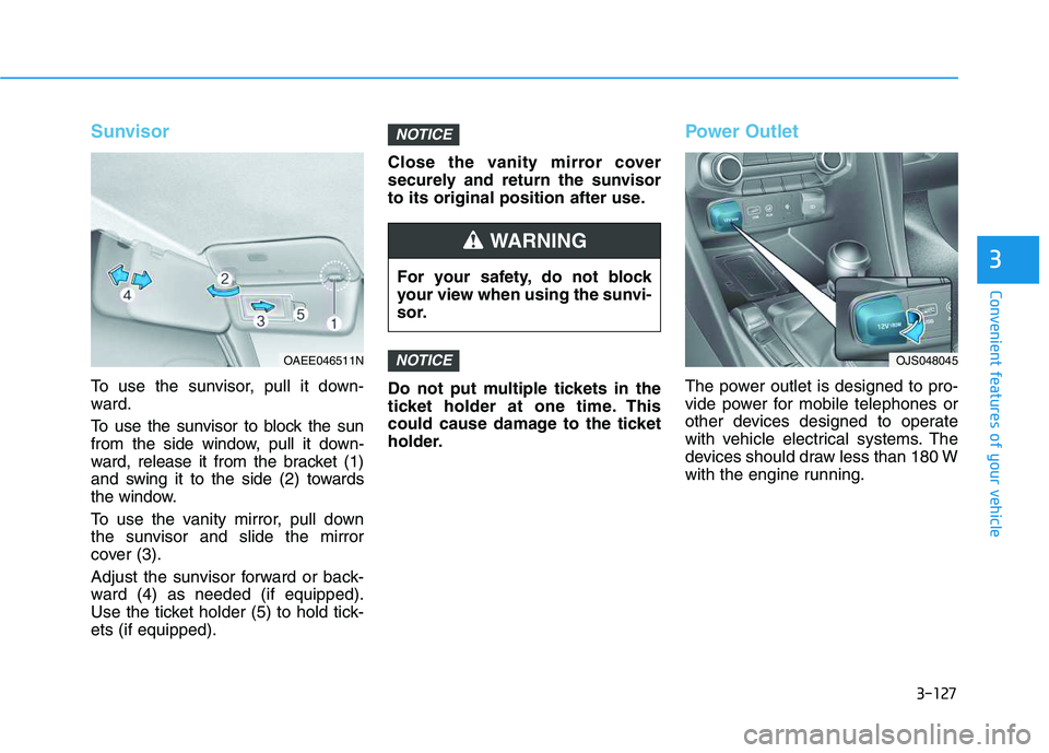
To use the sunvisor, pull it down-
ward.
To use the sunvisor to block the sun
from the side window, pull it down-
ward, release it from the bracket (1)
and swing it to the side (2) towards
the window.
To use the vanity mirror, pull down
the sunvisor and slide the mirror
cover (3).
Adjust the sunvisor forward or back-
ward (4) as needed (if equipped).
Use the ticket holder (5) to hold tick-
ets (if equipped).Close the vanity mirror cover
securely and return the sunvisor
to its original position after use.
Do not put multiple tickets in the
ticket holder at one time. This
could cause damage to the ticket
holder.
Power Outlet
The power outlet is designed to pro-
vide power for mobile telephones or
other devices designed to operate
with vehicle electrical systems. The
devices should draw less than 180 W
with the engine running.
NOTICE
NOTICE
For your safety, do not block
your view when using the sunvi-
sor.
WARNING
OAEE046511NOJS048045
Page 144 of 480
3-10
Mechanical key
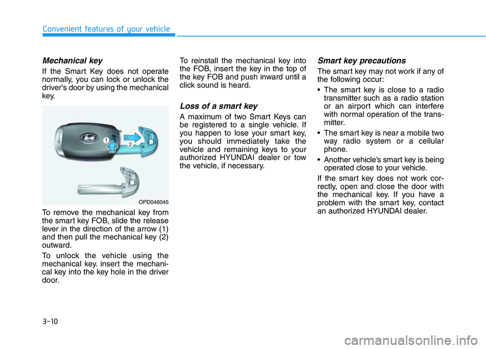
If the Smart Key does not operate
normally, you can lock or unlock the
driver's door by using the mechanical
key.
To remove the mechanical key from
the smart key FOB, slide the release
lever in the direction of the arrow (1)
and then pull the mechanical key (2)
outward.
To unlock the vehicle using the
mechanical key. insert the mechani-
cal key into the key hole in the driver
door.To reinstall the mechanical key into
the FOB, insert the key in the top of
the key FOB and push inward until a
click sound is heard.
Loss of a smart key
A maximum of two Smart Keys can
be registered to a single vehicle. If
you happen to lose your smart key,
you should immediately take the
vehicle and remaining keys to your
authorized HYUNDAI dealer or tow
the vehicle, if necessary.
Smart key precautions
The smart key may not work if any of
the following occur:
The smart key is close to a radio
transmitter such as a radio station
or an airport which can interfere
with normal operation of the trans-
mitter.
The smart key is near a mobile two
way radio system or a cellular
phone.
Another vehicle’s smart key is being
operated close to your vehicle.
If the smart key does not work cor-
rectly, open and close the door with
the mechanical key. If you have a
problem with the smart key, contact
an authorized HYUNDAI dealer.
Convenient features of your vehicle
OPD046045