2020 HYUNDAI TUCSON ULTIMATE cooling
[x] Cancel search: coolingPage 402 of 546
5-136
Driving your vehicle
5. Start the vehicle, apply the brakes,
shift to neutral, release the park-
ing brake and slowly release the
brakes until the trailer chocks
absorb the load.
6. Reapply the brakes and parking
brakes.
7. Move the shift lever to P (Park).
8. Shut off the vehicle and release
the vehicle brakes but leave the
parking brake set.
Driving the vehicle after it has
been parked on a hill
1. With the gear shift lever in P
(Park), apply the brakes and hold
the brake pedal down while per-
forming the following:
and
2. Slowly remove your foot from the
brake pedal.
3. Drive slowly until the trailer is clear
of the chocks.
4. Stop and have someone pick up
and store the chocks.
Maintenance when trailer tow-
ing
Your vehicle will need service more
often when you regularly pull a trail-
er. Important items to pay particular
attention to include engine oil, auto-
matic transmission fluid, axle lubri-
cant and cooling system fluid. Brake
condition is another important item to
frequently check. If you’re trailering,
it’s a good idea to review these items
before you start your trip. Don't forget
to also maintain your trailer and
hitch. Follow the maintenance sched-
ule that accompanied your trailer and
check it periodically. Preferably,
inspect the vehicle and trailer at the
start of each day's driving. Inspect
the hitch mounting to make sure the
hitch is properly secured to the vehi-
cle. Inspect the trailer electrical
wiring to make sure brake lights, turn
signal lights, running lights, and haz-
ard lights are working properly.
Do not get out of the vehicle
without the parking brake
firmly set. If you have left the
engine running, the vehicle
can move suddenly. You and
others could be seriously or
fatally injured.
Do not apply the accelerator
pedal to hold the vehicle on
an uphill.
WARNING
Page 415 of 546
6-6
I IF
F
T
TH
HE
E
E
EN
NG
GI
IN
NE
E
O
OV
VE
ER
RH
HE
EA
AT
TS
S
What to do in an emergency
7. Connect the other end of the sec-
ond jumper cable to the black,
negative (-) chassis ground of
your vehicle (4).
Do not allow the jumper cables to
contact anything except the cor-
rect battery or jumper terminals or
the correct ground. Do not lean
over the battery when making
connections.
8. Start the engine of the assisting
vehicle and let it run at approxi-
mately 2,000 rpm for a few min-
utes. Then start your vehicle.
If your vehicle will not start after a
few attempts, it probably requires
servicing. In this event please seek
qualified assistance. If the cause of
your battery discharging is not
apparent, have your vehicle checked
by an authorized HYUNDAI dealer.Disconnect the jumper cables in the
exact reverse order you connected
them:
1. Disconnect the jumper cable from
the black, negative (-) chassis
ground of your vehicle (4).
2. Disconnect the other end of the
jumper cable from the black, neg-
ative (-) battery/chassis ground of
the assisting vehicle (3).
3. Disconnect the second jumper
cable from the red, positive (+)
battery/jumper terminal of the
assisting vehicle (2).
4. Disconnect the other end of the
jumper cable from the red, positive
(+) jumper terminal of your vehicle
(1).If your temperature gauge indicates
overheating, you experience a loss
of power, or hear loud pinging or
knocking, the engine may be over-
heating. If this happens, you should:
1. Pull off the road and stop as soon
as it is safe to do so.
2. Place the shift lever in P (Park)
and set the parking brake. If the air
conditioning is ON, turn it OFF.
3. If engine coolant is running out
under the vehicle or steam is com-
ing out from the hood, stop the
engine. Do not open the hood until
the coolant has stopped running
or the steaming has stopped. If
there is no visible loss of engine
coolant and no steam, leave the
engine running and check to be
sure the engine cooling fan is
operating. If the fan is not running,
turn the engine off.
Page 416 of 546
6-7
What to do in an emergency
6
4. Check for coolant leaking from the
radiator, hoses or under the vehi-
cle. (If the air conditioning had
been in use, it is normal for cold
water to be draining from it when
you stop.)
5. If engine coolant is leaking out,
stop the engine immediately and
call the nearest authorized
HYUNDAI dealer for assistance.6. If you cannot find the cause of the
overheating, wait until the engine
temperature has returned to nor-
mal. Then, if coolant has been
lost, carefully add coolant to the
reservoir to bring the fluid level in
the reservoir up to the halfway
mark.
7. Proceed with caution, keeping
alert for further signs of overheat-
ing. If overheating happens again,
call an authorized HYUNDAI deal-
er for assistance. While the engine is
running, keep hands,
clothing and tools
away from the mov-
ing parts such as the
cooling fan and drive
belt to prevent seri-
ous injury.
WARNING
Serious loss of coolant indi-
cates a leak in the cooling sys-
tem and should be checked as
soon as possible by an author-
ized HYUNDAI dealer.
CAUTION
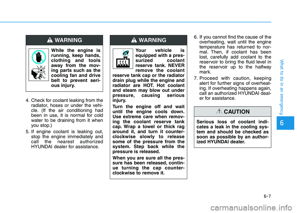
Your vehicle is
equipped with a pres-
surized coolant
reserve tank. NEVER
remove the coolant
reserve tank cap or the radiator
drain plug while the engine and
radiator are HOT. Hot coolant
and steam may blow out under
pressure, causing serious
injury.
Turn the engine off and wait
until the engine cools down.
Use extreme care when remov-
ing the coolant reserve tank
cap. Wrap a towel or thick rag
around it, and turn it counter-
clockwise slowly to release
some of the pressure from the
system. Step back while the
pressure is released.
When you are sure all the pres-
sure has been released, contin-
ue turning the cap counter-
clockwise to remove it.
WARNING
Page 449 of 546

7-15
7
Maintenance
Air Cleaner Filter
A genuine HYUNDAI air cleaner filter
is recommended when the filter is
replaced.
Spark Plugs
Make sure to install new spark plugs
of the correct heat range.
Valve Clearance (if equipped)
Inspect for excessive valve noise
and/or engine vibration and adjust if
necessary. Have an authorized
HYUNDAI dealer perform the opera-
tion.
Cooling System
Check cooling system components,
such as radiator, coolant reservoir,
hoses and connections for leakage
and damage. Replace any damaged
parts.
Engine Coolant
The coolant should be changed at
the intervals specified in the mainte-
nance schedule.
Automatic Transmission Fluid
Automatic transmission fluid should
not be checked under normal usage
conditions. But in severe conditions,
the fluid should be changed at an
authorized HYUNDAI dealer in
accordance to the scheduled mainte-
nance at the beginning of this chap-
ter.
Information
Automatic transmission fluid color is
basically red.
As the vehicle is driven, the automatic
transmission fluid will begin to look
darker. This is a normal condition and
you should not judge the need to
replace the fluid based upon the
changed color.
The use of a non-specified fluid
could result in transmission mal-
function and failure. Use only the
specified automatic transmission
fluid (refer to "Recommended
Lubricants and Capacities" in
chapter 8).
Brake Hoses and Lines
Visually check for proper installation,
chafing, cracks, deterioration and
any leakage. Replace any deteriorat-
ed or damaged parts immediately.
Brake Fluid
Check brake fluid level in the brake
fluid reservoir. The level should be
between the MIN and the MAX
marks on the side of the reservoir.
Use only hydraulic brake fluid con-
forming to DOT 3 or DOT 4 specifi-
cation.
NOTICE
i
Page 453 of 546
7-19
7
Maintenance
E EN
NG
GI
IN
NE
E
C
CO
OO
OL
LA
AN
NT
T
The high-pressure cooling system
has a reservoir filled with year-round
antifreeze coolant. The reservoir is
filled at the factory.
Check the antifreeze protection and
coolant level at least once a year, at
the beginning of the winter season
and before traveling to a colder cli-
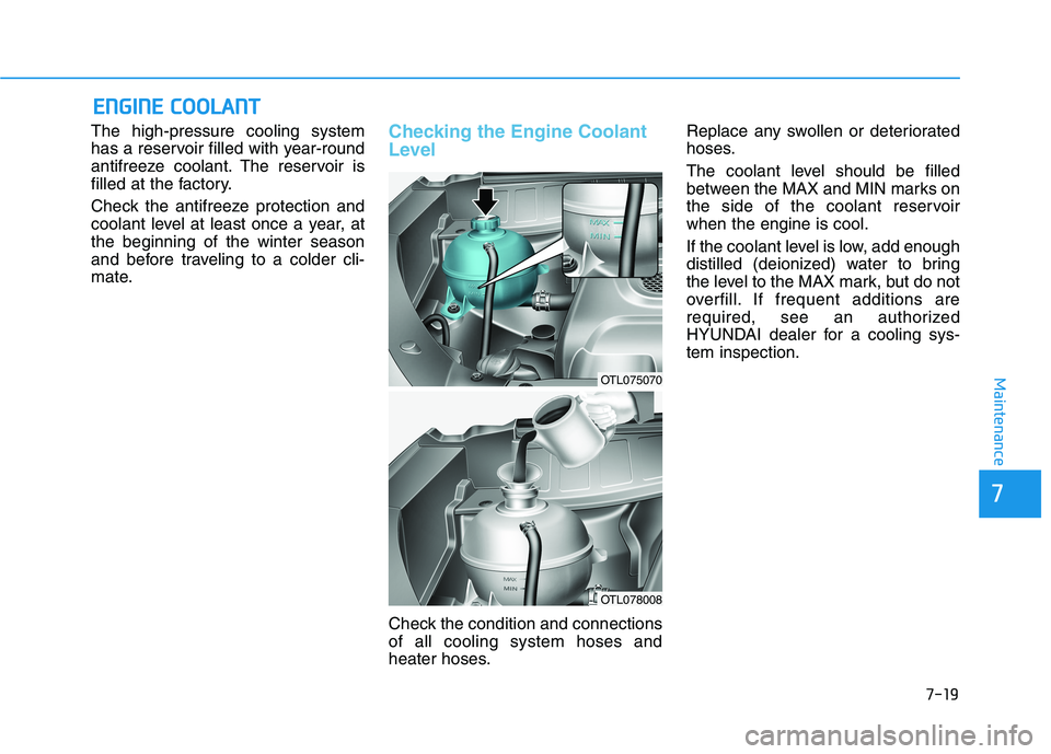
mate.Checking the Engine Coolant
Level
Check the condition and connections
of all cooling system hoses and
heater hoses.Replace any swollen or deteriorated
hoses.
The coolant level should be filled
between the MAX and MIN marks on
the side of the coolant reservoir
when the engine is cool.
If the coolant level is low, add enough
distilled (deionized) water to bring
the level to the MAX mark, but do not
overfill. If frequent additions are
required, see an authorized
HYUNDAI dealer for a cooling sys-
tem inspection.
OTL075070
OTL078008
Page 454 of 546
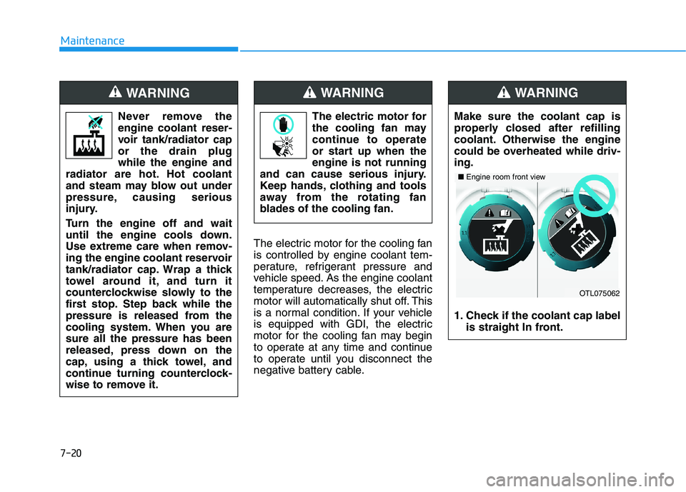
7-20
Maintenance
The electric motor for the cooling fan
is controlled by engine coolant tem-
perature, refrigerant pressure and
vehicle speed. As the engine coolant
temperature decreases, the electric
motor will automatically shut off. This
is a normal condition. If your vehicle
is equipped with GDI, the electric
motor for the cooling fan may begin
to operate at any time and continue
to operate until you disconnect the
negative battery cable. Never remove the
engine coolant reser-
voir tank/radiator cap
or the drain plug
while the engine and
radiator are hot. Hot coolant
and steam may blow out under
pressure, causing serious
injury.
Turn the engine off and wait
until the engine cools down.
Use extreme care when remov-
ing the engine coolant reservoir
tank/radiator cap. Wrap a thick
towel around it, and turn it
counterclockwise slowly to the
first stop. Step back while the
pressure is released from the
cooling system. When you are
sure all the pressure has been
released, press down on the
cap, using a thick towel, and
continue turning counterclock-
wise to remove it.
WARNING
The electric motor for
the cooling fan may
continue to operate
or start up when the
engine is not running
and can cause serious injury.
Keep hands, clothing and tools
away from the rotating fan
blades of the cooling fan.
WARNING
Make sure the coolant cap is
properly closed after refilling
coolant. Otherwise the engine
could be overheated while driv-
ing.
1. Check if the coolant cap label
is straight In front.
WARNING
OTL075062
■Engine room front view
Page 495 of 546

7
Maintenance
Engine compartment main fuse panel
Fuse NameFuse rating Circuit Protected
MULTI
FUSE-1
MDPS 80AMDPS Unit
B+1 60ASmart Junction Block (ARISU-LT IPS 1, IPS 2, IPS 3, IPS 4, Fuse - AMP)
B+2 60ASmart Junction Block (ARISU-LT IPS 5, IPS 6, IPS 7, IPS 8, Fuse - SMART KEY1,
SMART KEY2, BRAKE SWITCH, MODULE9)
B+3 50ASmart Junction Block (Fuse - SUNROOF1, SUNROOF2, S/HEATER FRT, S/HEATER RR,
SAFETY P/WINDOW DRV),
Power Window Relay (Fuse - P/WINDOW LH, P/WINDOW RH)
ABS1 40AESC Module, Multipurpose Check Connector
ABS2 40AESC Module, Multipurpose Check Connector
IG1 40AIgnition Switch (W/O Smart Key),
PCB Block (PDM (IG1)/PDM (ACC) Relay - With Smart Key)
IG2 30AStart Relay, Ignition Switch (W/O Smart Key),
PCB Block (PDM (IG2) Relay - With Smart Key)
MULTI
FUSE-2PTC HEATER 150APTC 1 Relay
PTC HEATER 250APTC 2 Relay
FUSE
B+450A Smart Junction Block (Fuse - MODULE8, 4WD, P/SEAT (DRV), P/SEAT (PASS),
TAILGATE OPEN, DOOR LOCK,
Leak Current Autocut Device - Fuse Switch, INTERIOR LAMP, MULTIMEDIA, MEMORY2)
COOLING FAN140A [G4NC/G4KJ] Cooling Fan High Relay
50A [G4FJ] Cooling Fan High Relay
TCU340A [G4FJ - 7DCT] TCM
TCU440A [G4FJ - 7DCT] TCM
BLOWER40A Blower Relay
POWER TAILGATE40A Power Tail Gate Module
REAR HEATED40A Rear Defogger Relay
7-61
Page 496 of 546
![HYUNDAI TUCSON ULTIMATE 2020 Owners Manual 7-62
Maintenance
Engine compartment main fuse panel
Fuse Name Fuse ratingCircuit Protected
WIPER FRT210A BCW
E-CVVT220A [G4KJ] PCM
E-CVVT120A [G4KJ] PCM
WIPER FRT125A Ignition Switch (W/O Smart Key), HYUNDAI TUCSON ULTIMATE 2020 Owners Manual 7-62
Maintenance
Engine compartment main fuse panel
Fuse Name Fuse ratingCircuit Protected
WIPER FRT210A BCW
E-CVVT220A [G4KJ] PCM
E-CVVT120A [G4KJ] PCM
WIPER FRT125A Ignition Switch (W/O Smart Key),](/manual-img/35/56196/w960_56196-495.png)
7-62
Maintenance
Engine compartment main fuse panel
Fuse Name Fuse ratingCircuit Protected
WIPER FRT210A BCW
E-CVVT220A [G4KJ] PCM
E-CVVT120A [G4KJ] PCM
WIPER FRT125A Ignition Switch (W/O Smart Key), PDM (IG2) Relay (With Smart Key)
TCU115A [G4FJ] TCM (7DCT), [G4KJ] PCM
A/C10A E/R Junction Block (A/C Relay)
ECU320A PCM (G4NC/G4KJ) / ECM (G4FJ)
HORN15A Horn Relay
BATTERY
MANAGEMENT10A Not Used
SENSOR210A
[G4NC] Oil Control Valve #1/#2, Camshaft Position Sensor #1/#2, Purge Control Solenoid Valve,
Variable Intake Solenoid Valve, Canister Close Valve, E/R Junction Block (A/C Relay,
Cooling Fan High Relay)
[G4FJ] Oil Control Valve #1/#2, Purge Control Solenoid Valve, Canister Close Valve,
RCV Control Solenoid Valve, E/R Junction Block (A/C Relay, Cooling Fan High Relay)
[G4KJ] Canister Close Valve, Variable Intake Solenoid Valve,
E/R Junction Block (A/C Relay, Cooling Fan High Relay)
SENSOR115A Oxygen Sensor (Up)/(Down)
ECU220A IGNITION COIL #1/#2/#3/#4, Condenser (G4NC)
ECU515A PCM (G4NC) / ECM (G4FJ)
ECU415A PCM (G4NC/G4KJ) / ECM (G4FJ)
SENSOR310A[G4NC] PCM
[G4FJ] ECM
[G4KJ] Purge Control Solenoid Valve, Oil Control Valve