Page 458 of 561

7-33
7
Maintenance
Wheel Alignment and Tire
Balance
The wheels on your vehicle were
aligned and balanced carefully at the
factory to give you the longest tire life
and best overall performance.
In most cases, you will not need to
have your wheels aligned again.
However, if you notice unusual tire
wear or your vehicle pulling one way
or the other, the alignment may need
to be reset.
If you notice your vehicle vibrating
when driving on a smooth road, your
wheels may need to be rebalanced.
Improper wheel weights can dam-
age your vehicle's aluminum
wheels. Use only approved wheel
weights.
Tire Replacement
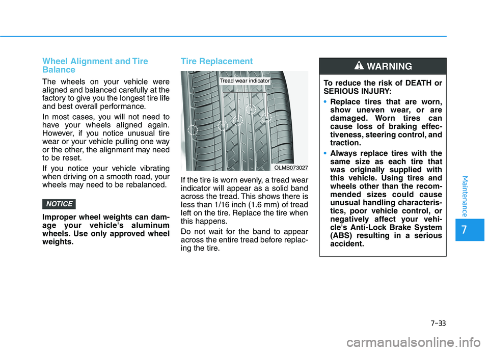
If the tire is worn evenly, a tread wear
indicator will appear as a solid band
across the tread. This shows there is
less than 1/16 inch (1.6 mm) of tread
left on the tire. Replace the tire when
this happens.
Do not wait for the band to appear
across the entire tread before replac-
ing the tire.
NOTICE
OLMB073027
Tread wear indicatorTo reduce the risk of DEATH or
SERIOUS INJURY:
Replace tires that are worn,
show uneven wear, or are
damaged. Worn tires can
cause loss of braking effec-
tiveness, steering control, and
traction.
Always replace tires with the
same size as each tire that
was originally supplied with
this vehicle. Using tires and
wheels other than the recom-
mended sizes could cause
unusual handling characteris-
tics, poor vehicle control, or
negatively affect your vehi-
cle's Anti-Lock Brake System
(ABS) resulting in a serious
accident.
WARNING
Page 475 of 561

7-50
Maintenance
Fuse NameFuse RatingProtected Component
MEMORY110APower Tail Gate Module, A/C Control Module, A/C Control Panel
MODULE110AICM Relay Box (Outside Mirror Folding/Unfolding Relay), A/V & Navigation Head Unit (Hazard Lamp Switch),
Shift Selection Switch (SBW), Auto Light & Photo Sensor, Driver/Passenger Power Outside Mirror,
Instrument Cluster
TAIL GATEOPEN10ATail Gate Relay
P/WINDOW RH25APower Window RH Relay
P/WINDOW LH25APower Window LH Relay, Driver Safety Window Module
P/SEAT DRV25ADriver Seat Manual Switch
MODULE47.5AIBU, Remote Control Smart Parking Assist Unit, VESS Unit, Electronic Parking Brake Switch,
Lane Keeping Assist Unit(Line), Blind-Spot Collision Warning Unit LH/RH, Crash Pad Switch,
PE Room Junction Block (Multipurpose Check Connector)
MODULE87.5AData Link Connector, Crash Pad Switch, Electro Chromic Mirror
S/HEATER RR20ARear Seat Heater
HEATED
MIRROR10ADriver/Passenger Power Outside Mirror, A/C Control Panel
S/HEATER FRT20AFront Air Ventilation/Seat Heater Seat Control Module
Instrument panel fuse panel
Page 476 of 561
7-51
7
Maintenance
Fuse NameFuse RatingProtected Component
AMP25AAMP
MULTI MEDIA15AA/V & Navigation Head Unit, Center Fascia Switch Panel
MODULE510AFront Air Ventilation/Seat Heater Seat Control Module, AMP, A/V & Navigation Head Unit,
A/C Control Panel, PTC Heater, A/C Control Module, Electro Chromic Mirror, Rear Seat Heater
WIPER (RR)15AICM Relay Box (Rear Wiper Relay), Rear Wiper Motor
DOOR LOCK20ADoor Lock Relay, Door Unlock Relay, ICM Relay Box (Two Turn Door Unlock Relay)
IBU115AIBU
BRAKE
SWITCH10AIBU, Stop Lamp Switch
P/SEAT PASS25APassenger Seat Manual Switch
A/C7.5AA/C Control Module, Incar Temperature Sensor, A/C Control Panel,
Cluster Ionizer, A/C Compressor, PE Room Junction Block (Blower Relay)
AIR BAG210ASRS Control Module
WASHER15AMultifunction Switch
Instrument panel fuse panel
Page 479 of 561
7-54
Maintenance
Motor compartment fuse panel
TypeFuse NameFuse RatingCircuit Protected
MULTI FUSE-1
B+260AICU Junction Block (IPS Control Module, IPS1)
B+360AICU Junction Block (IPS Control Module)
COOLING PE PUMP40APE Room Coolant Pump (CPP)
EPB240AElectronic Brake Control Module
IG240APE Room Junction Block (IG2 Relay)
EPB140AElectronic Brake Control Module, PE Room Junction Block (Multipurpose Check Connector)
B+460AICU Junction Block (Fuse - SUNROOF1, SUNROOF2, AMP, P/SEAT DRV,
P/SEAT PASS, S/HEATER FRT, P/WINDOW LH, P/WINDOW RH, TAIL GATE OPEN)
IMEB80AElectronic Brake Control Module
MULTI FUSE-2
BLOWER50APE Room Junction Block (Blower Relay)
MDPS80AMDPS Unit
Page 480 of 561
7-55
7
Maintenance
Motor compartment fuse panel
TypeFuse NameFuse RatingCircuit Protected
FUSE
HVJB LV15AHV Junction Block
RCU15ADriver / Passenger Auto Flush Door Handle Module,
Rear Auto Flush Door Handle Module LH/RH
FUEL DOOROPEN7.5AICM Relay Box (Fuel Filler Door Relay)
E-SHIFTER40APE Room Junction Block (E-Shifter Relay)
INVERTER30AAC Inverter
REAR
HEATED40APE Room Junction Block (Rear Heated Relay)
B+150AICU Junction Block ((Fuse - MODULE1, AIR BAG2, MODULE8,
S/HEATER RR, DOOR LOCK, IBU1, BRAKE SWITCH), Leak Current Autocut Relay)
POWER
TAIL GATE30APower Tail Gate Module
WIPER FRT30AFront Wiper Motor
COOLING
STACK PUMP10AStack Coolant Pump (CSP)
INVERTER LV7.5AInverter
Page 481 of 561
7-56
Maintenance
TypeFuse NameFuse RatingCircuit Protected
FUSE
BHDC7.5AIDC
HMU110AHMU
BATTERY
MANAGEMENT10ABMS Control Module
FUEL CELL
CONTROL UNIT15AFCU
BMS FAN15APE Room Junction Block (BMS FAN Relay)
Motor compartment fuse panel
Page 510 of 561

H5
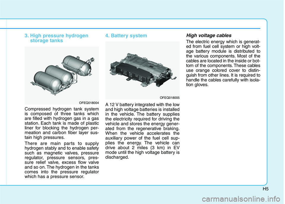
3. High pressure hydrogen
storage tanks
Compressed hydrogen tank system
is composed of three tanks which
are filled with hydrogen gas in a gas
station. Each tank is made of plastic
liner for blocking the hydrogen per-
meation and carbon fiber layer sus-
tain high pressures.
There are main parts to supply
hydrogen stably and to enable safety
such as magnetic valves, pressure
regulator, pressure sensors, pres-
sure relief valve, excess flow valve
and so on. The hydrogen in the tanks
comes into the pressure regulator
which has a pressure sensor.
4. Battery system
A 12 V battery integrated with the low
and high voltage batteries is installed
in the vehicle. The battery supplies
the electricity required for driving the
vehicle and stores the energy gener-
ated from the regenerative braking.
When the vehicle accelerates the
auxiliary power of the fuel cell sup-
plies the energy. The vehicle can
drive about 2 miles (3 km) in EV
mode until the high voltage battery is
discharged.
High voltage cables
The electric energy which is generat-
ed from fuel cell system or high volt-
age battery module is distributed to
the various components. Most of the
cables are located in the inside or bot-
tom of the components. These cables
use orange colored cover to distin-
guish from other lines. It is required to
handle the cables carefully with isola-
tion gloves.
OFEQ018004
OFEQ018005
Page 514 of 561

H9
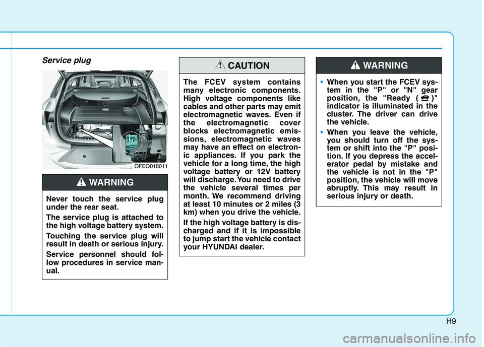
Service plug
OFEQ018011
The FCEV system contains
many electronic components.
High voltage components like
cables and other parts may emit
electromagnetic waves. Even if
the electromagnetic cover
blocks electromagnetic emis-
sions, electromagnetic waves
may have an effect on electron-
ic appliances. If you park the
vehicle for a long time, the high
voltage battery or 12V battery
will discharge. You need to drive
the vehicle several times per
month. We recommend driving
at least 10 minutes or 2 miles (3
km) when you drive the vehicle.
If the high voltage battery is dis-
charged and if it is impossible
to jump start the vehicle contact
your HYUNDAI dealer.
CAUTION
When you start the FCEV sys-
tem in the "P" or "N" gear
position, the "Ready ( )"
indicator is illuminated in the
cluster. The driver can drive
the vehicle.
When you leave the vehicle,
you should turn off the sys-
tem or shift into the "P" posi-
tion. If you depress the accel-
erator pedal by mistake and
the vehicle is not in the "P"
position, the vehicle will move
abruptly. This may result in
serious injury or death.
WARNING
Never touch the service plug
under the rear seat.
The service plug is attached to
the high voltage battery system.
Touching the service plug will
result in death or serious injury.
Service personnel should fol-
low procedures in service man-
ual.
WARNING