2020 HYUNDAI NEXO display
[x] Cancel search: displayPage 399 of 561

What to do in an emergency
6
Hazard Warning Flasher .......................................6-2
In Case of an Emergency While Driving.............6-2
If an accident occurs........................................................6-2
If a fire occurs ...................................................................6-3
Emergency venting of hydrogen gas...........................6-3
If a submersion in water occurs....................................6-3
If the vehicle stalls at a crossroad or crossing .........6-3
If you have a flat tire while driving..............................6-4
If the vehicle stalls while driving...................................6-4
If the Vehicle Will Not Start .................................6-4
If the 12 Volt Battery is Discharged ...................6-5
Before Jump Starting .......................................................6-5
Jump Starting......................................................................6-6
If the Vehicle Overheats .......................................6-9
Tire Pressure Monitoring System (TPMS).......6-11
Check Tire Pressure .......................................................6-11
Tire Pressure Monitoring System ...............................6-12
Low Tire Pressure Telltale ............................................6-13
Low Tire Pressure LCD Display with Position
Indicator.............................................................................6-13
TPMS Malfunction Indicator ........................................6-14
Changing a Tire with TPMS..........................................6-15
If You Have a Flat Tire
(With Tire Mobility Kit) .......................................6-17
Towing ...................................................................6-24
Towing Service .................................................................6-24
Removable Towing Hook ...............................................6-25
Emergency Towing..........................................................6-26
Page 409 of 561
6-11
What to do in an emergency
6
T TI
IR
RE
E
P
PR
RE
ES
SS
SU
UR
RE
E
M
MO
ON
NI
IT
TO
OR
RI
IN
NG
G
S
SY
YS
ST
TE
EM
M
(
(T
TP
PM
MS
S)
)
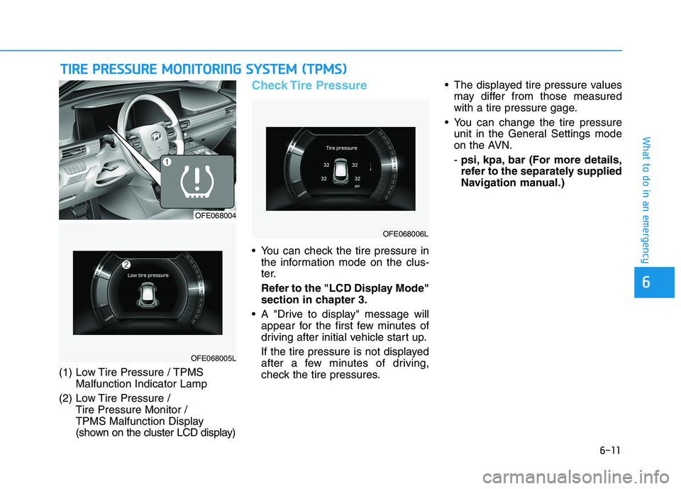
(1) Low Tire Pressure / TPMS
Malfunction Indicator Lamp
(2) Low Tire Pressure /
Tire Pressure Monitor /
TPMS Malfunction Display
(shown on the cluster LCD display)
Check Tire Pressure
You can check the tire pressure in
the information mode on the clus-
ter.
Refer to the "LCD Display Mode"
section in chapter 3.
A "Drive to display" message will
appear for the first few minutes of
driving after initial vehicle start up.
If the tire pressure is not displayed
after a few minutes of driving,
check the tire pressures. The displayed tire pressure values
may differ from those measured
with a tire pressure gage.
You can change the tire pressure
unit in the General Settings mode
on the AVN.
- psi, kpa, bar (For more details,
refer to the separately supplied
Navigation manual.)
OFE068005L
OFE068004
OFE068006L
Page 411 of 561
6-13
What to do in an emergency
6
If any of the below happens, have
the system checked by an author-
ized HYUNDAI dealer.
1. The Low Tire Pressure TPMS
Malfunction Indicator does not
illuminate for 3 seconds when
the POWER button is placed to
the ON position or vehicle is ON
( indicator ON).
2. The TPMS Malfunction Indicator
remains illuminated after blink-
ing for approximately 1 minute.
3. The Low Tire Pressure LCD dis-
play remains illuminated
Low Tire Pressure
Telltale
Low Tire Pressure
LCD Display with
Position Indicator
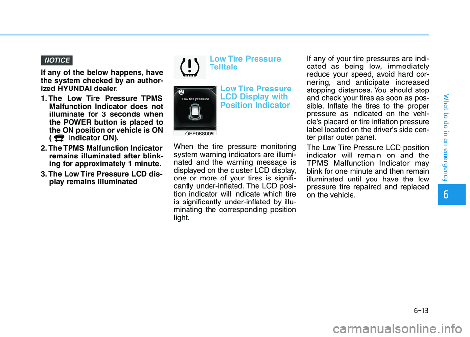
When the tire pressure monitoring
system warning indicators are illumi-
nated and the warning message is
displayed on the cluster LCD display,
one or more of your tires is signifi-
cantly under-inflated. The LCD posi-
tion indicator will indicate which tire
is significantly under-inflated by illu-
minating the corresponding position
light.If any of your tire pressures are indi-
cated as being low, immediately
reduce your speed, avoid hard cor-
nering, and anticipate increased
stopping distances. You should stop
and check your tires as soon as pos-
sible. Inflate the tires to the proper
pressure as indicated on the vehi-
cle’s placard or tire inflation pressure
label located on the driver's side cen-
ter pillar outer panel.
The Low Tire Pressure LCD position
indicator will remain on and the
TPMS Malfunction Indicator may
blink for one minute and then remain
illuminated until you have the low
pressure tire repaired and replaced
on the vehicle.
NOTICE
OFE068005L
Page 412 of 561
6-14
What to do in an emergency
TPMS Malfunction
Indicator
The TPMS Malfunction Indicator will
illuminate after it blinks for approxi-
mately one minute when there is a
problem with the Tire Pressure
Monitoring System.
Have the system checked by an
authorized HYUNDAI dealer as soon
as possible.
If there is a malfunction with the
TPMS, the individual tire pres-
sures in the cluster LCD display
will not be available. Have the sys-
tem checked by an authorized
HYUNDAI dealer as soon as possi-
ble.
NOTICE
In winter or cold weather, the
Low Tire Pressure Telltale may
be illuminated if the tire pres-
sure was adjusted to the recom-
mended tire inflation pressure
in warm weather. It does not
mean your TPMS is malfunc-
tioning because the decreased
temperature leads to a propor-
tional lowering of tire pressure.
When you drive your vehicle
from a warm area to a cold area
or from a cold area to a warm
area, or the outside temperature
is greatly higher or lower, you
should check the tire inflation
pressure and adjust the tires to
the recommended tire inflation
pressure.
CAUTION
Low pressure damage
Significantly low tire pressure
makes the vehicle unstable and
can contribute to loss of vehicle
control and increased braking
distances.
Continued driving on low pres-
sure tires can cause the tires to
overheat and fail.
WARNING
Page 417 of 561
6-19
What to do in an emergency
6
Do not use the Tire Mobility Kit if
the ambient temperature is below
-22°F (-30°C).
In case of skin contact with the-
sealant, wash the area thoroughly-
with plenty of water. If the irritation-
persists, seek medical attention.
In case of eye contact with the
sealant,flush your eyes for at least
15 minutes. If the irritation persists,
seek medical attention.
In case of swallowing the
sealant,rinse the mouth and drink
plenty ofwater. However, never give
anythingto an unconscious person
and seek medical attention imme-
diately.
Long time exposure to the sealant-
may cause damage to bodily tissue
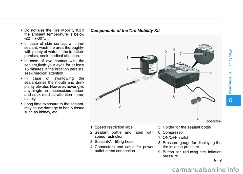
such as kidney, etc.Components of the Tire Mobility Kit
ODE067044
1. Speed restriction label
2. Sealant bottle and label with
speed restriction
3. Sealant/Air filling hose
4. Connectors and cable for power
outlet direct connection5. Holder for the sealant bottle
6. Compressor
7. ON/OFF switch
8. Pressure gauge for displaying the
tire inflation pressure
9. Button for reducing tire inflation
pressure
Page 461 of 561
7-36
Maintenance
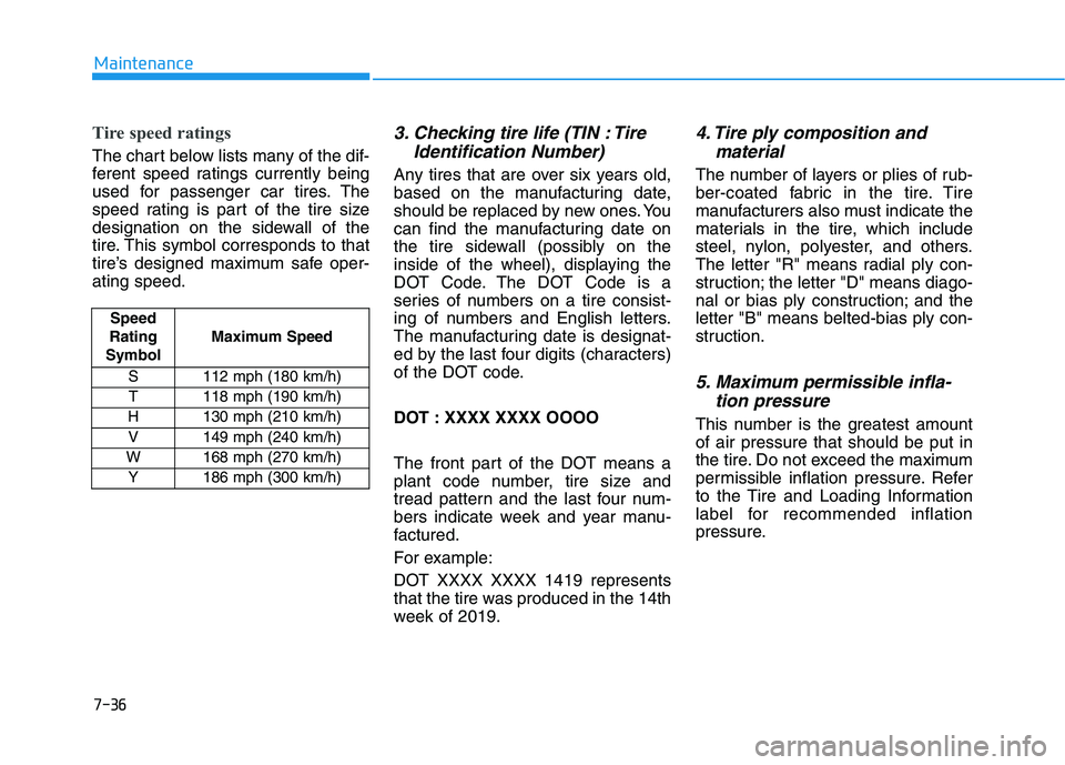
Tire speed ratings
The chart below lists many of the dif-
ferent speed ratings currently being
used for passenger car tires. The
speed rating is part of the tire size
designation on the sidewall of the
tire. This symbol corresponds to that
tire’s designed maximum safe oper-
ating speed.
3. Checking tire life (TIN : TireIdentification Number)
Any tires that are over six years old,
based on the manufacturing date,
should be replaced by new ones. You
can find the manufacturing date on
the tire sidewall (possibly on the
inside of the wheel), displaying the
DOT Code. The DOT Code is a
series of numbers on a tire consist-
ing of numbers and English letters.
The manufacturing date is designat-
ed by the last four digits (characters)
of the DOT code.
DOT : XXXX XXXX OOOO
The front part of the DOT means a
plant code number, tire size and
tread pattern and the last four num-
bers indicate week and year manu-
factured.
For example:
DOT XXXX XXXX 1419 represents
that the tire was produced in the 14th
week of 2019.
4. Tire ply composition andmaterial
The number of layers or plies of rub-
ber-coated fabric in the tire. Tire
manufacturers also must indicate the
materials in the tire, which include
steel, nylon, polyester, and others.
The letter "R" means radial ply con-
struction; the letter "D" means diago-
nal or bias ply construction; and the
letter "B" means belted-bias ply con-
struction.
5. Maximum permissible infla-tion pressure
This number is the greatest amount
of air pressure that should be put in
the tire. Do not exceed the maximum
permissible inflation pressure. Refer
to the Tire and Loading Information
label for recommended inflation
pressure.
Speed
Rating
Symbol Maximum Speed
S 112 mph (180 km/h) T 118 mph (190 km/h)
H 130 mph (210 km/h) V 149 mph (240 km/h)
W 168 mph (270 km/h)
Y186 mph (300 km/h)
Page 506 of 561
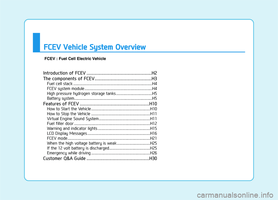
Introduction of FCEV .........................................................H2
The components of FCEV..................................................H3
Fuel cell stack ...................................................................................H4
FCEV system module .......................................................................H4
High pressure hydrogen storage tanks ......................................H5
Battery system..................................................................................H5
Features of FCEV .............................................................H10
How to Start the Vehicle ..............................................................H10
How to Stop the Vehicle ..............................................................H11
Virtual Engine Sound System......................................................H11
Fuel filler door ................................................................................H12
Warning and indicator lights .......................................................H15
LCD Display Messages ..................................................................H16
FCEV mode.......................................................................................H21
When the high voltage battery is weak ...................................H25
If the 12 volt battery is discharged...........................................H25
Emergency while driving ..............................................................H26
Customer Q&A Guide .......................................................H30
F FC
CE
EV
V
V
Ve
eh
hi
ic
cl
le
e
S
Sy
ys
st
te
em
m
O
Ov
ve
er
rv
vi
ie
ew
w
FCEV : Fuel Cell Electric Vehicle
Page 520 of 561
H15
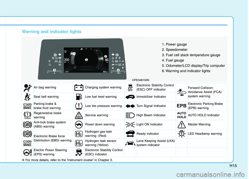
Warning and indicator lights
OFE048100N
1. Power gauge
2. Speedometer
3. Fuel cell stack temperature gauge
4. Fuel gauge
5. Odometer/LCD display/Trip computer
6. Warning and indicator lights
Air bag warningCharging system warningElectronic Stability Control
(ESC) OFF indicator Forward Collision-
Avoidance Assist (FCA)
system warning
Seat belt warningLow fuel level warning Immobilizer Indicator
Parking brake &
brake fluid warningLow tire pressure warningTurn Signal IndicatorEPBElectronic Parking Brake
(EPB) warning
Regenerative brake
warningService warning High Beam IndicatorAUTO
HOLDAUTO HOLD Indicator
Anti-lock brake system
(ABS) warningPower down warning Light ON IndicatorMaster Warning
Electronic Brake force
Distribution (EBD) warning
Hydrogen gas leak
warning (Red) Ready indicatorLED Headlamp warning
Hydrogen leak sensor
warning (Yellow)Lane Keeping Assist (LKA)
system indicator
Electric Power Steering
(EPS) warningElectronic Stability Control
(ESC) indicator
Yellow
❈For more details, refer to the ‘Instrument cluster’ in Chapter 3.