2020 Hyundai Ioniq Plug-in Hybrid lock
[x] Cancel search: lockPage 253 of 635

3-161
Convenient features of your vehicle
3
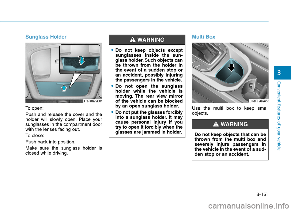
Sunglass Holder
To open:
Push and release the cover and the
holder will slowly open. Place your
sunglasses in the compartment door
with the lenses facing out.
To close:
Push back into position.
Make sure the sunglass holder is
closed while driving.
Multi Box
Use the multi box to keep small
objects.
OAD045413OAE046422
Do not keep objects except
sunglasses inside the sun-
glass holder. Such objects can
be thrown from the holder in
the event of a sudden stop or
an accident, possibly injuring
the passengers in the vehicle.
Do not open the sunglass
holder while the vehicle is
moving. The rear view mirror
of the vehicle can be blocked
by an open sunglass holder.
Do not put the glasses forcibly
into a sunglass holder. It may
cause personal injury if you
try to open it forcibly when the
glasses are jammed in holder.
WARNING
Do not keep objects that can be
thrown from the multi box and
severely injure passengers in
the vehicle in the event of a sud-
den stop or an accident.
WARNING
Page 255 of 635

3-163
Convenient features of your vehicle
3
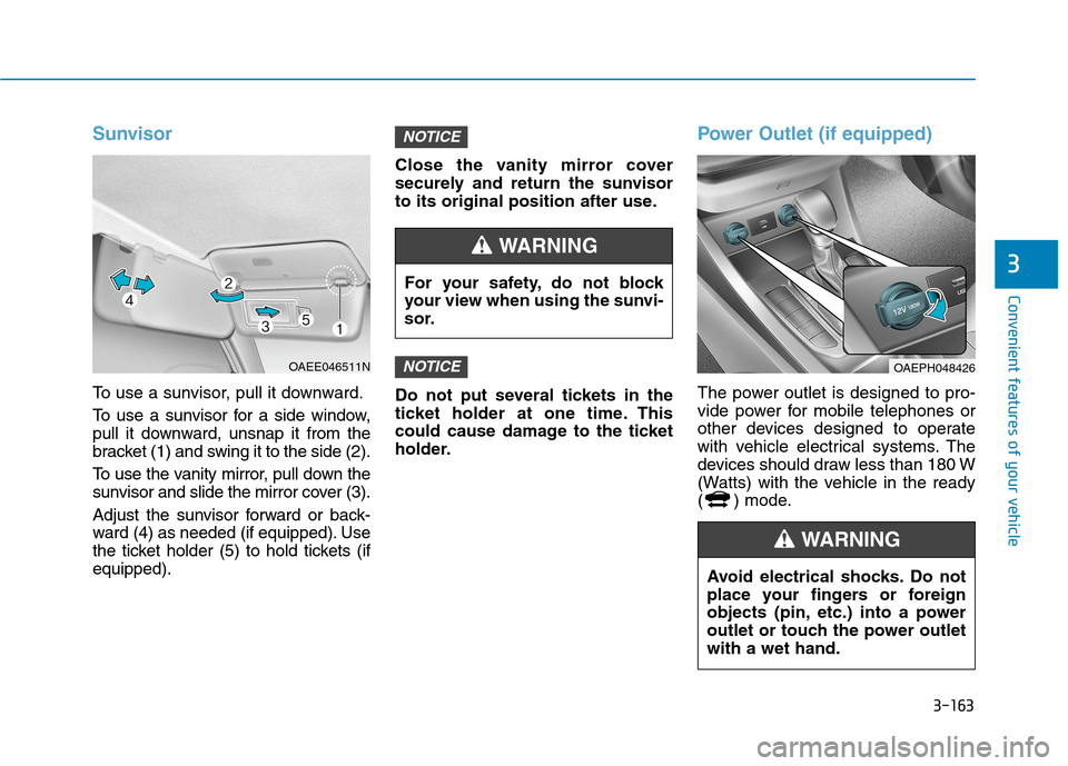
Sunvisor
To use a sunvisor, pull it downward.
To use a sunvisor for a side window,
pull it downward, unsnap it from the
bracket (1) and swing it to the side (2).
To use the vanity mirror, pull down the
sunvisor and slide the mirror cover (3).
Adjust the sunvisor forward or back-
ward (4) as needed (if equipped). Use
the ticket holder (5) to hold tickets (if
equipped).Close the vanity mirror cover
securely and return the sunvisor
to its original position after use.
Do not put several tickets in the
ticket holder at one time. This
could cause damage to the ticket
holder.
Power Outlet (if equipped)
The power outlet is designed to pro-
vide power for mobile telephones or
other devices designed to operate
with vehicle electrical systems. The
devices should draw less than 180 W
(Watts) with the vehicle in the ready
( ) mode.
NOTICE
NOTICE
OAEE046511N
For your safety, do not block
your view when using the sunvi-
sor.
WARNING
OAEPH048426
Avoid electrical shocks. Do not
place your fingers or foreign
objects (pin, etc.) into a power
outlet or touch the power outlet
with a wet hand.
WARNING
Page 257 of 635

3-165
Convenient features of your vehicle
3
To charge a cellular phone
The wireless cellular phone charging
system charges only the Qi-enabled
cellular phones ( ). Read the label
on the cellular phone accessory
cover or visit your cellular phone
manufacturer’s website to check
whether your cellular phone supports
the Qi technology.
The wireless charging process starts
when you put a Qi-enabled cellular
phone on the wireless charging unit.
1. Remove other items, including the
smart key, from the wireless charg-
ing unit. If not, the wireless charg-
ing process may be interrupted.
Place the cellular phone on the
center of charging pad.
2. The indicator light is orange when
the cellular phone is charging. The
indicator light turns green when
phone charging is completed.
3. You can turn ON or OFF the wire-
less charging function in the user
settings mode on the instrument
cluster. For further information,
refer to the "LCD Display Modes"
in this chapter.If your phone is not charging:
- Slightly change the position of the
cellular phone on the charging pad.
- Make sure the indicator light is
orange.
The indicator light will blink orange
for 10 seconds if there is a malfunc-
tion in the wireless charging system.
In this case, temporarily stop the
charging process, and re-attempt to
wirelessly charge your cellular phone
again.
The system warns you with a mes-
sage on the LCD display if the cellu-
lar phone is still on the wireless
charging unit after the ignition switch
is in the OFF position and the front
door is opened.
Information
For some manufacturers' cellular
phones, the system may not warn you
even though the cellular phone is left
on the wireless charging unit. This is
due to the particular characteristic of
the cellular phone and not a malfunc-
tion of the wireless charging. The wireless cellular phone
charging system may not sup-
port certain cellular phones,
which are not verified for the Qi
specification ( ).
When placing your cellular
phone on the charging mat,
position the phone in the middle
of the mat for optimal charging
performance. If your cell phone
is off to the side, the charging
rate may be less and in some
cases the cell phone may experi-
ence higher heat conduction.
In some cases, the wireless
charging may stop temporarily
when the Smart Key is used,
either when starting the vehicle
or locking/unlocking the doors,
etc.
When charging certain cellular
phones, the charging indicator
may not change to green when
the cell phone is fully charged.
(Continued)
NOTICE
i
Page 258 of 635

3-166
Convenient features of your vehicle
(Continued)
The wireless charging process
may temporarily stop, when tem-
perature abnormally increases
inside the wireless cellular
phone charging system. The
wireless charging process
restarts, when temperature falls
to a certain level.
The wireless charging process
may temporarily stop when
there is any metallic item, such
as a coin, between the wireless
cellular phone charging system
and a cellular phone.
For certain cellular phone with
their own protection, the wire-
less charging speed may
decrease and the wireless
charging may stop.
If the cellular phone has a thick
cover, the wireless charging may
not be possible.
If the cell phone is not complete-
ly contacting the charging pad,
wireless charging may not oper-
ate properly.
(Continued)(Continued)
Some magnetic items like credit
cards, phone cards or rail tickets
may be damaged if left with the
cellular phone during the charg-
ing process.
If the cellular phone without the
wireless charging function or
the metallic items are placed on
the charging pad, it may cause
slight noise. This noise does not
affect the cellular phone and the
vehicle, because this noise is an
operating sound during deter-
mining the item on the charging
pad.
If the ignition switch is in the
OFF position, the charging also
stops.
Clock
Vehicles with Audio system
Select the [SETUP]button on the
audio system ➟Select [Date/Time].
Set time: Set the time displayed on
the audio screen.
Time format: Choose between 12-
hour and 24-hour time formats. Do not adjust the clock while
driving, you may lose your
steering control and cause an
accident that results in severe
personal injury or death.
WARNING
Page 264 of 635

4-3
Infotainment System
4
Roof antenna
The roof antenna receives both AM
and FM broadcast signals, SXM sig-
nals (only type B). Rotate the roof
antenna in a counterclockwise direc-
tion to remove it. Rotate it in a clock-
wise direction to reinstall it. Before entering a place with a low
height clearance or a car wash,
remove the antenna by rotating it
counterclockwise. If not, the
antenna may be damaged.
When reinstalling your antenna,
it is important that it is fully
tightened and adjusted to the
upright position to ensure prop-
er reception.
Steering Wheel Audio Controls
Do not operate multiple audio
remote control buttons simultane-
ously.
NOTICE
NOTICE
OAE046438
OAEPH049481L
OAEPH049481N
■Type A
■Type B
Page 267 of 635

Driving your vehicle
5
Before driving.........................................................5-4
Before Entering the Vehicle ...........................................5-4
Before Starting ..................................................................5-4
Engine Start/Stop Button .....................................5-6
Engine Start/Stop Button Positions .............................5-7
Starting the Vehicle ..........................................................5-9
Turning Off the Vehicle .................................................5-11
Dual clutch transmission .....................................5-12
Dual Clutch Transmission Operation ..........................5-12
LCD display for transmission temperature and
warning message.............................................................5-14
Shift Lever Position ........................................................5-16
Parking ...............................................................................5-19
Good Driving Practices .................................................5-20
Paddle shifter .......................................................5-22
Regen B mode..................................................................5-22
Coasting guide .....................................................5-25
Braking system ...................................................5-26
Power Brakes ...................................................................5-26
Disc Brake Wear Indicator ............................................5-27
Parking Brake (foot type) .............................................5-27
Electronic Parking Brake (EPB)...................................5-29
AUTO HOLD ......................................................................5-35
Anti-lock Brake System (ABS) ....................................5-39
Electronic Stability Control (ESC)................................5-41Vehicle Stability Management (VSM).........................5-44
Hill-Start Assist Control (HAC) ....................................5-46
Good Braking Practices ................................................5-46
Forward Collision-Avoidance Assist (FCA)
- Front view camera only ...................................5-47
System setting and activation......................................5-47
FCA Warning Message and Brake Control ...............5-49
FCA sensor (Front view camera) ................................5-52
System malfunction ........................................................5-53
Limitations of the System .............................................5-55
Forward Collision-Avoidance Assist (FCA)
- Sensor fusion ....................................................5-61
System setting and activation......................................5-61
FCA warning message and brake control .................5-63
FCA sensor (Front view camera+ Front radar) .......5-66
System malfunction ........................................................5-68
Limitations of the system .............................................5-70
Lane Keeping Assist (LKA) .................................5-77
LKA operation ..................................................................5-79
Warning light and message ..........................................5-82
Limitations of the System .............................................5-83
LKA system function change .......................................5-85
Blind-spot Collision Warning (BCW) ................5-86
System description .........................................................5-86
System setting and operation ......................................5-87
Page 270 of 635

5-4
Driving your vehicle
Before Entering the Vehicle
• Be sure all windows, outside mir-
ror(s), and outside lights are clean
and unobstructed.
Remove frost, snow, or ice.
Visually check the tires for uneven
wear and damage.
Check under the vehicle for any
sign of leaks.
Be sure there are no obstacles
behind you if you intend to back up.
Before Starting
Make sure the hood, the liftgate,
and the doors are securely closed
and locked.
Adjust the position of the seat and
steering wheel.
Adjust the inside and outside
rearview mirrors.
Verify all the lights work.
Fasten your seatbelt. Check that all
passengers have fastened their
seatbelts.
Check the gauges and indicators in
the instrument panel and the mes-
sages on the instrument display
when the Engine Start/Stop button
is in the ON position.
Check that any items you are car-
rying are stored properly or fas-
tened down securely. CALIFORNIA PROPOSITION 65
WARNING
Engine exhaust and a wide vari-
ety of automobile components
including components found in
the interior furnishings in a
vehicle, contain or emit harmful
chemicals known to the State of
California to cause cancer and
birth defects and reproductive
harm. In addition, certain fluids
contained in vehicles and cer-
tain products of components
contain or emit chemicals
known to the State of California
to cause cancer and birth
defects or other reproductive
harm.WARNING
B BE
EF
FO
OR
RE
E
D
DR
RI
IV
VI
IN
NG
G
Page 282 of 635

5-16
Driving your vehicle
The warning will display a time to
wait for the transmission to cool.
If this occurs, pull over to a safe
location, stop the vehicle with the
engine running, apply the brakes
and shift the vehicle to P (Park),
and allow the transmission to cool.
When the message "Trans cooled.
Resume driving." appears you can
continue to drive your vehicle.
When possible, drive the vehicle
smoothly.
If any of the warning messages in
the LCD display continue to blink, for
your safety, contact an authorized
HYUNDAI dealer and have the sys-
tem checked.
Shift Lever Position
P (Park)
Always come to a complete stop
before shifting into P (Park).
To shift from P (Park), you must depr
ess firmly on the brake pedal and
make sure your foot is off the accel-
erator pedal.
If you have done all of the above
and still cannot shift the lever out
of P (Park), see "Shift-Lock
Release" in this section.
The shift lever must be in P (Park)
before turning the vehicle off.Shifting into P (Park) while the
vehicle is in motion may
cause you to lose control of
the vehicle.
After the vehicle has stopped,
always make sure the shift
lever is in P (Park), apply the
parking brake, and turn the
vehicle off.
When parking on an incline,
place the shift lever in Park
and apply the parking brake to
prevent the vehicle from
rolling downhill.
Do not use the P (Park) posi-
tion in place of the parking
brake.
WARNING