2020 DODGE CHARGER lock
[x] Cancel search: lockPage 183 of 412
STARTING AND OPERATING181
Remove your foot from the accelerator pedal. If
you do not, the vehicle may continue to
accelerate beyond the set speed. If this occurs:
The message “DRIVER OVERRIDE” will
display in the instrument cluster display.
The system will not be controlling the
distance between your vehicle and the
vehicle ahead. The vehicle speed will only be
determined by the position of the accelerator
pedal.
TO CANCEL
The following conditions cancel the system:
The brake pedal is applied.
The CANC button is pushed.
An Anti-Lock Brake System (ABS) event
occurs.
The gear selector is removed from the DRIVE
position.
The braking temperature exceeds normal
range (overheated).
The Electronic Stability Control/Traction
Control System (ESC/TCS) activates.
The vehicle parking brake is applied.
Driver seat belt is unbuckled at low speeds.
Driver door is opened at low speeds.
The driver switches ESC to Full Off mode.
NOTE:
If your vehicle stays at standstill for longer than
two seconds, then the system will cancel and
the brake force will be ramped-out. The driver
will have to apply the brakes to keep the vehicle
at a standstill.
TO TURN OFF
The system will turn off and clear the set speed
in memory if:
The Adaptive Cruise Control (ACC) on/off
button is pushed.
The Normal (Fixed Speed) Cruise Control on/
off button is pushed.
The ignition is placed in the OFF position.
TO RESUME
If there is a set speed in memory push the RES
(resume) button and then remove your foot
from the accelerator pedal. The instrument
cluster display will display the last set speed.
NOTE:
ACC cannot be resumed if there is a stationary
vehicle in front of your vehicle in close proximity.
TO VARY THE ACC SPEED
To Increase Speed
While ACC is set, you can increase the set speed
by pushing the SET (+) button.
WARNING!
The Resume function should only be used if
traffic and road conditions permit. Resuming
a set speed that is too high or too low for
prevailing traffic and road conditions could
cause the vehicle to accelerate or decelerate
too sharply for safe operation. Failure to
follow these warnings can result in a collision
and death or serious personal injury.5
20_LD_OM_EN_USC_t.book Page 181
Page 188 of 412

186STARTING AND OPERATING
To keep the ACC system operating properly, it is
important to note the following maintenance
items:
Always keep the sensor clean. Carefully wipe
the sensor lens with a soft cloth. Be cautious
not to damage the sensor lens.
Do not remove any screws from the sensor.
Doing so could cause an ACC system
malfunction or failure and require a sensor
realignment.
If the sensor or front end of the vehicle is
damaged due to a collision, see an autho -
rized dealer for service.
Do not attach or install any accessories near
the sensor, including transparent material or
aftermarket grilles. Doing so could cause an
ACC system failure or malfunction.
When the condition that deactivated the system
is no longer present, the system will return to
the “Adaptive Cruise Control Off” state and will
resume function by simply reactivating it. NOTE:
If the “ACC/FCW Unavailable Wipe Front
Radar Sensor” message occurs frequently
(e.g. more than once on every trip) without
any snow, rain, mud, or other obstruction,
have the radar sensor realigned at an autho
-
rized dealer.
Installing a snow plow, front-end protector,
an aftermarket grille or modifying the grille is
not recommended. Doing so may block the
sensor and inhibit ACC/FCW operation.
“Clean Front Windshield” Warning
The “ACC/FCW Limited Functionality Clean
Front Windshield” warning will display and also
a chime will indicate when conditions
temporarily limit system performance. This
most often occurs at times of poor visibility,
such as in snow or heavy rain and fog. The ACC
system may also become temporarily blinded
due to obstructions, such as mud, dirt, or ice on
windshield and fog on the inside of glass. In
these cases, the instrument cluster display will
display “ACC/FCW Limited Functionality Clean
Front Windshield” and the system will have
degraded performance. The “ACC/FCW Limited Functionality Clean
Front Windshield” message can sometimes be
displayed while driving in adverse weather
conditions. The ACC/FCW system will recover
after the vehicle has left these areas. Under
rare conditions, when the camera is not
tracking any vehicles or objects in its path this
warning may temporarily occur.
If weather conditions are not a factor, the driver
should examine the windshield and the camera
located on the back side of the inside rearview
mirror. They may require cleaning or removal of
an obstruction.
When the condition that created limited
functionality is no longer present, the system
will return to full functionality.
NOTE:
If the “ACC/FCW Limited Functionality Clean
Front Windshield” message occurs frequently
(e.g. more than once on every trip) without any
snow, rain, mud, or other obstruction, have the
windshield and forward facing camera
inspected at an authorized dealer.
20_LD_OM_EN_USC_t.book Page 186
Page 201 of 412
STARTING AND OPERATING199
CHANGING LANESENSE STATUS
The LaneSense system settings can be
configured through the Uconnect system
screen.
Follow these steps to change the LaneSense
settings:
1. Press the “Controls” button located on the
bottom of the Uconnect touchscreen
display.
2. Press the “Settings” button.
3. Press the “Safety & Driving Assistance” button.
When in the Safety & Driving Assistance screen,
you can configure the intensity of the torque
warning and the warning zone sensitivity (early/
late) through the personalization settings.
NOTE:
When enabled the system operates above
37 mph (60 km/h) and below 112 mph (180 km/h).
Use of the turn signal suppresses the warn -
ings.
The system will not apply torque to the
steering wheel whenever a safety system
engages. (Anti-Lock Brakes, Traction Control
System, Electronic Stability Control, Forward
Collision Warning, etc.)
PARKVIEW REAR BACK UP CAMERA
Your vehicle is equipped with the ParkView Rear
Back Up Camera that allows you to see an
on-screen image of the rear surroundings of
your vehicle whenever the gear selector is put
into REVERSE. The ParkView camera is located
on the rear of the vehicle above the rear license
plate. The image will be displayed in the
touchscreen display along with a caution note
to “Check Entire Surroundings” across the top
of the screen. After five seconds, this note will
disappear.
NOTE:
The ParkView Rear Back Up Camera has
programmable modes of operation that may be
selected through the Uconnect system. Refer to
“Uconnect Settings” in “Multimedia” for further
information. If your vehicle is equipped with the Camera
Delay feature and it is turned on, the rear
camera image will be displayed for up to 10
seconds when the vehicle is shifted out of
REVERSE. However, this feature is canceled if
the forward vehicle speed exceeds 8 mph
(13 km/h), the transmission is shifted into
PARK, the vehicle's ignition is placed in the OFF
position, or by pressing the image defeat “X”
button.
If your vehicle is not equipped with the Camera
Delay feature, or it is turned off, when the
vehicle is shifted out of REVERSE the rear
camera mode is exited and the previous
touchscreen display appears again.
When enabled, active guidelines are overlaid on
the image to illustrate the width of the vehicle
and its projected backup path based on the
steering wheel position. The active guidelines
will show separate zones that will help indicate
the distance to the rear of the vehicle.
5
20_LD_OM_EN_USC_t.book Page 199
Page 203 of 412
STARTING AND OPERATING201
2. Push near the rear edge and center of the of
the fuel filler door to release. The door will
pop open to allow hand access to open the
door the rest of the way.
Fuel Filler Door
3. Open the fuel filler door.
Fuel Filler
NOTE:
In certain cold conditions, ice may prevent the
fuel door from opening. If this occurs, lightly
push on the fuel door to break the ice buildup.
4. There is no fuel filler cap. A flapper door
inside the pipe seals the system.
5. Insert the fuel nozzle fully into the filler pipe – the nozzle opens and holds the flapper
door while refueling.
6. Fill the vehicle with fuel – when the fuel nozzle “clicks” or shuts off the fuel tank is
full.
7. Maintain nozzle in filler for five seconds to allow nozzle to drain.
8. Remove the fuel nozzle and close the fuel door.
9. To close the fuel filler door, push the center-rear edge (three o’clock position) of
the fuel filler door then release.
NOTE:
A funnel is provided (located in the trunk in the
spare tire area) to open the flapper door to allow
for emergency refueling with a gas can.
Fuel Funnel
WARNING!
Never have any smoking materials lit in or
near the vehicle when the fuel door is open
or the tank is being filled.
Never add fuel when the engine is running.
This is in violation of most state and federal
fire regulations and may cause the
“Malfunction Indicator Light” to turn on.
A fire may result if fuel is pumped into a
portable container that is inside of a
vehicle. You could be burned. Always place
fuel containers on the ground while filling.
5
20_LD_OM_EN_USC_t.book Page 201
Page 208 of 412
206STARTING AND OPERATING
(Continued)
TRAILER AND TONGUE WEIGHT
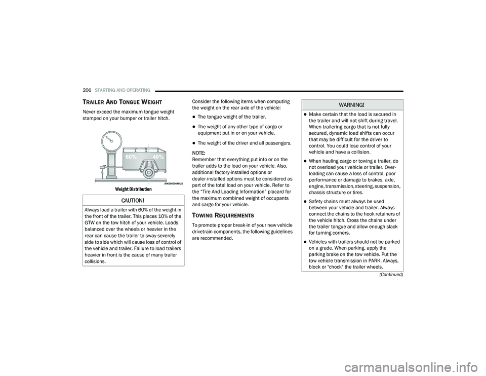
Never exceed the maximum tongue weight
stamped on your bumper or trailer hitch.
Weight Distribution
Consider the following items when computing
the weight on the rear axle of the vehicle:The tongue weight of the trailer.
The weight of any other type of cargo or
equipment put in or on your vehicle.
The weight of the driver and all passengers.
NOTE:
Remember that everything put into or on the
trailer adds to the load on your vehicle. Also,
additional factory-installed options or
dealer-installed options must be considered as
part of the total load on your vehicle. Refer to
the “Tire And Loading Information” placard for
the maximum combined weight of occupants
and cargo for your vehicle.
TOWING REQUIREMENTS
To promote proper break-in of your new vehicle
drivetrain components, the following guidelines
are recommended.
CAUTION!
Always load a trailer with 60% of the weight in
the front of the trailer. This places 10% of the
GTW on the tow hitch of your vehicle. Loads
balanced over the wheels or heavier in the
rear can cause the trailer to sway severely
side to side which will cause loss of control of
the vehicle and trailer. Failure to load trailers
heavier in front is the cause of many trailer
collisions.
WARNING!
Make certain that the load is secured in
the trailer and will not shift during travel.
When trailering cargo that is not fully
secured, dynamic load shifts can occur
that may be difficult for the driver to
control. You could lose control of your
vehicle and have a collision.
When hauling cargo or towing a trailer, do
not overload your vehicle or trailer. Over -
loading can cause a loss of control, poor
performance or damage to brakes, axle,
engine, transmission, steering, suspension,
chassis structure or tires.
Safety chains must always be used
between your vehicle and trailer. Always
connect the chains to the hook retainers of
the vehicle hitch. Cross the chains under
the trailer tongue and allow enough slack
for turning corners.
Vehicles with trailers should not be parked
on a grade. When parking, apply the
parking brake on the tow vehicle. Put the
tow vehicle transmission in PARK. Always,
block or "chock" the trailer wheels.
20_LD_OM_EN_USC_t.book Page 206
Page 213 of 412
STARTING AND OPERATING211
(Continued)
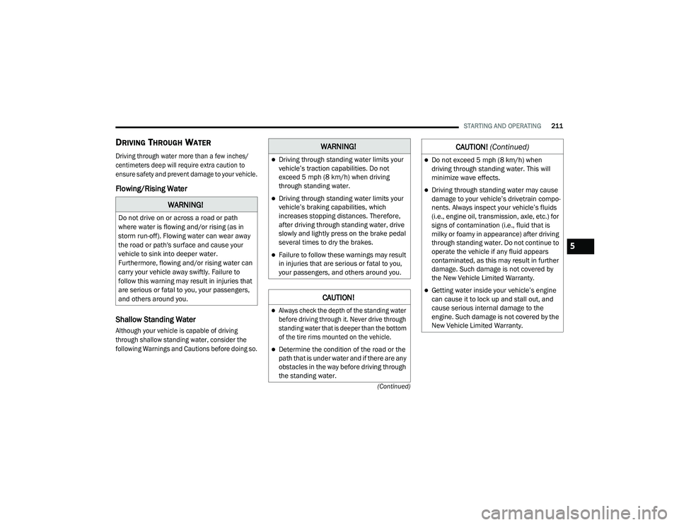
DRIVING THROUGH WATER
Driving through water more than a few inches/
centimeters deep will require extra caution to
ensure safety and prevent damage to your vehicle.
Flowing/Rising Water
Shallow Standing Water
Although your vehicle is capable of driving
through shallow standing water, consider the
following Warnings and Cautions before doing so.
WARNING!
Do not drive on or across a road or path
where water is flowing and/or rising (as in
storm run-off). Flowing water can wear away
the road or path's surface and cause your
vehicle to sink into deeper water.
Furthermore, flowing and/or rising water can
carry your vehicle away swiftly. Failure to
follow this warning may result in injuries that
are serious or fatal to you, your passengers,
and others around you.
WARNING!
Driving through standing water limits your
vehicle’s traction capabilities. Do not
exceed 5 mph (8 km/h) when driving
through standing water.
Driving through standing water limits your
vehicle’s braking capabilities, which
increases stopping distances. Therefore,
after driving through standing water, drive
slowly and lightly press on the brake pedal
several times to dry the brakes.
Failure to follow these warnings may result
in injuries that are serious or fatal to you,
your passengers, and others around you.
CAUTION!
Always check the depth of the standing water
before driving through it. Never drive through
standing water that is deeper than the bottom
of the tire rims mounted on the vehicle.
Determine the condition of the road or the
path that is under water and if there are any
obstacles in the way before driving through
the standing water.
Do not exceed 5 mph (8 km/h) when
driving through standing water. This will
minimize wave effects.
Driving through standing water may cause
damage to your vehicle’s drivetrain compo -
nents. Always inspect your vehicle’s fluids
(i.e., engine oil, transmission, axle, etc.) for
signs of contamination (i.e., fluid that is
milky or foamy in appearance) after driving
through standing water. Do not continue to
operate the vehicle if any fluid appears
contaminated, as this may result in further
damage. Such damage is not covered by
the New Vehicle Limited Warranty.
Getting water inside your vehicle’s engine
can cause it to lock up and stall out, and
cause serious internal damage to the
engine. Such damage is not covered by the
New Vehicle Limited Warranty.
CAUTION! (Continued)
5
20_LD_OM_EN_USC_t.book Page 211
Page 221 of 412

IN CASE OF EMERGENCY219
REPLACING EXTERIOR BULBS
Front Low/High Beam Headlamp — Models
With Halogen Headlamps
1. Open the hood.
Headlamp Assembly Dust Cap Location
NOTE:
Removal of the air cleaner filter housing may be
necessary prior to replacing bulbs in the head -
lamp assembly on the driver side of the vehicle.
2. Remove the large dust cap from the headlamp housing by turning it counter -
clockwise.
3. Turn the bulb counterclockwise, and remove.
Headlamp Assembly
4. Disconnect the bulb from the socket assembly and install the replacement bulb.
5. Reinstall the bulb and socket assembly into the headlamp assembly, and then turn it
clockwise.
6. Reinstall the dust cap.
Front Low/High Beam Headlamp — Models
With High Intensity Discharge (HID)
Headlamps
The headlamps are a type of high voltage
discharge tube. High voltage can remain in the
circuit even with the headlamp switch off and
the key removed. Because of this, you should
not attempt to service a headlamp bulb
yourself. If a headlamp bulb fails, take your
vehicle to an authorized dealer for service.
NOTE:
On vehicles equipped with HID headlamps,
when the headlamps are turned on, there is a
blue hue to the lights. This diminishes and
becomes more white after approximately 10
seconds, as the system charges.
CAUTION!
Do not touch the new bulb with your fingers.
Oil contamination will severely shorten bulb
life. If the bulb comes in contact with any oily
surface, clean the bulb with rubbing alcohol.
WARNING!
A transient high voltage occurs at the bulb
sockets of HID headlamps when the
headlamp switch is turned ON. It may cause
serious electrical shock or electrocution if not
serviced properly. See an authorized dealer
for service.
6
20_LD_OM_EN_USC_t.book Page 219
Page 224 of 412

222IN CASE OF EMERGENCY
CavityCartridge Fuse Mini-Fuse Description
F1––Fuse – Spare
F2 40 Amp Green –Radiator Fan #1 – (Non 6.2L Supercharged)
F3 50 Amp Red –Electric Power Steering #1 – If Equipped
F4 30 Amp Pink –Starter
F5 40 Amp Green –Anti-Lock Brakes
F6 30 Amp Pink –Anti-Lock Brakes
F7 20 Amp Blue –Police Ignition Run / ACC #1
F8 50 Amp Red / 20 Amp
Blue –Radiator Fan (6.2L Supercharged) / Police Ignition
Run / ACC # 2
F9 –20 Amp Yellow All-Wheel Drive Module – If Equipped
F10 –10 Amp RedIntrusion MOD (300) – If Equipped / Under Hood
Lamp – Police
F11 –20 Amp Yellow Horns
F12 –10 Amp Red Air Conditioning Clutch
F13 ––Fuse – Spare
F14 ––Fuse – Spare
F15 –20 Amp Yellow LH HID Headlamp – If Equipped
F16 –20 Amp Yellow RH HID Headlamp – If Equipped
20_LD_OM_EN_USC_t.book Page 222