2020 DODGE CHARGER turn signal
[x] Cancel search: turn signalPage 159 of 412

SAFETY157
(Continued)
PERIODIC SAFETY CHECKS YOU SHOULD
M
AKE OUTSIDE THE VEHICLE
Tires
Examine tires for excessive tread wear and
uneven wear patterns. Check for stones, nails,
glass, or other objects lodged in the tread or
sidewall. Inspect the tread for cuts and cracks.
Inspect sidewalls for cuts, cracks, and bulges.
Check the wheel nuts for tightness. Check the
tires (including spare) for proper cold inflation
pressure.
Lights
Have someone observe the operation of brake
lights and exterior lights while you work the
controls. Check turn signal and high beam
indicator lights on the instrument panel.
ONLY use the driver’s side floor mat on the
driver’s side floor area. To check for inter -
ference, with the vehicle properly parked
with the engine off, fully depress the accel -
erator, the brake, and the clutch pedal (if
present) to check for interference. If your
floor mat interferes with the operation of
any pedal, or is not secure to the floor,
remove the floor mat from the vehicle and
place the floor mat in your trunk.
ONLY use the passenger’s side floor mat on
the passenger’s side floor area.
ALWAYS make sure objects cannot fall or slide
into the driver’s side floor area when the
vehicle is moving. Objects can become trapped
under accelerator, brake, or clutch pedals and
could cause a loss of vehicle control.
WARNING! (Continued)
NEVER place any objects under the floor
mat (e.g., towels, keys, etc.). These objects
could change the position of the floor mat
and may cause interference with the accel -
erator, brake, or clutch pedals.
If the vehicle carpet has been removed and
re-installed, always properly attach carpet
to the floor and check the floor mat
fasteners are secure to the vehicle carpet.
Fully depress each pedal to check for inter -
ference with the accelerator, brake, or
clutch pedals then re-install the floor mats.
It is recommended to only use mild soap
and water to clean your floor mats. After
cleaning, always check your floor mat has
been properly installed and is secured to
your vehicle using the floor mat fasteners
by lightly pulling mat.
WARNING! (Continued)
4
20_LD_OM_EN_USC_t.book Page 157
Page 186 of 412
184STARTING AND OPERATING
The maximum braking applied by ACC is limited;
however, the driver can always apply the brakes
manually, if necessary.
NOTE:
The brake lights will illuminate whenever the
ACC system applies the brakes.
A Proximity Warning will alert the driver if ACC
predicts that its maximum braking level is not
sufficient to maintain the set distance. If this
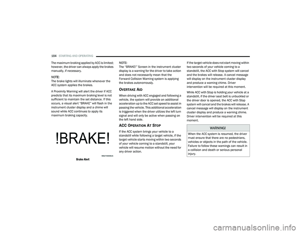
occurs, a visual alert “BRAKE” will flash in the
instrument cluster display and a chime will
sound while ACC continues to apply its
maximum braking capacity.
Brake Alert
NOTE:
The “BRAKE!” Screen in the instrument cluster
display is a warning for the driver to take action
and does not necessarily mean that the
Forward Collision Warning system is applying
the brakes autonomously.
OVERTAKE AID
When driving with ACC engaged and following a
vehicle, the system will provide an additional
acceleration up to the ACC set speed to assist in
passing the vehicle. This additional acceleration
is triggered when the driver utilizes the left turn
signal and will only be active when passing on
the left hand side.
ACC OPERATION AT STOP
If the ACC system brings your vehicle to a
standstill while following a target vehicle, if the
target vehicle starts moving within two seconds
of your vehicle coming to a standstill, your
vehicle will resume motion without the need for
any driver action.
If the target vehicle does not start moving within
two seconds of your vehicle coming to a
standstill, the ACC with Stop system will cancel
and the brakes will release. A cancel message
will display on the instrument cluster display
and produce a warning chime. Driver
intervention will be required at this moment.
While ACC with Stop is holding your vehicle at a
standstill, if the driver seat belt is unbuckled or
the driver door is opened, the ACC with Stop
system will cancel and the brakes will release. A
cancel message will display on the instrument
cluster display and produce a warning chime.
Driver intervention will be required at this
moment.WARNING!
When the ACC system is resumed, the driver
must ensure that there are no pedestrians,
vehicles or objects in the path of the vehicle.
Failure to follow these warnings can result in
a collision and death or serious personal
injury.
20_LD_OM_EN_USC_t.book Page 184
Page 198 of 412

196STARTING AND OPERATING
(Continued)
object as a sensor problem, causing the
“PARKSENSE UNAVAILABLE SERVICE
REQUIRED” message to be shown in the
instrument cluster display.
LANESENSE — IF EQUIPPED
LANESENSE OPERATION
The LaneSense system is operational at speeds
above 37 mph (60 km/h) and below 112 mph
(180 km/h). The LaneSense system uses a
forward looking camera to detect lane markings
and measure vehicle position within the lane
boundaries.
When both lane markings are detected and the
driver unintentionally drifts out of the lane (no
turn signal applied), the LaneSense system
provides a haptic warning in the form of torque
applied to the steering wheel to prompt the
driver to remain within the lane boundaries. If
the driver continues to unintentionally drift out
of the lane, the LaneSense system provides a
visual warning through the instrument cluster
display to prompt the driver to remain within the
lane boundaries. The driver may manually override the haptic
warning by applying torque into the steering
wheel at any time.
When only a single lane marking is detected
and the driver unintentionally drifts across the
lane marking (no turn signal applied), the
LaneSense system provides visual warnings
through the instrument cluster display to
prompt the driver to remain within the lane.
When only a single lane marking is detected, a
haptic (torque) warning will not be provided.
NOTE:
When operating conditions have been met, the
LaneSense system will monitor if the driver’s
hands are on the steering wheel and provides
an audible warning to the driver when the
driver’s hands are not detected on the steering
wheel. The system will cancel if the driver does
not return their hands to the wheel.
TURNING LANESENSE ON OR OFF
The default status of LaneSense is off.
The LaneSense button is located on the center
stack below the Uconnect display.
WARNING!
Drivers must be careful when backing up
even when using the Rear Park Assist system.
Always check carefully behind your vehicle,
and be sure to check for pedestrians,
animals, other vehicles, obstructions, or blind
spots before backing up. You are responsible
for the safety of your surroundings and must
continue to pay attention while backing up.
Failure to do so can result in serious injury or
death.
CAUTION!
ParkSense is only a parking aid and it is
unable to recognize every obstacle,
including small obstacles. Parking curbs
might be temporarily detected or not
detected at all. Obstacles located above or
below the sensors will not be detected
when they are in close proximity.
The vehicle must be driven slowly when
using ParkSense in order to be able to stop
in time when an obstacle is detected. It is
recommended that the driver looks over
his/her shoulder when using ParkSense.
CAUTION!
(Continued)
20_LD_OM_EN_USC_t.book Page 196
Page 201 of 412
STARTING AND OPERATING199
CHANGING LANESENSE STATUS
The LaneSense system settings can be
configured through the Uconnect system
screen.
Follow these steps to change the LaneSense
settings:
1. Press the “Controls” button located on the
bottom of the Uconnect touchscreen
display.
2. Press the “Settings” button.
3. Press the “Safety & Driving Assistance” button.
When in the Safety & Driving Assistance screen,
you can configure the intensity of the torque
warning and the warning zone sensitivity (early/
late) through the personalization settings.
NOTE:
When enabled the system operates above
37 mph (60 km/h) and below 112 mph (180 km/h).
Use of the turn signal suppresses the warn -
ings.
The system will not apply torque to the
steering wheel whenever a safety system
engages. (Anti-Lock Brakes, Traction Control
System, Electronic Stability Control, Forward
Collision Warning, etc.)
PARKVIEW REAR BACK UP CAMERA
Your vehicle is equipped with the ParkView Rear
Back Up Camera that allows you to see an
on-screen image of the rear surroundings of
your vehicle whenever the gear selector is put
into REVERSE. The ParkView camera is located
on the rear of the vehicle above the rear license
plate. The image will be displayed in the
touchscreen display along with a caution note
to “Check Entire Surroundings” across the top
of the screen. After five seconds, this note will
disappear.
NOTE:
The ParkView Rear Back Up Camera has
programmable modes of operation that may be
selected through the Uconnect system. Refer to
“Uconnect Settings” in “Multimedia” for further
information. If your vehicle is equipped with the Camera
Delay feature and it is turned on, the rear
camera image will be displayed for up to 10
seconds when the vehicle is shifted out of
REVERSE. However, this feature is canceled if
the forward vehicle speed exceeds 8 mph
(13 km/h), the transmission is shifted into
PARK, the vehicle's ignition is placed in the OFF
position, or by pressing the image defeat “X”
button.
If your vehicle is not equipped with the Camera
Delay feature, or it is turned off, when the
vehicle is shifted out of REVERSE the rear
camera mode is exited and the previous
touchscreen display appears again.
When enabled, active guidelines are overlaid on
the image to illustrate the width of the vehicle
and its projected backup path based on the
steering wheel position. The active guidelines
will show separate zones that will help indicate
the distance to the rear of the vehicle.
5
20_LD_OM_EN_USC_t.book Page 199
Page 210 of 412
208STARTING AND OPERATING
Towing Requirements — Trailer Lights
And Wiring
Whenever you pull a trailer, regardless of the
trailer size, stoplights and turn signals on the
trailer are required for motoring safety.
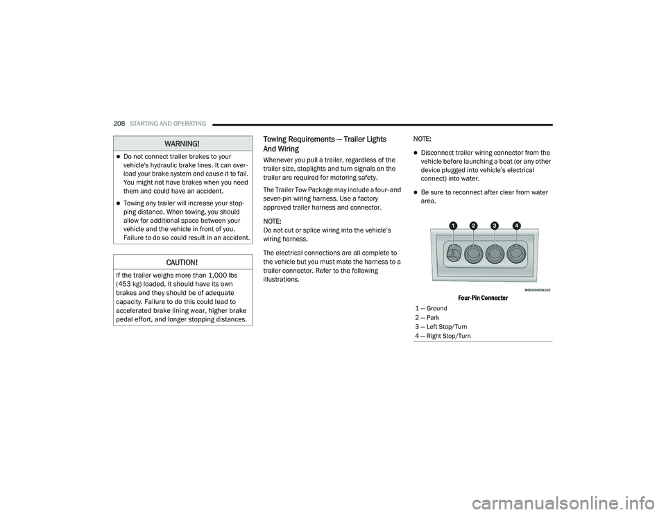
The Trailer Tow Package may include a four- and
seven-pin wiring harness. Use a factory
approved trailer harness and connector.
NOTE:
Do not cut or splice wiring into the vehicle’s
wiring harness.
The electrical connections are all complete to
the vehicle but you must mate the harness to a
trailer connector. Refer to the following
illustrations. NOTE:Disconnect trailer wiring connector from the
vehicle before launching a boat (or any other
device plugged into vehicle’s electrical
connect) into water.
Be sure to reconnect after clear from water
area.
Four-Pin Connector
WARNING!
Do not connect trailer brakes to your
vehicle's hydraulic brake lines. It can over -
load your brake system and cause it to fail.
You might not have brakes when you need
them and could have an accident.
Towing any trailer will increase your stop -
ping distance. When towing, you should
allow for additional space between your
vehicle and the vehicle in front of you.
Failure to do so could result in an accident.
CAUTION!
If the trailer weighs more than 1,000 lbs
(453 kg) loaded, it should have its own
brakes and they should be of adequate
capacity. Failure to do this could lead to
accelerated brake lining wear, higher brake
pedal effort, and longer stopping distances.
1 — Ground
2 — Park
3 — Left Stop/Turn
4 — Right Stop/Turn
20_LD_OM_EN_USC_t.book Page 208
Page 214 of 412
212
IN CASE OF EMERGENCY
HAZARD WARNING FLASHERS
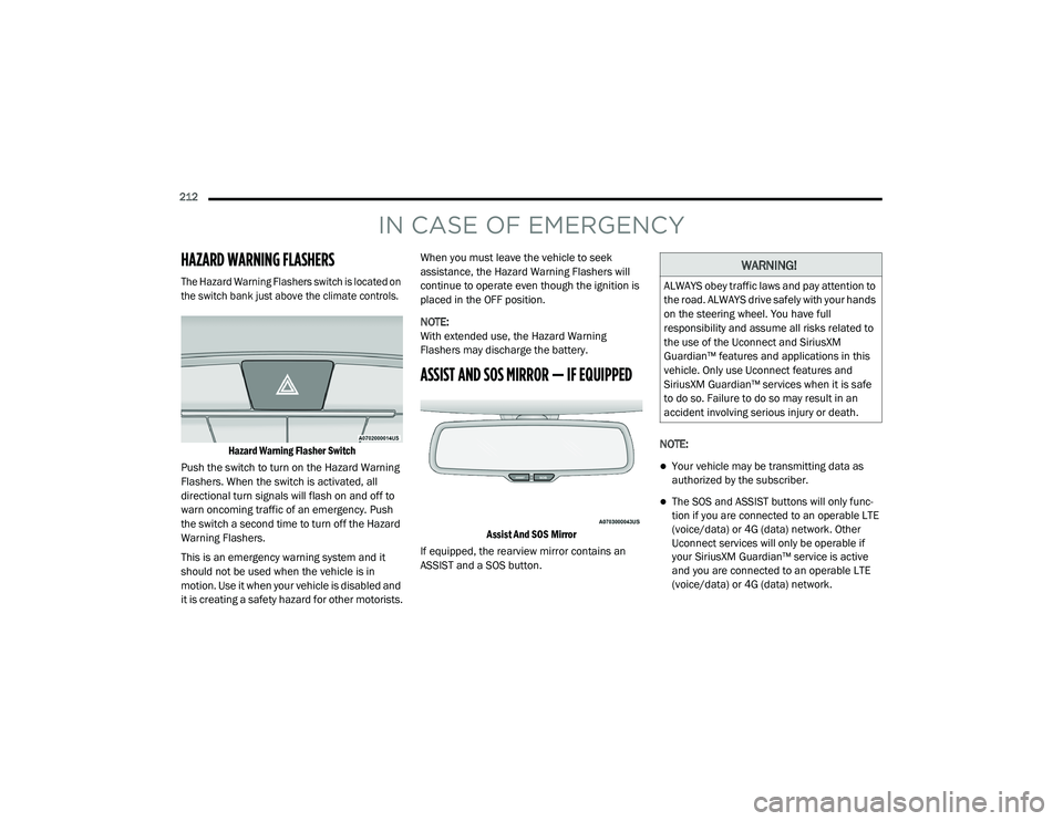
The Hazard Warning Flashers switch is located on
the switch bank just above the climate controls.Hazard Warning Flasher Switch
Push the switch to turn on the Hazard Warning
Flashers. When the switch is activated, all
directional turn signals will flash on and off to
warn oncoming traffic of an emergency. Push
the switch a second time to turn off the Hazard
Warning Flashers.
This is an emergency warning system and it
should not be used when the vehicle is in
motion. Use it when your vehicle is disabled and
it is creating a safety hazard for other motorists. When you must leave the vehicle to seek
assistance, the Hazard Warning Flashers will
continue to operate even though the ignition is
placed in the OFF position.
NOTE:
With extended use, the Hazard Warning
Flashers may discharge the battery.
ASSIST AND SOS MIRROR — IF EQUIPPED
Assist And SOS Mirror
If equipped, the rearview mirror contains an
ASSIST and a SOS button. NOTE:
Your vehicle may be transmitting data as
authorized by the subscriber.
The SOS and ASSIST buttons will only func
-
tion if you are connected to an operable LTE
(voice/data) or 4G (data) network. Other
Uconnect services will only be operable if
your SiriusXM Guardian™ service is active
and you are connected to an operable LTE
(voice/data) or 4G (data) network.
WARNING!
ALWAYS obey traffic laws and pay attention to
the road. ALWAYS drive safely with your hands
on the steering wheel. You have full
responsibility and assume all risks related to
the use of the Uconnect and SiriusXM
Guardian™ features and applications in this
vehicle. Only use Uconnect features and
SiriusXM Guardian™ services when it is safe
to do so. Failure to do so may result in an
accident involving serious injury or death.
20_LD_OM_EN_USC_t.book Page 212
Page 217 of 412
IN CASE OF EMERGENCY215
Even if the SOS Call system is fully functional,
factors beyond FCA US LLC’s control may
prevent or stop the SOS Call system operation.
These include, but are not limited to, the
following factors:
The ignition is in the OFF position.
The vehicle’s electrical systems are not
intact.
The SOS Call system software and/or hard -
ware are damaged during a crash.
The vehicle battery loses power or becomes
disconnected during a vehicle crash.
LTE (voice/data) or 4G (data) network and/or
Global Positioning Satellite signals are
unavailable or obstructed.
Equipment malfunction at the SOS operator
facility.
Operator error by the SOS operator.
LTE (voice/data) or 4G (data) network
congestion.
Weather.
Buildings, structures, geographic terrain, or
tunnels. NOTE:
Your vehicle may be transmitting data as
authorized by the subscriber.
Never place anything on or near the vehicle’s
LTE (voice/data) or 4G (data) and GPS
antennas. You could prevent LTE (voice/
data) or 4G (data) and GPS signal reception,
which can prevent your vehicle from placing
an emergency call. An operable LTE (voice/
data) or 4G (data) network connection and a
GPS signal is required for the SOS Call
system to function properly.
WARNING!
Ignoring the Rearview Mirror light could
mean you will not have SOS Call services. If
the Rearview Mirror light is illuminated,
have an authorized dealer service the SOS
Call system immediately.
The Occupant Restraint Control module
turns on the air bag Warning Light on the
instrument panel if a malfunction in any
part of the system is detected. If the Air Bag
Warning Light is illuminated, have an
authorized dealer service the Occupant
Restraint Control system immediately.
WARNING!
ALWAYS obey traffic laws and pay attention to
the road. ALWAYS drive safely with your hands
on the steering wheel. You have full
responsibility and assume all risks related to
the use of the Uconnect and SiriusXM
Guardian™ features and applications in this
vehicle. Only use Uconnect features and
SiriusXM Guardian™ services when it is safe
to do so. Failure to do so may result in an
accident involving serious injury or death.
6
20_LD_OM_EN_USC_t.book Page 215
Page 222 of 412

220IN CASE OF EMERGENCY
(Continued)
Front/Rear Side Marker Lamp
The Side Markers use LED lamps that are not
serviceable separately. The Side Markers must
be replaced as an assembly, see an authorized
dealer.
Front Fog Lamp
The Front Fog Lamps use LED sources that are
not serviceable separately. The Front Fog Lamp
must be replaced as an assembly; see an
authorized dealer.
Front Turn Signal Lamps
The Front Park/Turn function is part of the
headlamp assembly and use LED lamps that
are not serviceable separately. The headlamps
must be replaced as an assembly, see an
authorized dealer.
Backup Lamps
The Backup Lamps use LED sources that are
not serviceable separately. The Applique must
be replaced as an assembly; see an authorized
dealer.
License Lamp
The License Lamp uses an LED source that is
not serviceable separately. The License Lamp
must be replaced as an assembly; see an
authorized dealer.
Center High Mounted Stop Lamp (CHMSL)
The CHMSL Lamp uses LED sources that are
not serviceable separately. The CHMSL Lamp
must be replaced as an assembly; see an
authorized dealer.
FUSES
GENERAL INFORMATION
The fuses protect electrical systems against
excessive current.
When a device does not work, you must check
the fuse element inside the blade fuse for a
break/melt.
WARNING!
When replacing a blown fuse, always use
an appropriate replacement fuse with the
same amp rating as the original fuse. Never
replace a fuse with another fuse of higher
amp rating. Never replace a blown fuse with
metal wires or any other material. Do not
place a fuse inside a circuit breaker cavity
or vice versa. Failure to use proper fuses
may result in serious personal injury, fire
and/or property damage.
Before replacing a fuse, make sure that the
ignition is off and that all the other services
are switched off and/or disengaged.
If the replaced fuse blows again, contact an
authorized dealer.
If a general protection fuse for safety
systems (air bag system, braking system),
power unit systems (engine system, trans-
mission system) or steering system blows,
contact an authorized dealer.
WARNING! (Continued)
20_LD_OM_EN_USC_t.book Page 220