2020 DODGE CHARGER USB port
[x] Cancel search: USB portPage 9 of 412

7
MULTIMEDIA
UCONNECT SYSTEMS ....................................... 321
CYBERSECURITY ............................................... 321
UCONNECT SETTINGS ...................................... 322Customer Programmable Features —
Uconnect 4 Settings ..................................322 Customer Programmable Features —
Uconnect 4C/4C NAV Settings ................. 337
SAFETY AND GENERAL INFORMATION .......... 354
Safety Guidelines .......................................354
UCONNECT 4 WITH 7-INCH DISPLAY .............. 355
Introduction ................................................355
Radio Mode ................................................356
Media Mode ...............................................364Phone Mode ...............................................371
STEERING WHEEL AUDIO CONTROLS —
IF EQUIPPED ....................................................... 382
Radio Operation .........................................382
Media Mode ...............................................382
AUX/USB/MP3 CONTROL ................................ 383
RADIO OPERATION AND MOBILE PHONES.... 383
Regulatory And Safety Information........... 383 UCONNECT VOICE RECOGNITION
QUICK TIPS ......................................................... 385
Introducing Uconnect ................................ 385
Get Started ................................................. 385
Basic Voice Commands............................. 386Radio .......................................................... 386
Media.......................................................... 386
Phone ......................................................... 387Voice Text Reply — If Equipped ................. 387
Climate ....................................................... 388Navigation (4C NAV) .................................. 388Siri® Eyes Free — If Equipped ................. 388
Do Not Disturb .......................................... 388Android Auto™ — If Equipped ................... 389
Apple CarPlay® — If Equipped ................. 389
General Information .................................. 390Additional Information ............................... 390
CUSTOMER ASSISTANCE
SUGGESTIONS FOR OBTAINING SERVICE FOR
YOUR VEHICLE ...................................................391
Prepare For The Appointment................... 391
Prepare A List............................................. 391
Be Reasonable With Requests ................. 391 IF YOU NEED ASSISTANCE .............................. 391
FCA US LLC Customer Center ................... 392
FCA Canada Inc. Customer Center ........... 392
In Mexico Contact ...................................... 392
Puerto Rico And US
Virgin Islands ............................................. 392 Customer Assistance For The Hearing
Or Speech Impaired
(TDD/TTY) ................................................... 392 Service Contract ....................................... 392
WARRANTY INFORMATION .............................. 393
MOPAR PARTS................................................... 393
REPORTING SAFETY DEFECTS ........................ 393
In The 50 United States And
Washington, D.C. ....................................... 393 In Canada ................................................... 394
PUBLICATION ORDER FORMS ........................ 394
20_LD_OM_EN_USC_t.book Page 7
Page 81 of 412

GETTING TO KNOW YOUR VEHICLE79
(Continued)
(Continued)
Power Outlet Fuse Locations
NOTE:
The instrument panel power outlet and dual rear
console USB ports can be changed to “battery”
powered all the time by moving the #12 20 Amp
fuse from “IGN” to “B+”. Refer to “Fuses” in “In
Case Of Emergency” for further information.
SUNGLASSES BIN DOOR
At the front of the console a compartment is
provided for the storage of a pair of sunglasses.
The storage compartment access is a “push/
push” design. Push the chrome pad on the door
to open. Push the chrome pad on the door to
close.
Sunglasses Bin Door
1 — #12 Fuse 20 Amp Yellow Instrument Panel
Power Outlet/Dual USB Charge Only Ports
2 — #38 Fuse 20 Amp Yellow Center Console
Power Outlet/Media Hub
WARNING!
To avoid serious injury or death:
Only devices designed for use in this type of
outlet should be inserted into any 12 Volt
outlet.
Do not touch with wet hands.
Close the lid when not in use and while
driving the vehicle.
If this outlet is mishandled, it may cause an
electric shock and failure.
CAUTION!
Many accessories that can be plugged in draw
power from the vehicle's battery even when not
in use (i.e., cellular phones, etc.). Eventually, if
plugged in long enough, the vehicle's battery
will discharge sufficiently to degrade battery life
and/or prevent the engine from starting.
Accessories that draw higher power (i.e.,
coolers, vacuum cleaners, lights, etc.) will
degrade the battery even more quickly.
Only use these intermittently and with
greater caution.
After the use of high power draw accesso -
ries or long periods of the vehicle not being
started (with accessories still plugged in),
the vehicle must be driven a sufficient
length of time to allow the alternator to
recharge the vehicle's battery.
WARNING! (Continued)
Power outlets are designed for accessory
plugs only. Do not hang any type of acces -
sory or accessory bracket from the plug.
Improper use of the power outlet can cause
damage.
CAUTION! (Continued)
2
20_LD_OM_EN_USC_t.book Page 79
Page 95 of 412

GETTING TO KNOW YOUR INSTRUMENT PANEL93
Faults are displayed from newest to the
oldest.
If the menu is exited before the end of codes
is reached - when the driver re-enters the list
will be restarted from the beginning.
When no codes are present or the last code
is reached = (P0000) and this message is
displayed:
“No or End of Diagnostic Codes.”
BATTERY SAVER ON/BATTERY SAVER
M
ODE MESSAGE — ELECTRICAL LOAD
R
EDUCTION ACTIONS — IF EQUIPPED
This vehicle is equipped with an Intelligent
Battery Sensor (IBS) to perform additional
monitoring of the electrical system and status
of the vehicle battery.
In cases when the IBS detects charging system
failure, or the vehicle battery conditions are
deteriorating, electrical load reduction actions
will take place to extend the driving time and
distance of the vehicle. This is done by reducing
power to or turning off non-essential electrical
loads. Load reduction is only active when the engine is
running. It will display a message if there is a
risk of battery depletion to the point where the
vehicle may stall due to lack of electrical supply,
or will not restart after the current drive cycle.
When load reduction is activated, the message
“Battery Saver On” or “Battery Saver Mode” will
appear in the instrument cluster.
These messages indicate the vehicle battery
has a low state of charge and continues to lose
electrical charge at a rate that the charging
system cannot sustain.
NOTE:The charging system is independent from
load reduction. The charging system
performs a diagnostic on the charging
system continuously.
If the Battery Charge Warning Light is on it
may indicate a problem with the charging
system. Refer to “Battery Charge Warning
Light” in “Getting To Know Your Instrument
Panel” for further information.
The electrical loads that may be switched off
(if equipped), and vehicle functions which can
be affected by load reduction:
Heated Seat/Vented Seats/Heated Wheel
Heated/Cooled Cup Holders — If Equipped
Rear Defroster And Heated Mirrors
HVAC System
115 Volts AC Power Inverter System
Audio and Telematics System
Loss of the battery charge may indicate one or
more of the following conditions:
The charging system cannot deliver enough
electrical power to the vehicle system
because the electrical loads are larger than
the capability of the charging system. The
charging system is still functioning properly.
Turning on all possible vehicle electrical
loads (e.g. HVAC to max settings, exterior
and interior lights, overloaded power outlets
+12 Volts, 115 Volts AC, USB ports) during
certain driving conditions (city driving,
towing, frequent stopping).
3
20_LD_OM_EN_USC_t.book Page 93
Page 96 of 412

94GETTING TO KNOW YOUR INSTRUMENT PANEL
Installing options like additional lights,
upfitter electrical accessories, audio
systems, alarms and similar devices.
Unusual driving cycles (short trips separated
by long parking periods).
The vehicle was parked for an extended
period of time (weeks, months).
The battery was recently replaced and was
not charged completely.
The battery was discharged by an electrical
load left on when the vehicle was parked.
The battery was used for an extended period
with the engine not running to supply radio,
lights, chargers, +12 Volts portable appli-
ances like vacuum cleaners, game consoles
and similar devices. What to do when an electrical load reduction
action message is present (“Battery Saver On”
or “Battery Saver Mode”)
During a trip:
Reduce power to unnecessary loads if
possible:
Turn off redundant lights (interior or exte
-
rior)
Check what may be plugged in to power
outlets +12 Volts, 115 Volts AC, USB
ports
Check HVAC settings (blower, tempera -
ture)
Check the audio settings (volume) After a trip:
Check if any aftermarket equipment was
installed (additional lights, upfitter electrical
accessories, audio systems, alarms) and
review specifications if any (load and Ignition
Off Draw currents).
Evaluate the latest driving cycles (distance,
driving time and parking time).
The vehicle should have service performed if
the message is still present during consecu
-
tive trips and the evaluation of the vehicle
and driving pattern did not help to identify the
cause.
20_LD_OM_EN_USC_t.book Page 94
Page 228 of 412

226IN CASE OF EMERGENCY
F8 30 Amp Pink –Interior Lighting
F9 40 Amp Green –Power Locks
F10 30 Amp Pink –Driver Door Control Module
F11 30 Amp Pink –Passenger Door Control Module
F12 –20 Amp YellowCigar Lighter/IP APO/RR USB
(Selectable Fuse)– If Equipped
F15 40 Amp Green –HVAC Blower
F16 20 Amp Blue –Left Spot Lamp – Police
F17 20 Amp Blue –Right Spot Lamp – Police
F18 30 Amp Pink –VISM Mod (Police)
F19 ––Fuse – Spare
F20 ––Fuse – Spare
F21 30 Amp Pink –Fuel Pump (Non 6.2L ADR)
F22 –5 Amp Tan Cyber Gateway Mod
F23 –10 Amp RedFuel Door – If Equipped/Diagnostic
Port
F24 –10 Amp RedIntegrated Center Stack
F25 –10 Amp Red Tire Pressure Monitor
F26 –15 Amp BlueTrans Mod (Charger Non- Police/
300)
F27 –25 Amp Clear Amplifier – If Equipped
CavityCartridge Fuse Mini-FuseDescription
20_LD_OM_EN_USC_t.book Page 226
Page 366 of 412

364MULTIMEDIA
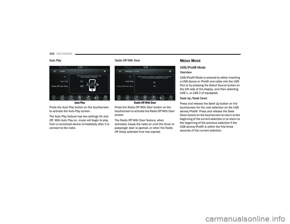
Auto Play
Auto Play
Press the Auto Play button on the touchscreen
to activate the Auto Play screen.
The Auto Play feature has two settings On and
Off. With Auto Play on, music will begin to play
from a connected device immediately after it is
connect to the radio. Radio Off With Door
Radio Off With Door
Press the Radio Off With Door button on the
touchscreen to activate the Radio Off With Door
screen.
The Radio Off With Door feature, when
activated, keeps the radio on until the driver or
passenger door is opened, or when the Radio
Off Delay selected time has expired.MEDIA MODE
USB/iPod® Mode
Overview
USB/iPod® Mode is entered by either inserting
a USB device or iPod® and cable into the USB
Port or by pressing the Select Source button on
the left side of the display, and then selecting
USB 1, or USB 2 (if equipped).
Seek Up /Seek Down
Press and release the Seek Up button on the
touchscreen for the next selection on the USB
device/iPod®. Press and release the Seek
Down button on the touchscreen to return to the
beginning of the current selection or to return to
the beginning of the previous selection if the
USB device/iPod® is within the first three
seconds of the current selection.
20_LD_OM_EN_USC_t.book Page 364
Page 367 of 412

MULTIMEDIA365
Browse
Press the Browse button on the touchscreen to
display the browse window. The left side of the
browse window displays a list of ways you can
browse through the contents of the USB device/
iPod®. If supported by the device, you can
browse by Folders, Artists, Playlists, Albums,
Songs, etc. Press the desired button on the left
side of the screen. The center of the browse
window shows items and its sub-functions,
which can be scrolled by pressing the Up and
Down buttons to the right. The Tune/Scroll knob
can also be used to scroll.
Media Mode
Press the Media button on the touchscreen to
select the desired audio source: USB.
Repeat
Press the Repeat button on the touchscreen to
toggle the repeat functionality. The Repeat
button on the touchscreen is highlighted when
active. The Radio will continue to play the current
track, repeatedly, as long as the repeat is active.
Press the Repeat button on the touchscreen a
second time to turn this feature off.
Shuffle
Press the Shuffle button on the touchscreen to
play the selections on the USB/iPod® device in
random order to provide an interesting change of
pace. Press the Shuffle button on the touchscreen
a second time to turn this feature off.
Info
Press the Info button on the touchscreen to
display the current track information. Press the
Info button on the touchscreen a second time to
cancel this feature.
Tracks
Press the Tracks button on the touchscreen to
display a pop-up with the Song List. The
currently playing song is indicated by an arrow
and lines above and below the song title. When
in the Tracks List screen, you can rotate the
Tune/Scroll knob to highlight a track (indicated
by the line above and below the track name)
and then push the Enter/Browse knob to start
playing that track.
Pressing the Tracks button on the touchscreen
while the pop-up is displayed will close the
pop-up.Audio
Refer to “Radio Mode” for adjusting the audio
settings.
AUX Mode
Overview
AUX (Auxiliary Mode) is entered by inserting an
AUX device using a cable with a 3.5 mm audio
jack into the AUX port or by pressing the AUX
button on the left side of the display.
Inserting Auxiliary Device
Gently insert the Auxiliary device cable into the
AUX Port. If you insert an Auxiliary device with
the ignition and the radio on, the unit will switch
to AUX mode and begin to play when you insert
the device cable.
Controlling The Auxiliary Device
The control of the auxiliary device (e.g.,
selecting playlists, play, fast forward, etc.)
cannot be provided by the radio; use the device
controls instead. Adjust the volume with the
Volume/Mute rotary knob, or with the volume of
the attached device.
9
20_LD_OM_EN_USC_t.book Page 365
Page 369 of 412

MULTIMEDIA367
number of its apps onto the touchscreen radio
display. Android Auto™ automatically brings you
useful information, and organizes it into simple
cards that appear just when they are needed.
Android Auto™ can be used with Google's
best-in-class speech technology, the steering
wheel controls, the knobs and buttons on your
radio faceplate, and the radio display’s
touchscreen to control many of your apps. To
use Android Auto™, follow the following
procedure:
1. Download the Android Auto™ app from the
Google Play store on your
Android™-powered smartphone.
2. Connect your Android™-powered smartphone to one of the media USB ports
in your vehicle. If the Android Auto™ app
was not downloaded, the first time you plug
your device in, the app will begin to
download.
NOTE:
Be sure to use the factory-provided USB cable
that came with your phone, as aftermarket
cables may not work.
3. Once the device is connected and recognized, the “Phone” icon on the drag & drop menu bar
changes to the Android Auto™ Icon.
Once Android Auto™ is up and running on your
Uconnect system, the following features can be
utilized using your smartphone’s data plan:
Google Maps™ for navigation
Google Play Music, Spotify, iHeart Radio, etc.
for music
Hands-free Calling and Texting for communi -
cation
Hundred of compatible apps
NOTE:
To use Android Auto™, make sure you are in an
area with cellular coverage. Android Auto™ may
use cellular data and your cellular coverage is
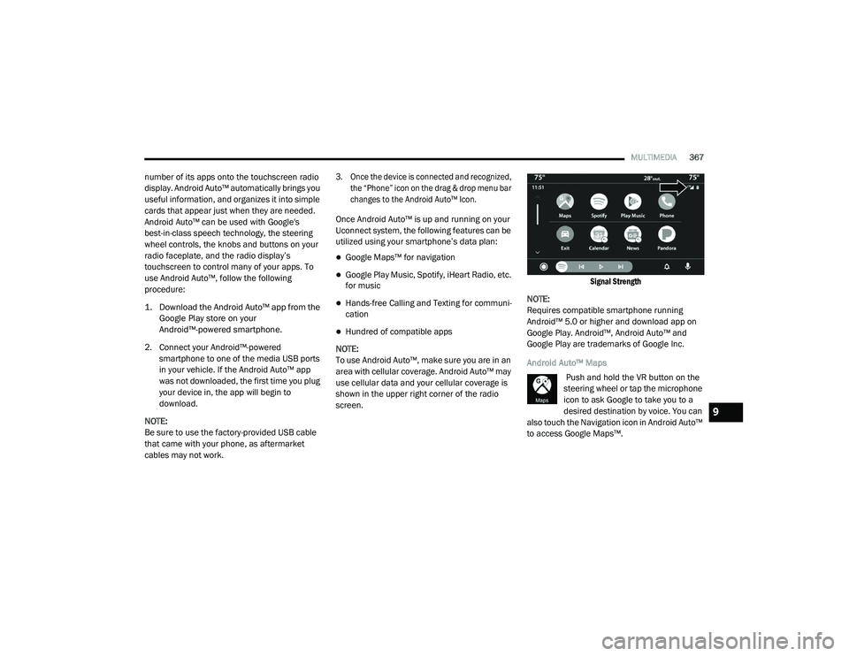
shown in the upper right corner of the radio
screen.
Signal Strength
NOTE:
Requires compatible smartphone running
Android™ 5.0 or higher and download app on
Google Play. Android™, Android Auto™ and
Google Play are trademarks of Google Inc.
Android Auto™ Maps Push and hold the VR button on the
steering wheel or tap the microphone
icon to ask Google to take you to a
desired destination by voice. You can
also touch the Navigation icon in Android Auto™
to access Google Maps™.
9
20_LD_OM_EN_USC_t.book Page 367