2020 CITROEN RELAY replace key
[x] Cancel search: replace keyPage 23 of 196

21
Access
2If your vehicle is so equipped, pressing this
control activates the alarm.
The central locking control indicator lamp comes
on and flashes.
Folding / Unfolding the
key
► Press this button to unfold / fold the
key.
If you do not press the button, you risk
damaging the mechanism.
Deadlocking
Pressing this button twice in succession
deadlocks the vehicle.
It is then impossible to open the doors from the
inside or the outside.
The direction indicators flash three times.
Never leave anyone inside the vehicle
when it is deadlocked.
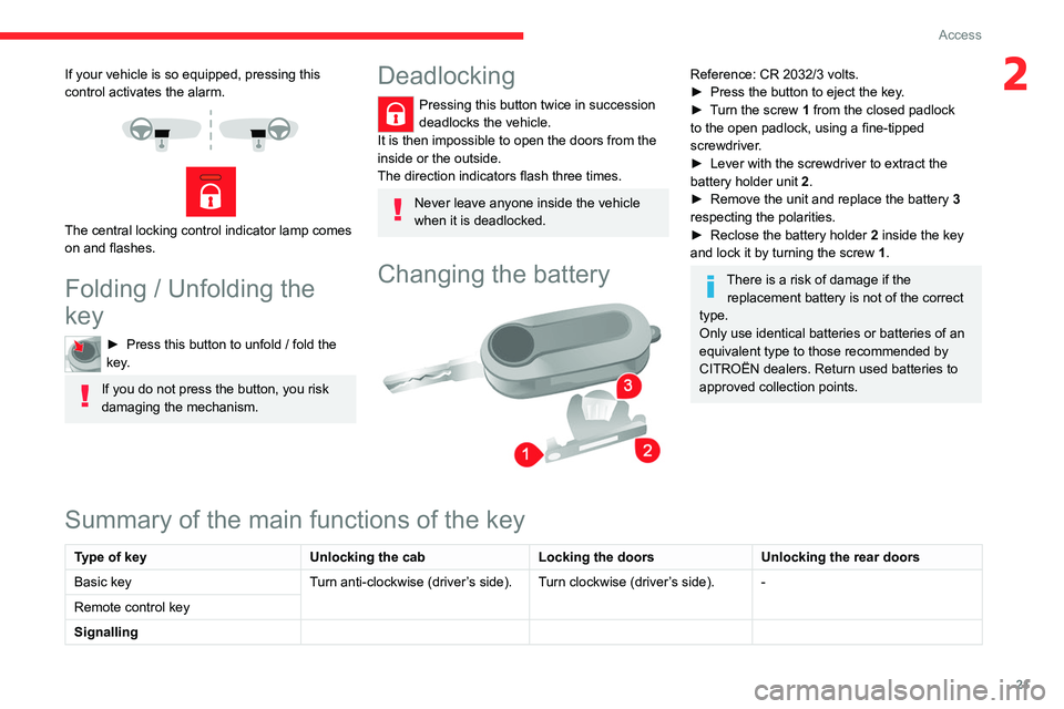
Changing the battery
Reference: CR 2032/3 volts.
► Press the button to eject the key.
► Turn the screw 1 from the closed padlock
to the open padlock, using a fine-tipped
screwdriver.
► Lever with the screwdriver to extract the
battery holder unit 2.
► Remove the unit and replace the battery 3
respecting the polarities.
► Reclose the battery holder 2 inside the key
and lock it by turning the screw 1.
There is a risk of damage if the
replacement battery is not of the correct
type.
Only use identical batteries or batteries of an
equivalent type to those recommended by
CITROËN dealers. Return used batteries to
approved collection points.
Summary of the main functions of the key
Type of key Unlocking the cabLocking the doorsUnlocking the rear doors
Basic key Turn anti-clockwise (driver’s side).Turn clockwise (driver’s side).-
Remote control key
Signalling
Page 92 of 196

90
Practical information
For other versions, the second button is
replaced by a fuse; contact a CITROËN
dealer or a qualified workshop.
Compatibility of fuels
Diesel fuels conforming to the EN590, EN16734
and EN16709 standards and containing up to
7%, 10%, 20% and 30% fatty acid methyl ester
respectively. The use of B20 or B30 fuels, even
occasionally, imposes special maintenance
conditions referred to as "Arduous conditions".
Paraffinic Diesel fuel conforming to the EN15940
standard.
The use of any other type of (bio) fuel (vegetable or animal oils, pure or diluted,
domestic fuel, etc.) is strictly prohibited (risk
of damage to the engine and fuel system).
The only Diesel fuel additives authorised for use are those that meet the B715000
standard.
Diesel at low temperature
At temperatures below 0 °C (+32 °F), the
formation of paraffins in summer-type Diesel
Fuel
The capacity of the tank is about 90 litres.
Fuel tanks of different capacities may be fitted,
60 and 120 litres, depending on the engine.
Low fuel level
When the low fuel tank level E (Empty) is
reached, this warning lamp comes on.
At this moment, you have approximately 10 or
12 litres left in the reserve, depending on the
capacity of your tank and the engine.
You must refuel as soon as possible to avoid
running out of fuel.
Refuelling
The fuel tank must be filled with the engine off.
► Open the fuel filler flap.
► Hold the black filler cap with one hand.
► With the other hand, insert the key and turn it
anti-clockwise.
► Remove the black filler cap and hang it on
the hook located on the inside of the filler flap.
A label inside the fuel filler flap indicates the type
of fuel to use.
Do not continue past the 3
rd cut-off of the nozzle.
This may cause malfunctions.
► After filling the fuel tank, lock the black filler
cap and close the filler flap.
With the Stop & Start system, never
refuel with the engine in STOP mode;
you must switch off the ignition using the key.
Fuel system cut off
In the event of an impact, a device automatically
cuts off the fuel supply to the engine and the
vehicle's power supply.
It triggers the hazard warning lamps and the
courtesy lamps, as well as the unlocking of the
doors.
After the impact and before restoring these power supplies, check that there
are no fuel leaks or sparks to avoid any risk of
fire.
► To restore the fuel supply, press the first
button, located on the front right-hand side.
► To then restore the power supply, press
the second button, located in the battery
compartment under the floor (Minibus).
Page 136 of 196

134
Technical data
In the engine compartment
A
Original paintwork
Colour
Code
Varnish
B
FOR TROUBLESHOOTING ONLY.
C
DANGER
AUTOMATIC ENGINE STARTING. REMOVE
THE IGNITION KEY WHEN THE BONNET IS
OPEN.
D
1 - WARNING
GENUINE LUBRICANTS AND FLUIDS
Engine oil Transmission
Radiator Brakes
Screenwash Power steering
CONSULT THE
MAINTENANCE
AND WARRANTY
GUIDE. PROTECT YOUR
EYES.
2 - SAFETY
The use of genuine replacement parts, fluids
and lubricants, as well as observing the servicing
schedules, guarantees the reliability and safety
of your vehicle over time, so maintaining it in its
original condition.
3 - DANGER
KEEP OUT
OF THE
REACH OF
CHILDREN. DO NOT
APPROACH
FLAMES. DO NOT
TOUCH.
DO NOT
REMOVE
THE CAP
WHEN THE
ENGINE IS
HOT. EXPLOSION.
CORROSIVE
LIQUID.
MAY START
AUTOMATICALLY EVEN
WITH THE ENGINE
SWITCHED OFF. DO NOT
OPEN GAS
UNDER HIGH
PRESSURE.
AUTOMATIC ENGINE
STARTING. REMOVE THE
IGNITION KEY WHEN THE
BONNET IS OPEN. HIGH
VOLTAGEIn the fuel filler flap
DANGER REMOVE SLOWLY.
FUEL VAPOURS MAY CAUSE INJURY.
Page 150 of 196

148
Special features
– Never work under a tipper body that is not
supported,
– Switch off the power supply to the electro-
hydraulic unit using the circuit breaker,
– Vehicle stationary, engine off.
For safety reasons, we very strongly
advise against doing anything under the
tipper body while it is being operated or while
it is being serviced.
Maintenance
Reservoir
Regularly check and top up the engine oil level.
Change the oil once a year. If the oil contains
water, change it.
Regularly check the condition of the hose and
ensure the hydraulic system is properly sealed.
Pump and motor
No servicing required. The rolling elements are
permanently lubricated and the bearings are
lubricated by the pumped oil.
Lubrication
The pins of the tipper truck and the ram do not
contain lubricant. Regularly lubricate the hinges
and the grab handles of the side boards as well
as the retaining hooks of the rear board.
Sub-frame and tipper truck
For maximum service life, you are advised to
maintain your tipper truck by regularly washing it
using a power washer.
Carry out any required paint touch-ups quickly to
prevent the spread of rust.
After 8 months of use, check the tightening torque of the connection
between the chassis and the underbody (in
accordance with the manufacturer's
bodybuilding recommendations).
Cleaning the slide valve
► Loosen cap 244A, taking care with the ball
and retrieving it.
► Using a wide screwdriver, unscrew the banjo
bolt/piston assembly.
► Check that the piston slides freely and
remove any foreign bodies. Use a magnet to
remove any metal filings.
► Refit the assembly and make sure that the
piston slides freely. Retain the ball with a little
grease on the cap for refitting.
► Bleed the hydraulic unit.
Bleeding the hydraulic unit
► Unscrew hexagonal cap 257.
► Loosen internal screw 587 by half a turn,
using a 6 mm hex key.
► Operate the unit for a few seconds by
pressing the raise button.
The tipper truck does not rise or rises very
slowly. When the oil exits through this opening,
the unit is bled.
► Retighten screw 587 and replace cap 257.
Check that the tipper truck lowers correctly.
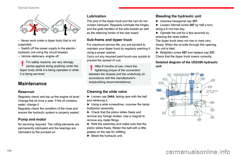
Detailed diagram of the UD2386 hydraulic
unit
Diagnostics
Symptoms ElectricHydraulic Verification/Check
The hydraulic unit does not work. XPower harness and unit relay.
X Control harness (control unit).
X Circuit-breaker.
Very noisy unit, rises slowly. XSuction strainer clogged or crushed at the bottom of the tank.
Very noisy new unit, rises quickly. XPump alignment, change the unit.
The ram lowers by itself. XLowering valve crushed or blocked.
The ram does not lower. XYes, check the slide valve and bleed.
Refer to the "Maintenance" section.
X No, check the coil and the electrical connections of the valve.
X No, replace the solenoid valve.
X No, check the alignment of the ram.
The unit works but its pressure does
not increase. X
Slide valve jammed if no solenoid valve on the unit.
Refer to the "Maintenance" section.
X Pressure relief device, setting, dirt.
X Pump seal out of service.
X Motor/pump coupling.
X Pump loose from its support.
The hydraulic unit does not work. XSolenoid valve blocked, replace it or retighten the nut behind the strainer .
The control unit does not work. XCheck connection and contacts.
Emulsion in the tank. XIncorrectly positioned return pipe.
X Insufficient oil level.