2020 CHRYSLER 300 wheel torque
[x] Cancel search: wheel torquePage 8 of 328

6
DEALER SERVICE .............................................. 239 Engine Oil .................................................. 240Engine Oil Filter ..........................................241Engine Air Cleaner Filter ...........................241
Air Conditioner Maintenance ...................242Accessory Drive Belt Inspection................243Body Lubrication ........................................244
Windshield Wiper Blades ..........................244
Exhaust System .........................................246
Cooling System .........................................247
Brake System ............................................250
Automatic Transmission ...........................251
All Wheel Drive (AWD) — If Equipped .......253
Rear Axle ....................................................253
RAISING THE VEHICLE ...................................... 253
TIRES ................................................................... 253
Tire Safety Information .............................253Tires — General Information .....................261Tire Types ...................................................265
Spare Tires — If Equipped .........................266
Wheel And Wheel Trim Care ....................268
Tire Chains and Traction Devices .............269
Tire Rotation Recommendations .............270 DEPARTMENT OF TRANSPORTATION
UNIFORM TIRE QUALITY GRADES .................. 270
Treadwear .................................................. 270
Traction Grades ......................................... 271
Temperature Grades ................................. 271
VEHICLE STORAGE .............................................271
BODYWORK ........................................................ 272
Protection From Atmospheric Agents....... 272
Body And Underbody Maintenance .......... 272Preserving The Bodywork .......................... 272
INTERIORS ......................................................... 273
Seats And Fabric Parts .............................. 273
Plastic And Coated Parts ........................... 274
Leather Parts ............................................. 274
Glass Surfaces .......................................... 274
TECHNICAL SPECIFICATIONS
IDENTIFICATION DATA .......................................275Vehicle Identification Number .................. 275
BRAKE SYSTEM ................................................. 275
WHEEL AND TIRE TORQUE
SPECIFICATIONS ................................................ 275
Torque Specifications ................................ 275 FUEL REQUIREMENTS ...................................... 276
3.6L Engine ................................................ 276
5.7L Engine ................................................ 276
Reformulated Gasoline ............................ 277Materials Added To Fuel ........................... 277
Gasoline/Oxygenate Blends ..................... 277
Do Not Use E-85 In Non-Flex Fuel
Vehicles ...................................................... 278 CNG And LP Fuel System Modifications .. 278MMT In Gasoline........................................ 278
Fuel System Cautions................................ 279
Carbon Monoxide Warnings...................... 279
FLUID CAPACITIES ............................................ 280
FLUIDS AND LUBRICANTS ............................... 281
Engine ........................................................ 281
Chassis ...................................................... 283MULTIMEDIA
UCONNECT SYSTEMS ....................................... 284
CYBERSECURITY ............................................... 284
UCONNECT SETTINGS ...................................... 285 Customer Programmable Features —
Uconnect 4C/4C NAV Settings ................ 285
20_LX_OM_EN_USC_t.book Page 6
Page 92 of 328

90GETTING TO KNOW YOUR INSTRUMENT PANEL
occur for a variety of reasons, including the
installation of replacement or alternate tires or
wheels on the vehicle that prevent the TPMS
from functioning properly. Always check the
TPMS malfunction warning light after replacing
one or more tires or wheels on your vehicle to
ensure that the replacement or alternate tires
and wheels allow the TPMS to continue to
function properly.Low Fuel Warning Light
When the fuel level reaches
approximately 1.9 gal (7.13 L), this
light will turn on and a single chime
will sound.
Anti-Lock Brake (ABS) Warning Light
This warning light monitors the
Anti-Lock Brake System (ABS). The
light will turn on when the ignition is
placed in the ON/RUN or ACC/ON/
RUN position and may stay on for as long as four
seconds.
If the ABS light remains on or turns on while
driving, then the Anti-Lock portion of the brake
system is not functioning and service is
required as soon as possible. However, the
conventional brake system will continue to
operate normally, assuming the Brake Warning
Light is not also on.
If the ABS light does not turn on when the
ignition is placed in the ON/RUN or ACC/ON/
RUN position, have the brake system inspected
by an authorized dealer.
Service Forward Collision Warning (FCW)
Light — If Equipped
This warning light will illuminate to
indicate a fault in the Forward
Collision Warning System. Contact an
authorized dealer for service.
Refer to "Forward Collision Warning (FCW)" in
"Safety" for further information.
Service AWD Warning Light — If Equipped
This warning light will turn on to
indicate the All Wheel Drive (AWD)
system is not functioning properly and
that service is required. Contact an
authorized dealer.
LaneSense Warning Light — If Equipped
The LaneSense system provides the
driver with visual and steering torque
warnings when the vehicle starts to
drift out of its lane unintentionally
without the use of a turn signal.
When the LaneSense system senses a lane
drift situation, the LaneSense indicator
changes from solid green to solid yellow.
CAUTION!
The TPMS has been optimized for the original
equipment tires and wheels. TPMS pressures
and warning have been established for the
tire size equipped on your vehicle.
Undesirable system operation or sensor
damage may result when using replacement
equipment that is not of the same size, type,
and/or style. Aftermarket wheels can cause
sensor damage. Using aftermarket tire
sealants may cause the Tire Pressure
Monitoring System (TPMS) sensor to become
inoperable. After using an aftermarket tire
sealant it is recommended that you take your
vehicle to an authorized dealer to have your
sensor function checked.
20_LX_OM_EN_USC_t.book Page 90
Page 99 of 328

SAFETY97
Electronic Brake Force Distribution (EBD)
The Electronic Brake Force Distribution (EBD)
function manages the distribution of the
braking torque between the front and rear axles
by limiting braking pressure to the rear axle.
This is done to prevent overslip of the rear
wheels to avoid vehicle instability, and to
prevent the rear axle from entering the
Anti-Lock Brake System (ABS) before the front
axle.
Electronic Roll Mitigation (ERM)
The Electronic Roll Mitigation (ERM) system
anticipates the potential for wheel lift by
monitoring the driver’s steering wheel input and
the speed of the vehicle. When ERM determines
that the rate of change of the steering wheel
angle and vehicle’s speed are sufficient to
potentially cause wheel lift, it then applies the
appropriate brake and may also reduce engine
power to lessen the chance that wheel lift will
occur. ERM can only reduce the chance of
wheel lift occurring during severe or evasive
driving maneuvers; it cannot prevent wheel lift
due to other factors, such as road conditions,
leaving the roadway, or striking objects or other
vehicles. NOTE:
ERM is disabled anytime the ESC is in “Full Off”
mode (if equipped). Refer to “Electronic Stability
Control (ESC)” in this section for a complete
explanation of the available ESC modes.
Electronic Stability Control (ESC)
The Electronic Stability Control (ESC) system
enhances directional control and stability of the
vehicle under various driving conditions. ESC
corrects for oversteering or understeering of the
vehicle by applying the brake of the appropriate
wheel(s) to assist in counteracting the oversteer
or understeer condition. Engine power may also be reduced to help the vehicle maintain the
desired path.
ESC uses sensors in the vehicle to determine
the vehicle path intended by the driver and
compares it to the actual path of the vehicle.
When the actual path does not match the
intended path, ESC applies the brake of the
appropriate wheel to assist in counteracting the
oversteer or understeer condition.
Oversteer — when the vehicle is turning more
than appropriate for the steering wheel posi
-
tion.
Understeer — when the vehicle is turning less
than appropriate for the steering wheel posi -
tion.
The “ESC Activation/Malfunction Indicator
Light” located in the instrument cluster will start
to flash as soon as the ESC system becomes
active. The “ESC Activation/Malfunction
Indicator Light” also flashes when the TCS is
active. If the “ESC Activation/Malfunction
Indicator Light” begins to flash during
acceleration, ease up on the accelerator and
apply as little throttle as possible. Be sure to
adapt your speed and driving to the prevailing
road conditions.
WARNING!
Many factors, such as vehicle loading, road
conditions and driving conditions, influence
the chance that wheel lift or rollover may
occur. ERM cannot prevent all wheel lift or roll
overs, especially those that involve leaving
the roadway or striking objects or other
vehicles. The capabilities of an
ERM-equipped vehicle must never be
exploited in a reckless or dangerous manner
which could jeopardize the user's safety or
the safety of others.
4
20_LX_OM_EN_USC_t.book Page 97
Page 104 of 328

102SAFETY
Traction Control System (TCS)
The Traction Control System (TCS) monitors the
amount of wheel spin of each of the driven
wheels. If wheel spin is detected, the TCS may
apply brake pressure to the spinning wheel(s)
and/or reduce engine power to provide
enhanced acceleration and stability. A feature
of the TCS, Brake Limited Differential (BLD),
functions similar to a limited slip differential
and controls the wheel spin across a driven
axle. If one wheel on a driven axle is spinning
faster than the other, the system will apply the
brake of the spinning wheel. This will allow more
engine torque to be applied to the wheel that is
not spinning. BLD may remain enabled even if
TCS and ESC are in a reduced mode.AUXILIARY DRIVING SYSTEMS
BLIND SPOT MONITORING (BS M) — IF
E
QUIPPED
The Blind Spot Monitoring (BSM) system uses
two radar sensors, located inside the rear
bumper fascia, to detect highway licensable
vehicles (automobiles, trucks, motorcycles,
etc.) that enter the blind spot zones from the
rear/front/side of the vehicle.
Rear Detection Zones
When the vehicle is started, the BSM warning
light will momentarily illuminate in both outside
rearview mirrors to let the driver know that the
system is operational. The BSM system sensors
operate when the vehicle is in any forward gear
or REVERSE.
BSM Warning Light
The BSM detection zone covers approximately one
lane width on both sides of the vehicle 12 ft
(3.8 m). The zone length starts at the outside rear
view mirror and extends approximately 10 ft (3 m)
beyond the rear bumper of the vehicle. The BSM
system monitors the detection zones on both
sides of the vehicle when the vehicle speed
reaches approximately 6 mph (10 km/h) or higher
and will alert the driver of vehicles in these areas.
NOTE:
The BSM system DOES NOT alert the driver
about rapidly approaching vehicles that are
outside the detection zones.
20_LX_OM_EN_USC_t.book Page 102
Page 186 of 328

184STARTING AND OPERATING
haptic warning in the form of torque applied to
the steering wheel to prompt the driver to
remain within the lane boundaries. If the driver
continues to drift out of the lane, the LaneSense
system provides a visual warning through the
instrument cluster display to prompt the driver
to remain within the lane boundaries.
The driver may manually override the haptic
warning by applying torque into the steering
wheel at any time.
When only a single lane marking is detected
and the driver drifts across the lane marking (no
turn signal applied), the LaneSense system
provides visual warnings through the
instrument cluster display to prompt the driver
to remain within the lane. When only a single
lane marking is detected, a haptic (torque)
warning will not be provided.
NOTE:
When operating conditions have been met, the
LaneSense system will monitor if the driver’s
hands are on the steering wheel and provides
an audible warning to the driver when the
driver’s hands are not detected on the steering
wheel. The system will cancel if the driver does
not return their hands to the wheel.TURNING LANESENSE ON OR OFF
The default status of LaneSense is off. The LED
in the LaneSense button will be illuminated
when the system is deactivated.
The LaneSense button is located on the center
stack below the Uconnect display.
To turn the LaneSense system on,
push the LaneSense button (LED
turns off). A “LaneSense On”
message is shown in the instrument
cluster display.
To turn the LaneSense system off, push the
LaneSense button once (LED turns on).
NOTE:
The LaneSense system will retain the last
system state, on or off, from the last ignition
cycle when the ignition is changed to the
ON/RUN position.
LANESENSE WARNING MESSAGE
The LaneSense system will indicate the current
lane drift condition through the instrument
cluster display.
Premium Instrument Cluster Display Screen
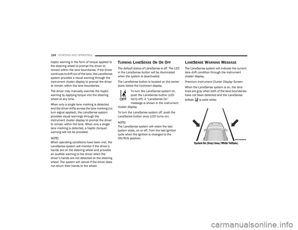
When the LaneSense system is on, the lane
lines are gray when both of the lane boundaries
have not been detected and the LaneSense
telltale is solid white.
System On (Gray Lines/White Telltale)
20_LX_OM_EN_USC_t.book Page 184
Page 187 of 328

STARTING AND OPERATING185
Left Lane Departure — Only Left Lane Detected
When the LaneSense system is on, the Lane-
Sense telltale is solid white when only the
left lane marking has been detected and the
system is ready to provide visual warnings in
the instrument cluster display if an uninten -
tional lane departure occurs.
When the LaneSense system senses the lane
has been approached and is in a lane depar -
ture situation, the left thick lane line flashes
yellow (on/off), the left thin line remains solid
yellow and the LaneSense telltale
changes from solid white to flashing yellow.
Lane Approached (Flashing Yellow Thick Line, Solid Yellow Thin Line/Flashing Yellow Telltale)
NOTE:
The LaneSense system operates with similar
behavior for a right lane departure when only
the right lane marking has been detected.
Left Lane Departure — Both Lanes Detected
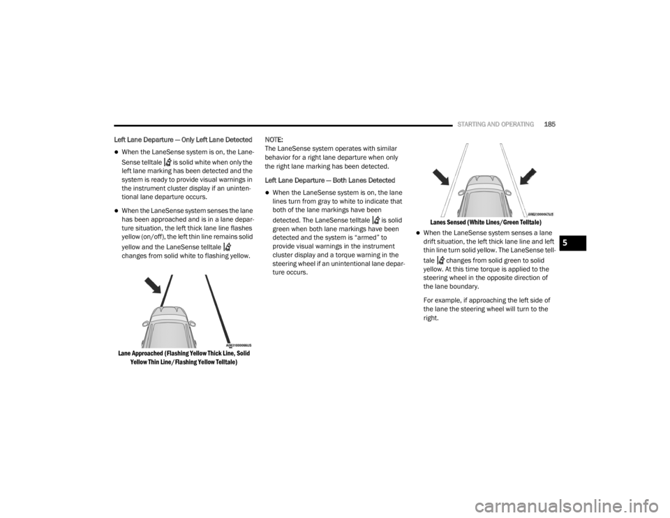
When the LaneSense system is on, the lane
lines turn from gray to white to indicate that
both of the lane markings have been
detected. The LaneSense telltale is solid
green when both lane markings have been
detected and the system is “armed” to
provide visual warnings in the instrument
cluster display and a torque warning in the
steering wheel if an unintentional lane depar
-
ture occurs.
Lanes Sensed (White Lines/Green Telltale)
When the LaneSense system senses a lane
drift situation, the left thick lane line and left
thin line turn solid yellow. The LaneSense tell
-
tale changes from solid green to solid
yellow. At this time torque is applied to the
steering wheel in the opposite direction of
the lane boundary.
For example, if approaching the left side of
the lane the steering wheel will turn to the
right.
5
20_LX_OM_EN_USC_t.book Page 185
Page 188 of 328

186STARTING AND OPERATING
Lane Sensed (Solid Yellow Lines/Solid Yellow Telltale)
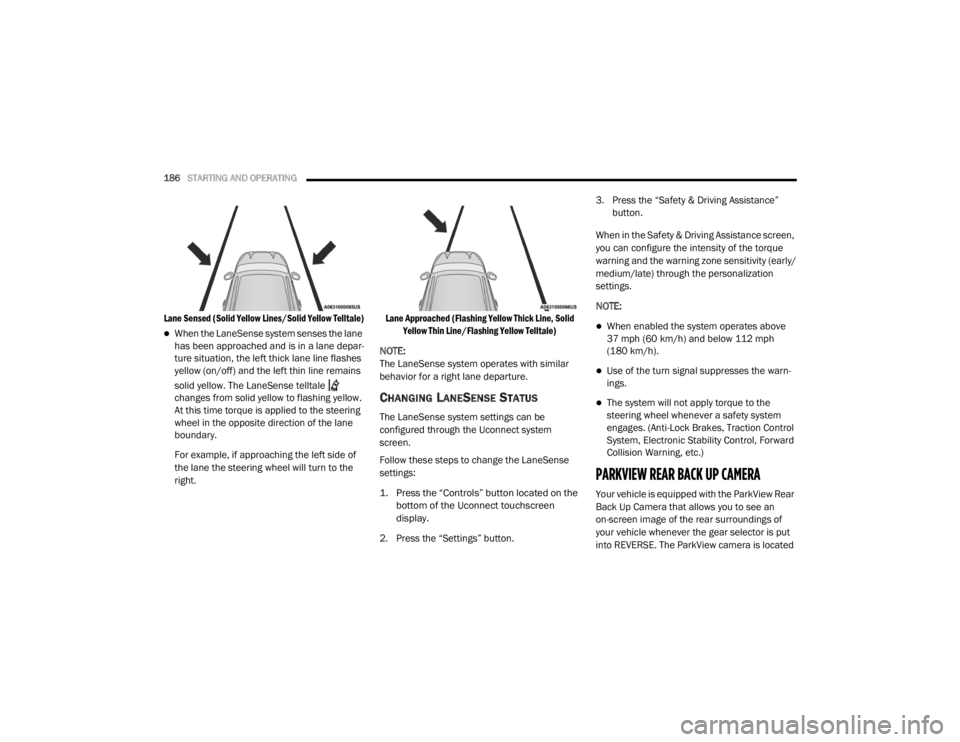
When the LaneSense system senses the lane
has been approached and is in a lane depar -
ture situation, the left thick lane line flashes
yellow (on/off) and the left thin line remains
solid yellow. The LaneSense telltale
changes from solid yellow to flashing yellow.
At this time torque is applied to the steering
wheel in the opposite direction of the lane
boundary.
For example, if approaching the left side of
the lane the steering wheel will turn to the
right.
Lane Approached (Flashing Yellow Thick Line, Solid
Yellow Thin Line/Flashing Yellow Telltale)
NOTE:
The LaneSense system operates with similar
behavior for a right lane departure.
CHANGING LANESENSE STATUS
The LaneSense system settings can be
configured through the Uconnect system
screen.
Follow these steps to change the LaneSense
settings:
1. Press the “Controls” button located on the bottom of the Uconnect touchscreen
display.
2. Press the “Settings” button. 3. Press the “Safety & Driving Assistance”
button.
When in the Safety & Driving Assistance screen,
you can configure the intensity of the torque
warning and the warning zone sensitivity (early/
medium/late) through the personalization
settings.
NOTE:
When enabled the system operates above
37 mph (60 km/h) and below 112 mph (180 km/h).
Use of the turn signal suppresses the warn -
ings.
The system will not apply torque to the
steering wheel whenever a safety system
engages. (Anti-Lock Brakes, Traction Control
System, Electronic Stability Control, Forward
Collision Warning, etc.)
PARKVIEW REAR BACK UP CAMERA
Your vehicle is equipped with the ParkView Rear
Back Up Camera that allows you to see an
on-screen image of the rear surroundings of
your vehicle whenever the gear selector is put
into REVERSE. The ParkView camera is located
20_LX_OM_EN_USC_t.book Page 186
Page 223 of 328

IN CASE OF EMERGENCY221
6. Remove the lug nuts and tire.
7. Mount the spare tire.
Mounting Spare Tire
NOTE:
For vehicles so equipped, do not attempt to
install a center cap or wheel cover on the
compact spare.
Refer to “Compact Spare Tire” and to
“Limited-Use Spare” under “Tires” in
“Servicing And Maintenance” for additional
warnings, cautions, and information about
the spare tire, its use, and operation.
8. Install the lug nuts with the cone shaped end of the lug nut toward the wheel. Lightly
tighten the lug nuts.
9. Lower the vehicle to the ground by turning the jack handle counterclockwise. 10. Finish tightening the lug nuts. Push down on
the wrench while at the end of the handle
for increased leverage. Tighten the lug nuts
in a star pattern until each nut has been
tightened twice. For the correct lug nut
torque, refer to “Wheel And Tire Torque
Specifications” in “Technical Specifi -
cations”. If in doubt about the correct
tightness, have them checked with a torque
wrench by an authorized dealer or at a
service station.
11. Stow the jack, tools and flat tire. Make sure the base of the jack faces the front of the
vehicle before tightening down the fastener.
WARNING!
Raising the vehicle higher than necessary can
make the vehicle less stable. It could slip off
the jack and hurt someone near it. Raise the
vehicle only enough to remove the tire.
CAUTION!
Be sure to mount the spare tire with the valve
stem facing outward. The vehicle could be
damaged if the spare tire is mounted
incorrectly.
WARNING!
To avoid the risk of forcing the vehicle off the
jack, do not tighten the wheel nuts fully until
the vehicle has been lowered. Failure to
follow this warning may result in serious
injury.WARNING!
A loose tire or jack thrown forward in a
collision or hard stop could endanger the
occupants of the vehicle. Always stow the jack
parts and the spare tire in the places
provided. Have the deflated (flat) tire repaired
or replaced immediately.
6
20_LX_OM_EN_USC_t.book Page 221