Page 49 of 122

Instrument and control functions
3-35
3
TIP
Make sure that the slide plate
holders are aligned with the match
marks at the same height on both
sides of the windshield.
Make sure that the projection on
each slide plate holder fits into the
corresponding hole in the slide
plate.
4. Tighten the adjusting knobs.
EAU55425
Adjustin g the front an d rear
suspension
This model is equipped with an elec-
tronically adjustable suspension sys-
tem. The preload of the rear shock
absorber and the damping forces of
both the front fork and rear shock ab-
sorber can be adjusted.
WARNING
EWA12423
Be sure to stop the vehicle before
makin g any settin g chan ges to the
multi-function meter unit. Chang ing
settin gs while ri din g can d istract the
operator an d increase the risk of an
acci dent.
Preloa d
When riding with luggage or a passen-
ger, use the preload adjusting function
to adjust the suspension system to
match the load. There are 4 preload
settings.
TIP
The preload adjusting function will
appear only when the engine is
running.
Changing the preload setting will
also adjust the front and rear sus-
pension damping forces accord-
ingly. (See page 3-37.)
About cold temperature opera-
tion:
• When using the preload adjust- ing function, there should be no
weight on the vehicle.
• When using the preload adjust- ing function at ambient temper-
atures near or below 0 °C (32
°F), the suspension system
warning light may come on.
1. Match mark
2. Slide plate
2
1
UBP9E1E0.book Page 35 Friday, September 7, 2018 10:01 AM
Page 50 of 122

Instrument and control functions
3-36
3 • The suspension will still operate
as normal, only the preload ad-
justing function cannot be used.
• To reset the suspension system warning light, wait approximate-
ly 6 minutes and then turn the
main switch off or immediately
turn the main switch off and
then wait 6 minutes.
• If the suspension system warn- ing light remains on, have a
Yamaha dealer check the vehi- cle.
To adjust the preload
1. Turn the main switch on, start the engine, and then shift the trans-
mission into neutral.
2. Push the menu switch to switch the function display to the preload
adjusting function. 3. Use the select switch to select the
desired preload setting pictogram.
Select the suitable setting from
the following 4 pictograms ac-
cording to your load condition.
While the preload is being adjust-
ed, the information display will
show a group of dots moving in a
circle. Once the selected picto-
gram returns, the preload adjust-
ment is complete.
1. Function display
2. Preload adjusting function
3. Preload setting pictogram
GEAR
N
1
3
2
1. Menu switch “MENU”
2. Select switch “ / ”
1. Solo riding
2. Solo riding and luggage
3. Passenger riding
4. Passenger riding and luggage
1
2
12
34
UBP9E1E0.book Page 36 Friday, September 7, 2018 10:01 AM
Page 51 of 122

Instrument and control functions
3-37
3
While the preload is being adjusted,
the information display may change as
follows.
If the main switch is turned off or
the engine is stopped while the
preload is being set, the following
preload setting pictogram will
flash to alert you that the current
preload setting does not match
the pictogram. If this occurs, ad-
just the preload again.
If the vehicle starts moving, the
following preload setting picto-
gram will flash to alert you that the
current preload setting does not
match the pictogram. If this oc-
curs, stop the vehicle and adjust
the preload again.
If the preload is adjusted repeat-
edly, the preload setting picto-
gram will flash 4 times and the
preload cannot be adjusted. Wait
approximately 6 minutes for the
preload adjusting function motor
to cool down, and then try adjust-
ing the preload again.
Dampin g force
Within each preload setting there are 3
damping force settings: “HARD”
(hard), “STD” (standard) and “SOFT”
(soft). When the preload setting is
changed, the damping force settings
will change accordingly. (The electron-
ically adjustable suspension system
will automatically adjust to the damp-
ing force settings last set for that pre-
load setting.) To further finely adjust
the damping force, each damping for-
ce setting can be set to 7 different lev-
els.
GEAR
N
GEAR
N
GEAR
N
GEAR
N
GEAR
1
HARD+3
GEAR
N
GEAR
N
GEAR
N
UBP9E1E0.book Page 37 Friday, September 7, 2018 10:01 AM
Page 52 of 122

Instrument and control functions
3-38
3
TIP
If the preload setting was not complet-
ed correctly:
The damping force setting and
setting level will flash 4 times and
cannot be adjusted if you try to
adjust them while the vehicle is
stopped.
The preload setting pictogram will
flash and the damping force can-
not be adjusted if you try to adjust
it while the vehicle is moving.
Be sure that the preload has been set
correctly before adjusting the damping
force.
To adjust the damping force and
damping force setting level
1. Turn the main switch on.
2. Push the menu switch to switch the function display to the damp-
ing force adjusting function. 3. Use the select switch to select
“HARD”, “STD” or “SOFT”.
4. Push the menu switch.
5. Use the select switch to select the desired level for the damping for-
ce setting.
1. Damping force setting
2. Damping force setting level
GEAR
N
HARD+3
2
1
1. Function display
2. Damping force adjusting function
1. Damping force setting
1. Damping force setting level
GEAR
N
STD0
1
2
GEAR
N
HARD 01
GEAR
N
HARD
+31
UBP9E1E0.book Page 38 Friday, September 7, 2018 10:01 AM
Page 53 of 122
.
“+3” is the hardest level and “–3” is the
softest level.
6.")
Instrument and control functions
3-39
3
TIP
The damping force setting can be set to
7 levels (+3, +2, +1, 0, –1, –2 and –3).
“+3” is the hardest level and “–3” is the
softest level.
6. Push the menu switch.
If the vehicle moves while you are ad-
justing the damping force, the informa-
tion display will change to the display
mode.
WARNING
EWA16421
The rear shock a bsor ber assem bly
contains hi ghly pressurize d nitro gen
g as. Rea d an d un derstan d the fol-
lowin g information before han dlin g
the shock a bsor ber assem bly.
Do not tamper with or attempt
to open the cylind er assembly.
Do not su bject the shock a b-
sor ber assem bly to an open
flame or other hi gh heat source.
This may cause the unit to ex-
plo de due to excessive g as
pressure.
Do not deform or damag e the
cylin der in any way. Cylin der
d amag e will result in poor
d ampin g performance.
Do not dispose of a dama ged or
worn-out shock a bsor ber
as-
sem bly yourself. Take the shock
a b sor ber assem bly to a Yamaha
d ealer for any service.
1. Damping force adjusting function
2. Damping force setting
3. Preload setting pictogram
GEAR
N
HARD
+3
GEAR
1
HARD+3
1
2
3
UBP9E1E0.book Page 39 Friday, September 7, 2018 10:01 AM
Page 54 of 122
Instrument and control functions
3-40
3
EAU49705
Carriers
This motorcycle is equipped with a
standard carrier, and with an additional
carrier located under the passenger
seat. This additional carrier extends the
loading surface and the loading capac-
ity of the standard carrier.
To use the additional carrier, consult a
Yamaha dealer.
Stan dar d carrier
A dditional carrier
WARNING
EWA15484
Do not exceed the maximum
loa d of 204 k g (450 l b) for the ve-
hicle.
Do not sit on an d never ri de with
a passen ger on the stan dar d or
a dditional carrier.
Do not exceed the standar d car-
rier capacity of 5.0 k g (11 l b).
Do not exceed the additional
carrier capacity of 5.0 kg (11 lb).
NOTICE
ECA16822
Do not lift the vehicle b y either carri-
er.
1. Standard carrier
1. Additional carrier
1
1
UBP9E1E0.book Page 40 Friday, September 7, 2018 10:01 AM
Page 55 of 122
Instrument and control functions
3-41
3
EAU84680
Lugg ag e strap hol ders
Use the indicated strap points to se-
cure luggage ties to the vehicle.
EAU49454
Auxiliary DC jack
A 12-V accessory connected to the
auxiliary DC jack can be used when the
main switch is on.
NOTICE
ECA15432
The accessory connected to the
auxiliary DC jack shoul d not b e used
with the en gine turne d off, an d the
loa d must never excee d 30 W (2.5 A),
otherwise the fuse may blow or the
b attery may dischar ge.
To use the auxiliary DC jack
1. Turn the main switch off.
2. Remove the auxiliary DC jack cap.
3. Turn the accessory off.
4. Insert the accessory plug into the auxiliary DC jack.
1. Luggage strap holder
1
1. Auxiliary DC jack cap
1. Auxiliary DC jack
1
1
UBP9E1E0.book Page 41 Friday, September 7, 2018 10:01 AM
Page 56 of 122

6. Turn the accessory on.
WARNING
EWA14361
To prevent electrical shock or short-
circuitin g,")
Instrument and control functions
3-42
3 5. Turn the main switch on, and start
the engine. (See page 5-2.)
6. Turn the accessory on.
WARNING
EWA14361
To prevent electrical shock or short-
circuitin g, make sure that the cap is
installe d when the auxiliary DC jack
is not b eing use d.
EAU15306
Si destan d
The sidestand is located on the left
side of the frame. Raise the sidestand
or lower it with your foot while holding
the vehicle upright.
TIP
The built-in sidestand switch is part of
the ignition circuit cut-off system,
which cuts the ignition in certain situa-
tions. (See the following section for an
explanation of the ignition circuit cut-
off system.)
WARNING
EWA10242
The vehicle must not be ri dden with
the si destan d d own, or if the si de-
stan d cannot b e properly move d up
(or does not stay up), otherwise the
si destan d coul d contact the groun d
an d d istract the operator, resultin g
in a possi ble loss of control.
Yamaha’s ig nition circuit cut-off
system has been desi gne d to assist
the operator in fulfillin g the respon-
si bility of raisin g the si destan d b e-
fore startin g off. Therefore, check
this system re gularly an d have a
Yamaha dealer repair it if it does not
function properly.
UBP9E1E0.book Page 42 Friday, September 7, 2018 10:01 AM
 1
1 2
2 3
3 4
4 5
5 6
6 7
7 8
8 9
9 10
10 11
11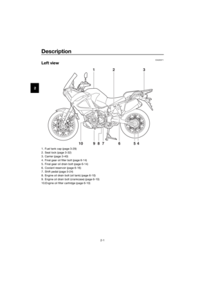 12
12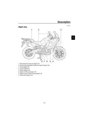 13
13 14
14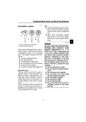 15
15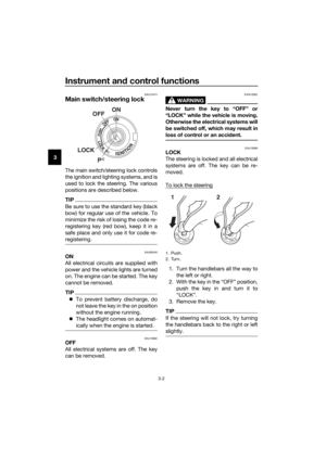 16
16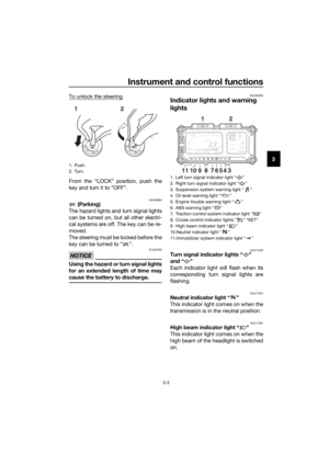 17
17 18
18 19
19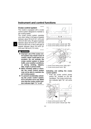 20
20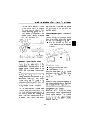 21
21 22
22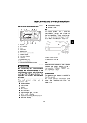 23
23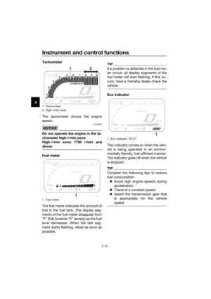 24
24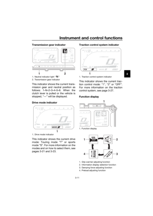 25
25 26
26 27
27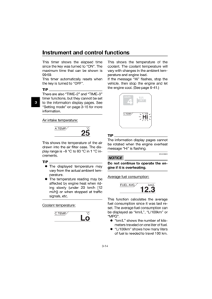 28
28 29
29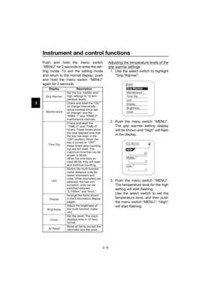 30
30 31
31 32
32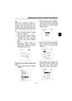 33
33 34
34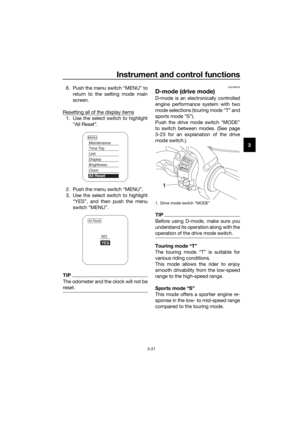 35
35 36
36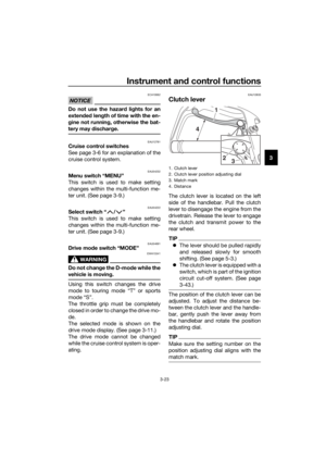 37
37 38
38 39
39 40
40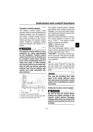 41
41 42
42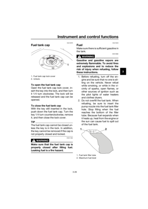 43
43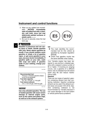 44
44 45
45 46
46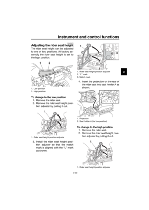 47
47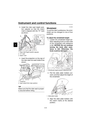 48
48 49
49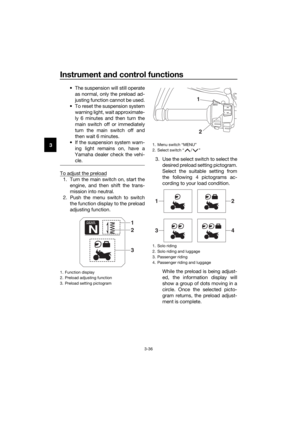 50
50 51
51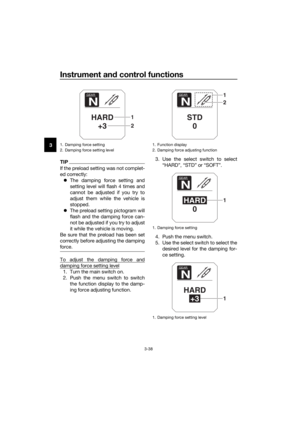 52
52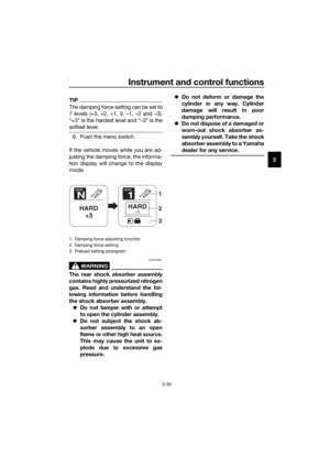 53
53 54
54 55
55 56
56 57
57 58
58 59
59 60
60 61
61 62
62 63
63 64
64 65
65 66
66 67
67 68
68 69
69 70
70 71
71 72
72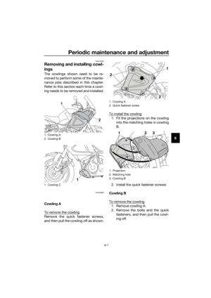 73
73 74
74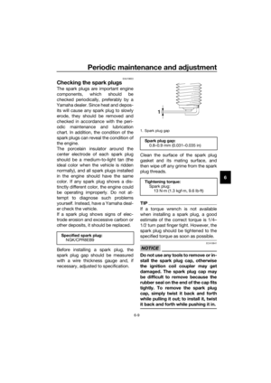 75
75 76
76 77
77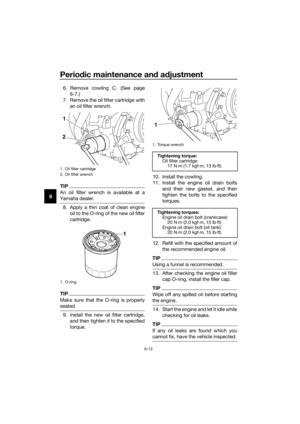 78
78 79
79 80
80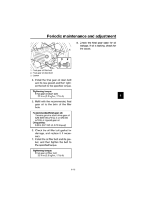 81
81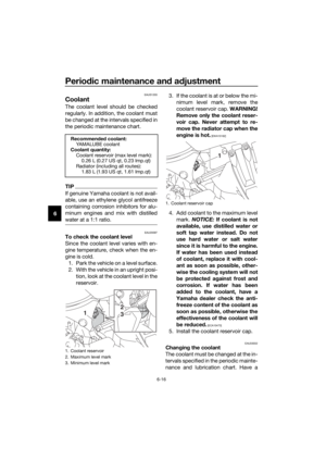 82
82 83
83 84
84 85
85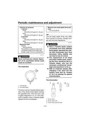 86
86 87
87 88
88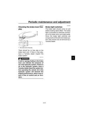 89
89 90
90 91
91 92
92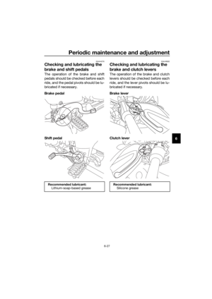 93
93 94
94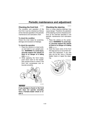 95
95 96
96 97
97 98
98 99
99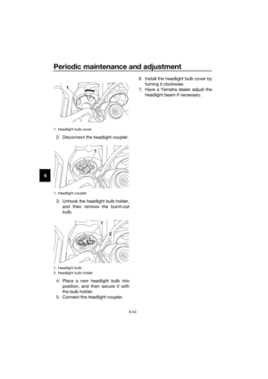 100
100 101
101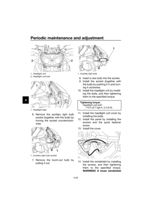 102
102 103
103 104
104 105
105 106
106 107
107 108
108 109
109 110
110 111
111 112
112 113
113 114
114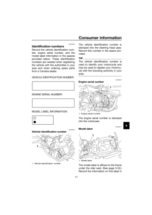 115
115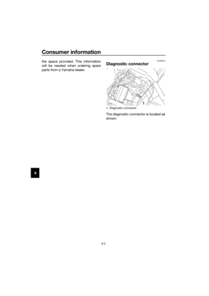 116
116 117
117 118
118 119
119 120
120 121
121
