2019 VOLKSWAGEN TRANSPORTER length
[x] Cancel search: lengthPage 193 of 486
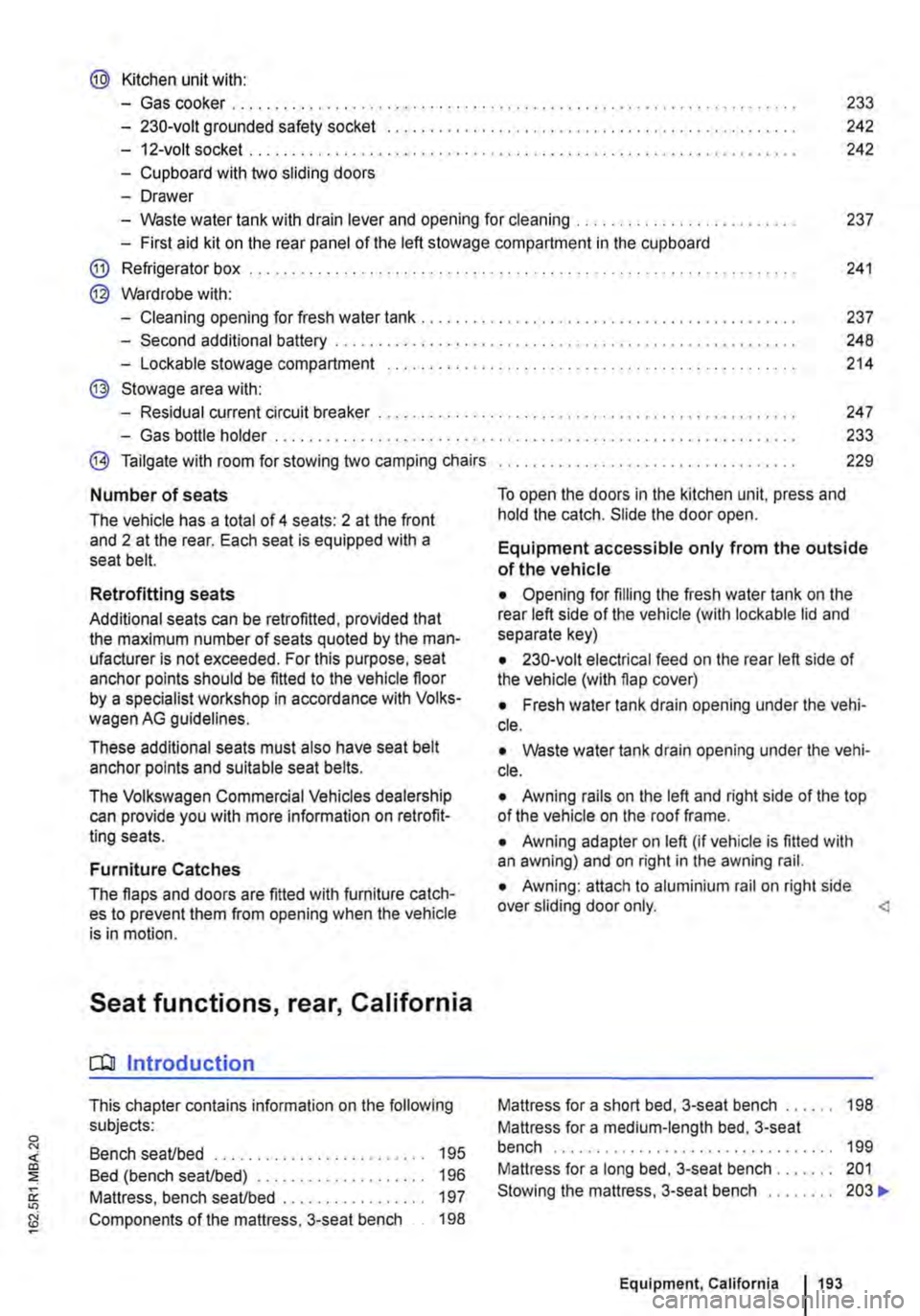
@ Kitchen unit with:
-Gas cooker ................................... . 233
242
242
-230-volt grounded safety socket ................. .
-12-volt socket .............................•..................................
-Cupboard with two sliding doors
-Drawer
-Waste water tank with drain lever and opening for cleaning ...... . 237
-First aid kit on the rear panel of the left stowage compartment in the cupboard
@ Refrigerator box ...
@ Wardrobe with:
241
-Cleaning opening for fresh water tank . . . . . . . . . . . . . . . . . . . . . . . . . . . . . . . . . . . . . . . 237
-Second additional battery . . . . . ........ , . . . . . . . . . . . . . . . . . . . . . . . . . . 248
-Lockable stowage compartment . . . . . . . . . . . . . . . . . . . . . . . . . . . . . . . . . . . . . . . . . . . . . . . . 214
@ Stowage area with:
-Residual current circuit breaker ............... , ...... . 247
233
229
-Gas bottle holder .................. .
® Tailgate with room for stowing two camping chairs
Number of seats
The vehicle has a total of 4 seats: 2 at the front and 2 at the rear. Each seat is equipped with a seat belt.
Retrofitting seats
Additional seats can be retrofitted, provided that the maximum number of seats quoted by the man-ufacturer is not exceeded. For this purpose, seat anchor points should be fitted to the vehicle floor by a specialist workshop in accordance with Volks-wagen AG guidelines.
These additional seats must also have seat belt anchor points and suitable seat belts.
The Volkswagen Commercial Vehicles dealership can provide you with more information on retrofit-ting seats.
Furniture Catches
The flaps and doors are fitted with furniture catch-es to prevent them from opening when the vehicle is in motion.
Seat functions, rear, California
ClJ Introduction
This chapter contains information on the following subjects:
Bench seat/bed . . . . . . . . . . . . . . . . . . . . • • . . . 195
Bed (bench seat/bed) . . . . . . . . . . . 196 Mattress, bench seat/bed . . . . . . . . . . . . . . . . . 197
Components of the mattress, 3-seat bench . . 198
To open the doors in the kitchen unit, press and hold the catch. Slide the door open.
Equipment accessible only from the outside of the vehicle
• Opening for filling the fresh water tank on the rear left side of the vehicle (with lockable lid and separate key)
• 230-volt electrical feed on the rear left side of the vehicle (with flap cover)
• Fresh water tank drain opening under the vehi-cle.
• Waste water tank drain opening under the vehi-cle.
• Awning rails on the left and right side of the top of the vehicle on the roof frame.
• Awning adapter on left (if vehicle is fitted with an awning) and on right in the awning rail.
• Awning: attach to aluminium rail on right side over sliding door only.
Mattress for a medium-length bed, 3-seat bench . . . . . . . . . . . . . . . . . . . . . . . . . . . . 199 Mattress for a long bed, 3-seat bench . . . . . . . 201 Stowing the mattress, 3-seat bench . . . . . . . . 203 .,..
Equipment, California 1193
Page 199 of 486
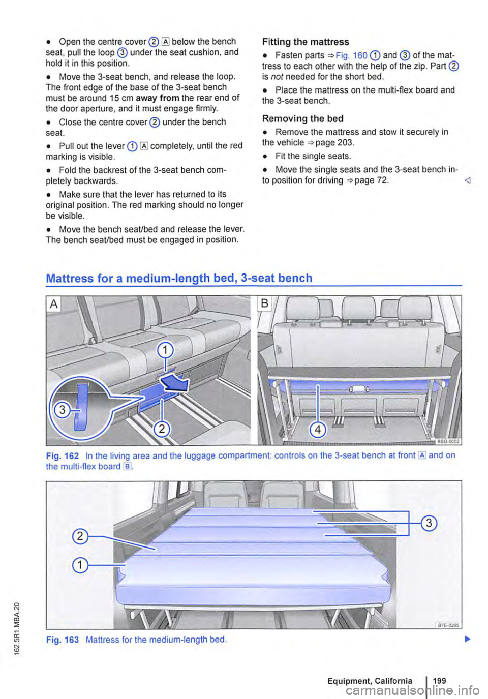
• Open the centre cover® below the bench seat, pull the loop @ under the seat cushion, and hold it in this position.
• Move the 3-seat bench, and release the loop. The front edge of the base of the 3-seat bench must be around 15 cm away from the rear end of the door aperture, and it must engage firmly.
• Close the centre cover® under the bench seat.
• Pull out the lever completely, until the red marlling is visible.
• Fold the backrest of the 3-seat bench com-pletely backwards.
• Make sure that the lever has returned to its original position. The red marking should no longer be visible.
• Move the bench seaVbed and release the lever. The bench seaVbed must be engaged in position.
Fitting the mattress
• Fasten parts =>Fig. 160 G) and @ of the mat-tress to each other with the help of the zip. Part® is not needed for the short bed.
• Place the mattress on the multi-flex board and the 3-seat bench.
Removing the bed
• Remove the mattress and stow it securely in the vehicle =>page 203.
• Fit the single seats.
• Move the single seats and the 3-seat bench in-to position for driving =>page 72.
Fig. 162 In the living area and the luggage compartment. controls on the 3-seat bench at front E and on the multi-flex board e .
Fig. 163 Mattress for the medium-length bed.
Equipment, California 199
Page 200 of 486
,...-m First read and observe the Introductory L--W.I Information and safety warnings & on page 193.
The medium-length bed is around 1.80 metres long. The bed can only be set up In vehicles with a 3-seat bench and with the single seats removed.
Setting up the medium-length bed
• Push the multi-flex board backwards to the stop.
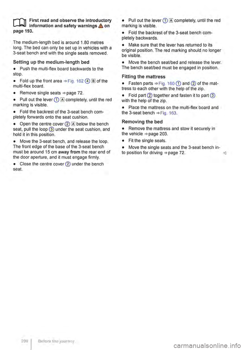
• Fold up the front area 162 @!ID of the multi-flex board.
• Remove single seats 72.
• Pull out the lever completely, until the red marking is visible.
• Fold the backrest of the 3-seat bench com-pletely forwards onto the seat cushion.
• Open the centre below the bench seat, pull the loop @ under the seat cushion, and hold it in this position.
• Move the 3-seat bench, and release the loop. The front edge of the base of the 3-seat bench must be around 15 cm away from the rear end of the door aperture, and it must engage firmly.
• Close the centre cover® under the bench seat.
200 Before tho JOurney
• Pull out the lever completely, until the red marking is visible.
• Fold the backrest of the 3-seat bench com-pletely backwards.
• Make sure that the lever has returned to its original position. The red marking should no longer be visible.
• Move the bench seaUbed and release the lever. The bench seaUbed must be engaged in position.
Fitting the mattress
• Fasten parts 160 CD and® of the mat-tress to each other with the help of the zip.
• Fold part® together and fasten it to part@ with the help of the zip.
• Place the mattress on the multi-flex board and the 3-seat bench 163.
Removing the bed
• Remove the mattress and stow it securely in the vehicle 203.
• Fit the single seats.
• Move the single seats and the 3-seat bench in-to position for driving 72.
Page 227 of 486
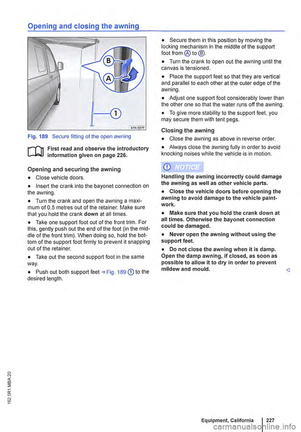
Fig. 189 Secure fitting of the open awning
r-1l1 First read and observe the introductory information given on page 226.
Opening and securing the awning
• Close vehicle doors.
• Insert the crank into the bayonet connection on the awning.
• Turn the crank and open the awning a maxi-mum of 0.5 metres out of the retainer. Make sure that you hold the crank down at all times.
• Take one support foot out of the front trim. For this, gently push out the end of the foot (in the mid-dle of the front trim). When doing so, hold the bot-tom of the support foot firmly to prevent it snapping out of the retainer.
• Take out the second support foot in the same way.
• Push out both support feet =>Fig. 189 G) to the desired length.
• Secure them in this position by moving the locking mechanism in the middle of the support foot from ®to@.
• Turn the crank to open out the awning until the canvas is tensioned.
• Place the support feet so that they are vertical and parallel to each other at the outer edge of the awning.
• Adjust one support foot considerably lower than the other one so that the water runs off the awning.
• To give more stability to the support feet, you may secure them with tent pegs.
Closing the awning
• Close the awning as above in reverse order.
• Always close the awning fully in order to avoid knocking noises while the vehicle is in motion.
CD
Handling the awning incorrectly could damage the awning as well as other vehicle parts.
• Close the vehicle doors before opening the awning to avoid damage to the vehicle paint-work.
• Make sure that you hold the crank down at all times. Otherwise the bayonet connection could be damaged.
• Never open the awning without using the support feet.
• Do not close the awning when it Is damp. Open the damp awning, if closed, as soon as possible to allow it to dry in order to prevent mildew and mould.
Page 229 of 486
Tables and camping chairs, California
CllJ Introduction
This chapter contains information on the following subjects:
Folding table in the sliding door . . . . . . . . . . . . 229
Folding the work table out and in . . . . . . . . . . 230
Moving the work table . . . . . . . . . . . . . . . . . • . 231
Camping chairs . . . . . . . . . . . . . . . . . . . . . . . . 232 Flyscreen element for the sliding window . . . . 232
Additional Information and warnings:
• Seat functions, front 69
• Seat functions, rear =>page 72
• Stowage 150
• Stowage areas, California 210
• Drink holder 153
• Tailgate 36
• Awning 226
Folding table in the sliding door
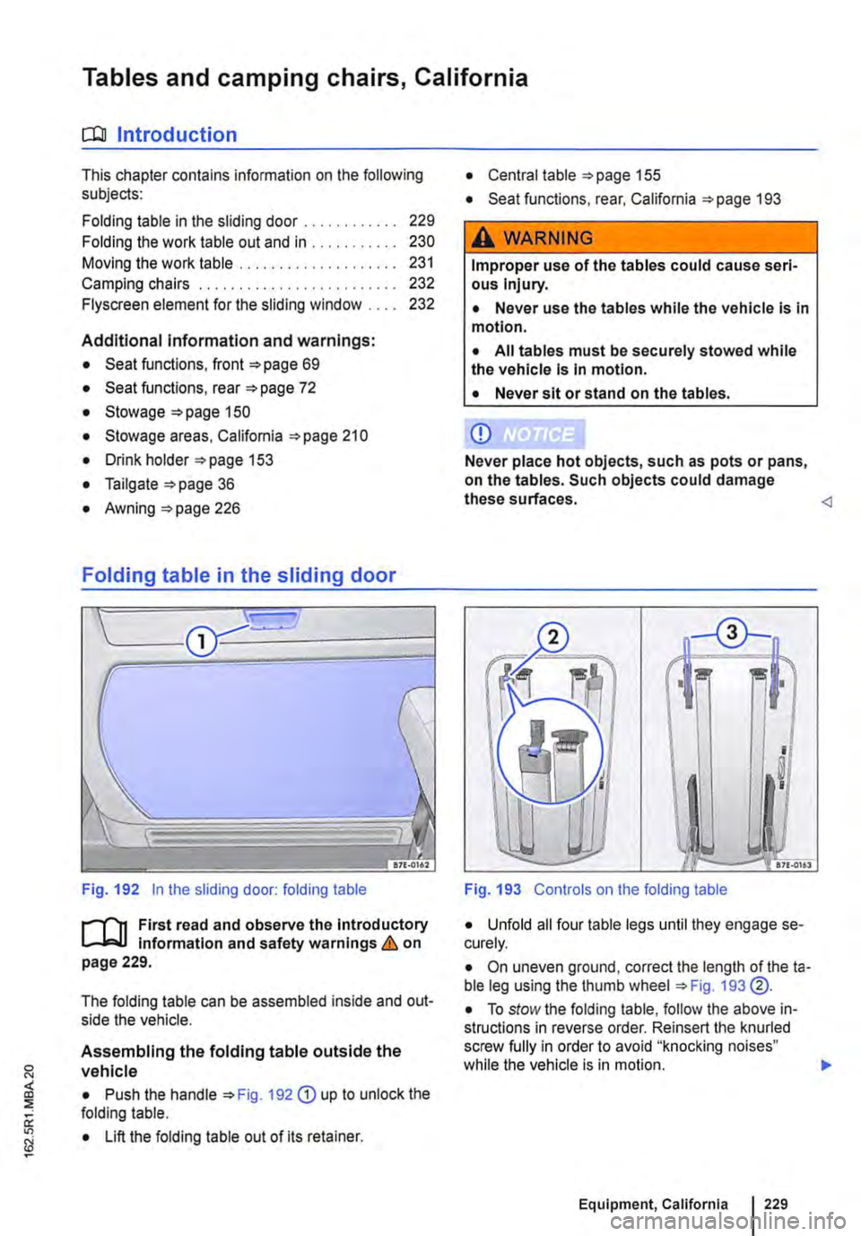
Fig. 192 in the sliding door: folding table
J"'"'"('n First read and observe the introductory L-Jo:.LI information and safety warnings & on page 229.
The folding table can be assembled inside and out-side the vehicle.
Assembling the folding table outside the vehicle
• Push the handle 192 G) up to unlock the folding table.
• Lift the folding table out of its retainer.
• Central table 155
• Seat functions, rear, California 193
,A WARNING
Improper use of the tables could cause seri-ous Injury.
• Never use the tables while the vehicle is in motion.
• All tables must be securely stowed while the vehicle is in motion.
• Never sit or stand on the tables.
CD
Never place hot objects, such as pots or pans, on the tables. Such objects could damage these surfaces.
I !! I
I
I
.. -17£.0161
Fig. 193 Controls on the folding table
• Unfold all four table legs until they engage se-curely.
• On uneven ground, correct the length of theta-ble leg using the thumb wheel 193 @.
• To stow the folding table, follow the above in-structions in reverse order. Reinsert the knurled screw fully in order to avoid "knocking noises" while the vehicle is in motion. .,.
Equipment, California 229
Page 295 of 486
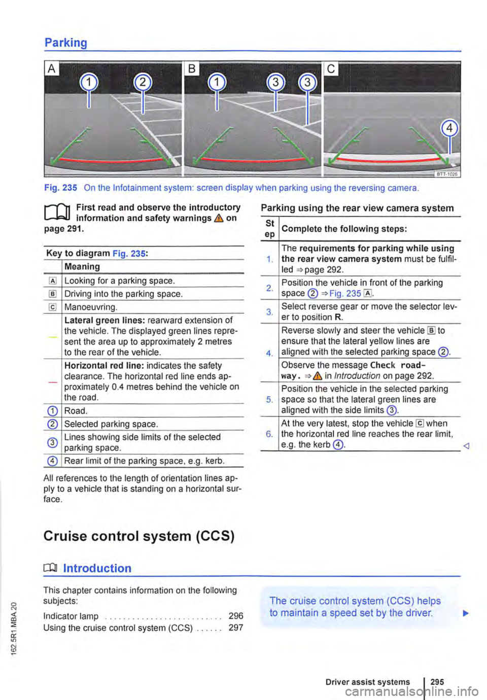
Fig. 235 On the lnfotainment system: screen display when parking using the reversing camera.
r-111 First read and observe the introductory L-L::.I.I information and safety warnings & on page 291.
Key to diagram Fig. 235:
Meaning
Looking for a parking space.
!ID Driving into the parking space.
[£! Manoeuvring.
Lateral green lines: rearward extension of the vehicle. The displayed green lines repre-sent the area up to approximately 2 metres to the rear of the vehicle.
Horizontal red line: indicates the safety clearance. The horizontal red line ends ap--proximately 0.4 metres behind the vehicle on the road.
CD Road.
® Selected parking space.
0 Lines showing side limits of the selected parking space.
@ Rear limit of the parking space, e.g. kerb.
All references to the length of orientation lines ap-ply to a vehicle that is standing on a horizontal sur-face.
Cruise control system (CCS)
[QJ Introduction
This chapter contains information on the following subjects:
Indicator lamp . . . . . . . . . . . . . . . . . . 296 Using the cruise control system (CCS) . . 297
Parking using the rear view camera system
St Complete the following steps: ep
The requirements for parking while using 1. the rear view camera system must be fulfil-led =>page 292.
2. Position the vehicle in front of the parking space ® =>Fig. 235
3. Select reverse gear or move the selector lev-er to position R.
Reverse slowly and steer the vehicle [ID to
4.
ensure that the lateral yellow lines are aligned with the selected parking space @.
Observe the message Check road-way. => & in Introduction on page 292.
Position the vehicle in the selected parking 5. space so that the lateral green lines are aligned with the side limits @.
At the very latest, stop the vehicle[£] when 6. the horizontal red line reaches the rear limit, e.g. the kerb@.
The cruise control system (CCS) helps
to maintain a speed set by the driver.
Driver assist systems 295
Page 339 of 486
Switching the childproof lock on and off
B7f·0201
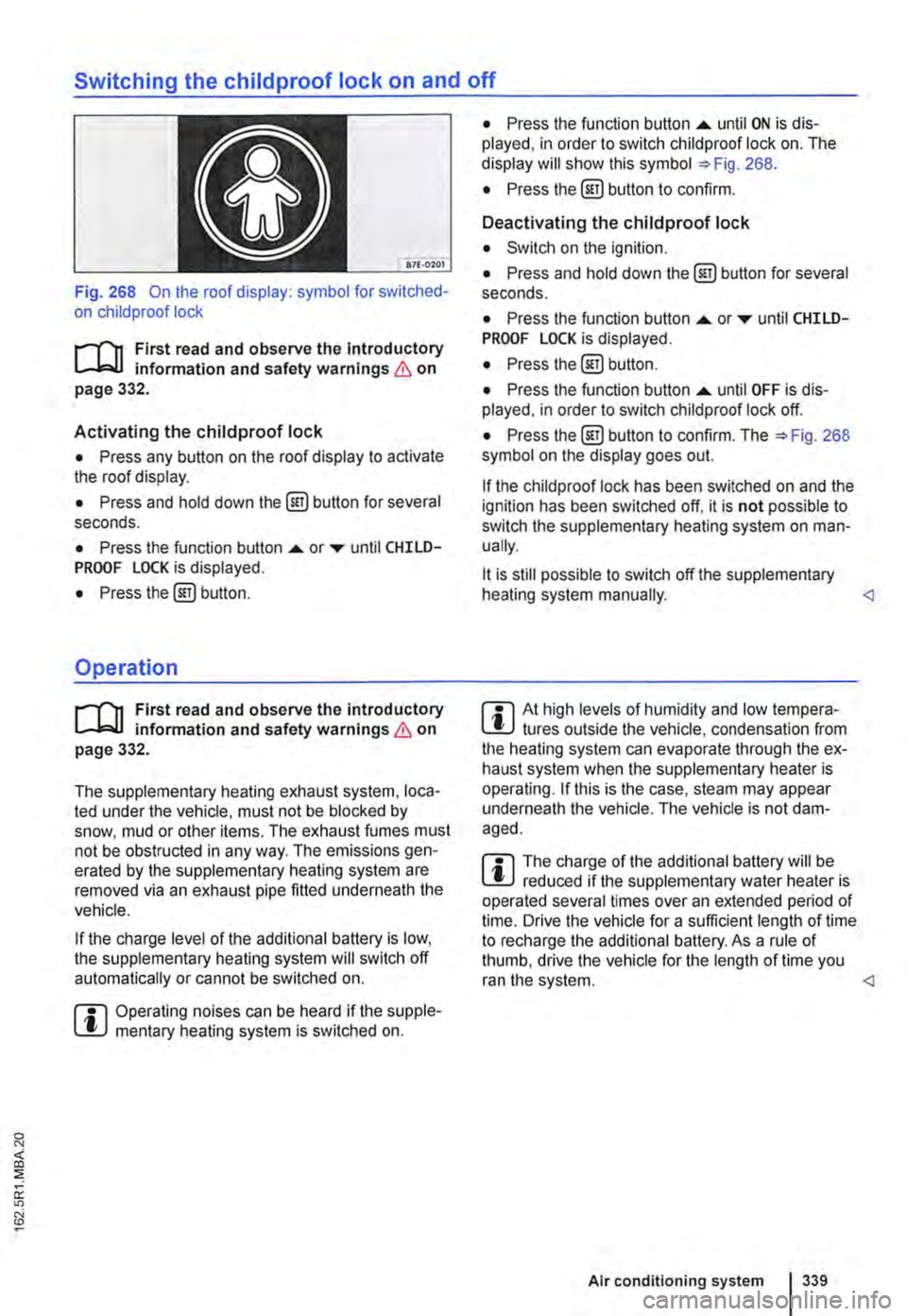
Fig. 268 On the roof display: symbol for switched-on child proof lock
r-T'n First read and observe the introductory L-.bU information and safety warnings & on page 332.
Activating the childproof lock
• Press any button on the roof display to activate the roof display.
• Press and hold down the @) button for several seconds.
• Press the function button .... or ..-until CHILD-PROOF LOCK is displayed.
• Press the@) button.
Operation
r-T'n First read and observe the introductory L-.bU information and safety warnings & on page 332.
The supplementary heating exhaust system, loca-ted under the vehicle, must not be blocked by snow, mud or other items. The exhaust fumes must not be obstructed in any way. The emissions gen-erated by the supplementary heating system are removed via an exhaust pipe fitted underneath the vehicle.
If the charge level of the additional battery is low, the supplementary heating system will switch off automatically or cannot be switched on.
m Operating noises can be heard if the supple-l!J mentary heating system is switched on.
• Press the function button .... until ON is dis-played, in order to switch child proof lock on. The display will show this symbol =>Fig. 268.
• Press the @] button to confirm.
Deactivating the childproof lock
• Switch on the ignition.
• Press and hold down the@] button for several seconds.
• Press the function button....._ or..-until CHILD-PROOF LOCK is displayed.
• Press the@) button.
• Press the function button .... until OFF is dis-played. in order to switch child proof lock off.
• Press the@) button to confirm. The =>Fig. 268 symbol on the display goes out.
If the child proof lock has been switched on and the ignition has been switched off, it is not possible to switch the supplementary heating system on man-ually.
lt is still possible to switch off the supplementary heating system manually.
r::l The charge of the additional battery will be W reduced if the supplementary water heater is operated several times over an extended period of time. Drive the vehicle for a sufficient length of time to recharge the additional battery. As a rule of thumb, drive the vehicle for the length of time you ran the system.
Page 369 of 486
Storing tyres
Mark tyres before you remove them to indicate the direction of rotation. This ensures you will be able to mount them correctly when you replace them (left, right, front, rear). When removed, the wheels or tyres should be stored in a cool, dry and pref-erably dark place. Do not store tyres mounted on the rim vertically.
Any tyres not fitted on rims should be kept in suita-ble sleeves to protect against dirt and should be stored vertically (standing on the tread).
All-terrain tyres
Some vehicles can be fitted at the factory with "all-terrain tyres". These tyres have a deep-tread pro-file that alters the vehicle's driving properties (such as comfort, consumption, braking distance, corner-Ing behaviour, rolling noise)=>&.
A WARNING
Corrosive liquids and other substances can cause visible and Invisible damage to the tyres, which can cause the tyre to burst.
• Always keep chemicals, oils, lubricants, fuel, brake fluid and other corrosive substan-ces away from the tyres.
A WARNING
Old tyres (even if never used) can suddenly lose pressure or burst, especially at high speeds. This can cause accidents and seri-ous injuries.
• Avoid using tyres that are more than six years old. If you have no alternative, drive slowly and with extra care at all times.
Rims
,....-('n First read and observe the Introductory L-J.:.ll information and safety warnings & on page 367.
The design of the wheel bolts is matched to the rims. If different rims are fitted, the correct wheel bolts with the right length and correctly shaped bolt heads must be used. This ensures that wheels are fitted securely and that the brake system works properly =>page 420.
For technical reasons, it is not generally possible to use the wheels from other vehicles. This can al-so apply to wheels of the same vehicle type.
A WARNING
The deep-tread profile of all-terrain tyres can considerably increase the braking distance or cornering behaviour and thus cause acci-dents and serious injuries.
• Always bear the modified vehicle handling in mind, and drive carefully.
CD
Avoid heavy impacts and drive round obstacles whenever possible. Tyres, particularly low-pro-file tyres, can be considerably compressed and deformed by potholes and curb edges especial-ly. This can cause the tyre's webbing reinforce-ment to brake, and cause dents or rips on the side walls or deformations or cracks on the rims.
Old tyres should be disposed of as required !!IS by legislation.
Wheel bolts
Wheel boils must always be tightened with the cor-rect tightening torque =>page 420.
Rims with bolted-on rings
Rims with bolted-on rings consist of several com-ponents. These components are fastened using special bolts and special fastening technology. This ensures that the wheel functions proper1y, does not leak, remains safe and runs true. For this reason, damaged rims should be replaced. They may only .,..
Wheels and tyres I 369