2019 TOYOTA LAND CRUISER weight
[x] Cancel search: weightPage 340 of 624

340
LC200_OM_OM60Q99U_(U)
4-5. Using the driving support systems
Observe the following precautions. Failure to do so may result in an
unexpected accident. Al so, when driving, make sure to directly con-
firm the safety of your surroundings and the area to the rear o f the
vehicle.
When using the Multi-terrain Monitor
WARNING
■ Conditions under which the Multi-terrain Monitor should not be used
Do not use the Multi-terrain Monitor in the following situations. The system
may not operate properly, resulting in an unexpected accident.
● When driving on an icy, snow-covered or otherwise slippery road surface
● When using tire chains or a spare tire
● When either front door or the back door is not completely close d
● When driving on an uneven road, such as a hill
● When tires or suspension parts other than those specified are e quipped
When the tires are replaced, the position indicated by the guid e lines dis-
played on the screen may differ.
■ Guide lines
The tire position indicator lines and vehicle position indicator lines may differ
from actual vehicle positions depending on the number of passen gers,
cargo weight, road grade, road surface conditions, brightness o f the sur-
rounding environment, etc. Always drive the vehicle while confi rming the
safety of your surroundings.
Page 345 of 624
LC200_OM_OM60Q99U_(U)
3454-5. Using the driving support systems
4
Driving
■Panoramic view display range
●In the panoramic view, the system processes and displays images acquired
form the 4 cameras under the assumption that the vehicle is on a flat road
surface. Therefore, the display may appear as follows.
• Three-dimensional objects may appear to have fallen over, and be long and thin or bigger than they actually are
• Three-dimensional objects at a point higher than the surface o f the road
may appear further away than they actually are, or may not appe ar
• Tall objects may appear to emerge from the image processing se ams
● Inconsistencies in the brightness of images from each camera may occur
depending on lighting conditions.
● The displayed image may not be aligned when the tilt or height of the vehi-
cle changed due to the number of passengers, cargo weight or re maining
quantity of gasoline.
● Images and guide lines may not be properly displayed when the d oors are
not completely closed.
● The relative distances between the vehicle icon and road surfac e or an
obstacle displayed in the panoramic view may differ from the ac tual state.
● If an illuminated license plate is used, it may appear on the s creen.
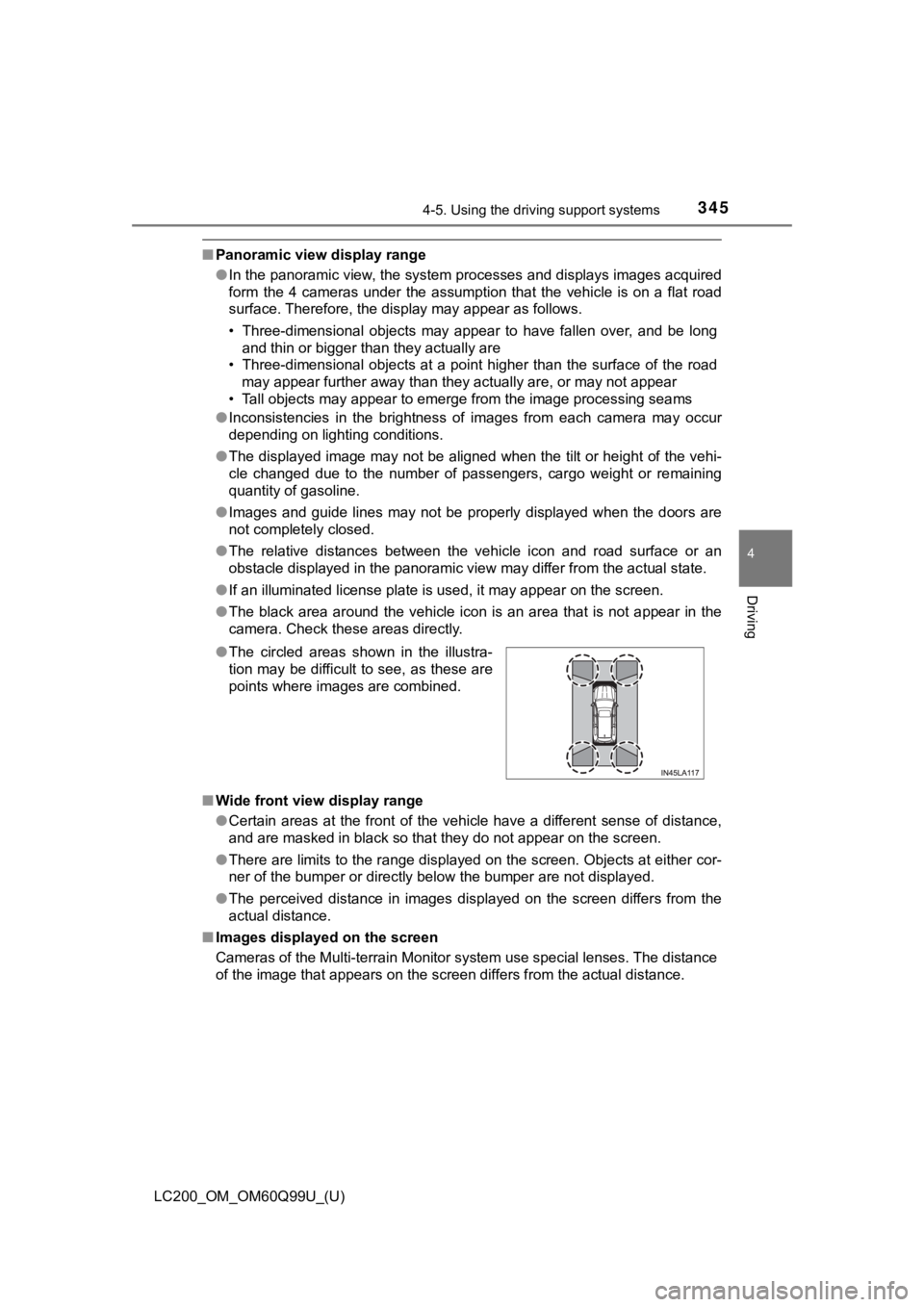
● The black area around the vehicle icon is an area that is not a ppear in the
camera. Check these areas directly.
■ Wide front view display range
●Certain areas at the front of the vehicle have a different sense of distance,
and are masked in black so that they do not appear on the scree n.
● There are limits to the range displayed on the screen. Objects at either cor-
ner of the bumper or directly below the bumper are not displaye d.
● The perceived distance in images displayed on the screen differ s from the
actual distance.
■ Images displayed on the screen
Cameras of the Multi-terrain Monitor system use special lenses. The distance
of the image that appears on the screen differs from the actual distance.
●
The circled areas shown in the illustra-
tion may be difficult to see, as these are
points where images are combined.
Page 349 of 624
LC200_OM_OM60Q99U_(U)
3494-5. Using the driving support systems
4
Driving
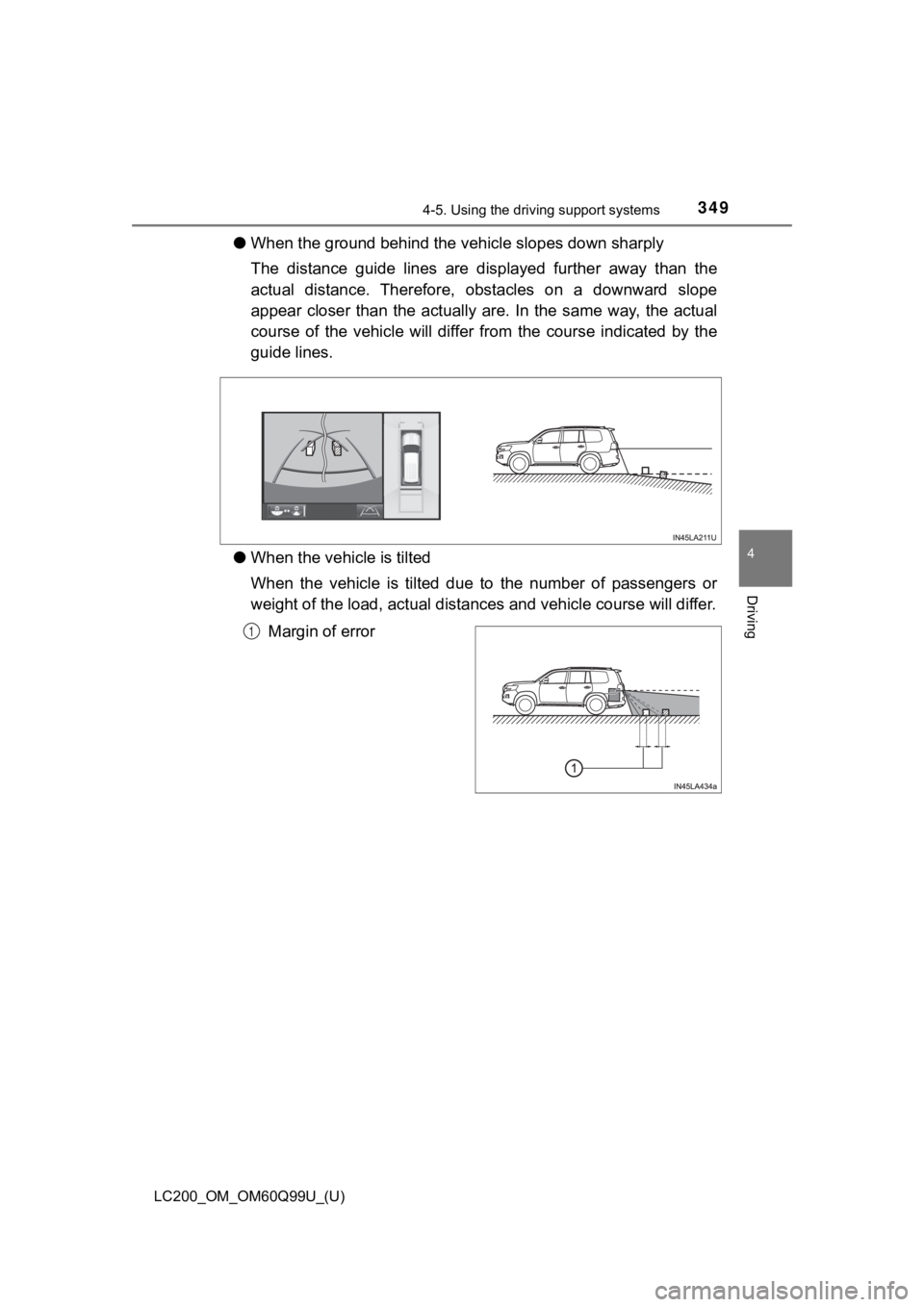
●When the ground behind the ve hicle slopes down sharply
The distance guide lines are displayed further away than the
actual distance. Ther efore, obstacles on a downward slope
appear closer than the actually are. In the same way, the actua l
course of the vehicle will differ from the course indicated by the
guide lines.
● When the vehicle is tilted
When the vehicle is tilted due to the number of passengers or
weight of the load, ac tual distances and vehicle course will di ffer.
Margin of error
1
Page 353 of 624
LC200_OM_OM60Q99U_(U)
3534-5. Using the driving support systems
4
Driving
■Differences between the panoramic view, rear view and wide
rear view and actual roads
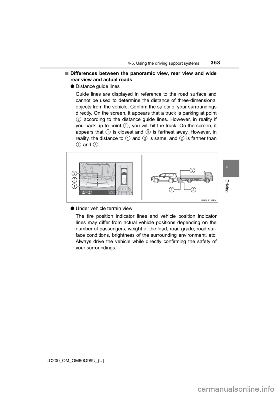
●Distance guide lines
Guide lines are displayed in reference to the road surface and
cannot be used to determine th e distance of three-dimensional
objects from the vehicle. Confirm the safety of your surroundin gs
directly. On the screen, it appears that a truck is parking at point
according to the distance guide lines. However, in reality if
you back up to point , you will hit the truck. On the screen, i t
appears that is closest and is farthest away. However, in
reality, the distance to and is same, and is farther than and .
● Under vehicle terrain view
The tire position indicator lines and vehicle position indicato r
lines may differ from actual v ehicle positions depending on the
number of passengers, weight of the load, road grade, road sur-
face conditions, brightness of the surrounding environment, etc .
Always drive the vehicle while directly confirming the safety o f
your surroundings.
2
1
13
132
13
Page 476 of 624
476
LC200_OM_OM60Q99U_(U)
6-3. Do-it-yourself maintenance
■When to replace your vehicle’s tires
Tires should be replaced if:
●The treadwear indicators are showing on a tire.
●You have tire damage such as cuts, splits, cracks deep enough t o
expose the fabric, and bulges indicating internal damage
●A tire goes flat repeatedly or c annot be properly repaired due to the size
or location of a cut or other damage
If you are not sure, consult with your Toyota dealer.
■Replacing tires and wheels
If the ID code of the tire press ure warning valve and transmitt er is not reg-
istered, the tire pressure warni ng system will not work properly. A f t e r d r i v -
ing for about 20 minutes, the tire pressure warning light blink s for 1
minute and stays on to indi cate a system malfunction.
■Tire life
Any tire over 6 years old must be checked by a qualified techni cian even
if it has seldom or never been u sed or damage is not obvious.
■Routine tire inflation pressure checks
The tire pressure warning system does not replace routine tire inflation
pressure checks. Make sure to chec k tire inflation pressure as part of
your routine of daily vehicle checks.
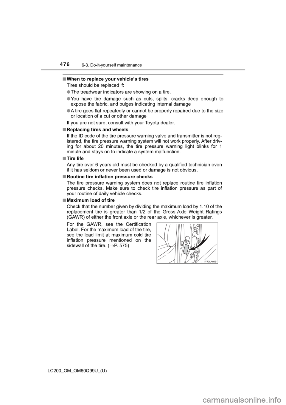
■Maximum load of tire
Check that the number given by dividing the maximum load by 1.1 0 of the
replacement tire is greater than 1/2 of the Gross Axle Weight R atings
(GAWR) of either the front axle or the rear axle, whichever is greater.
For the GAWR, see the Certification
Label. For the maximum load of the tire,
see the load limit at maximum cold tire
inflation pressure mentioned on the
sidewall of the tire. ( P. 5 7 5 )
Page 484 of 624

484
LC200_OM_OM60Q99U_(U)
6-3. Do-it-yourself maintenance
■Instructions for checking tire inflation pressure
When checking tire inflation pressure, observe the following:
●Check only when the tires are cold.
If your vehicle has been parked for at least 3 hours and has no t been
driven for more than 1 mile or 1.5 km, you will get an accurate cold tire
inflation pressure reading.
●Always use a tire pressure gauge.
It is difficult to judge if a tire is properly inflated based o nly on its appear-
ance.
●It is normal for the tire inflation pressure to be higher after driving as
heat is generated in the tire. Do not reduce tire inflation pre ssure after
driving.
●Never exceed the vehicle capacity weight.
Passengers and luggage weight should be placed so that the vehi cle is
balanced.
WARNING
■Proper inflation is critical to save tire performance
Keep your tires properly inflated.
If the tires are not properly in flated, the following conditions may occur
which could lead to an accident r esulting in death or serious injury:
●Excessive wear
●Uneven wear
●Poor handling
●Possibility of blowouts resulting from overh eated tires
●Air leaking from between tire and wheel
●Wheel deformation and/ or tire damage
●Greater possibility of tire damage while driving (due to road hazards,
expansion joints, sharp ed ges in the road, etc.)
NOTICE
■When inspecting and adjusti ng tire inflation pressure
Be sure to put the tire valve caps back on.
If a valve cap is not installed , dirt or moisture may get into the valve and
cause an air leak, resulting in decreased tire inflation pressu re.
Page 564 of 624
564
LC200_OM_OM60Q99U_(U)
8-1. Specifications
Maintenance data (fuel, oil level, etc.)
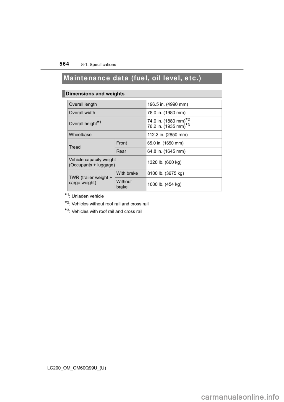
*1: Unladen vehicle
*2: Vehicles without roof rail and cross rail
*3: Vehicles with roof rail and cross rail
Dimensions and weights
Overall length196.5 in. (4990 mm)
Overall width78.0 in. (1980 mm)
Overall height*174.0 in. (1880 mm)*2
76.2 in. (1935 mm)*3
Wheelbase112.2 in. (2850 mm)
TreadFront65.0 in. (1650 mm)
Rear64.8 in. (1645 mm)
Vehicle capacity weight
(Occupants + luggage)1320 lb. (600 kg)
TWR (trailer weight +
cargo weight)With brake8100 lb. (3675 kg)
Without
brake1000 lb. (454 kg)
Page 581 of 624
LC200_OM_OM60Q99U_(U)
5818-1. Specifications
8
Vehicle specifications
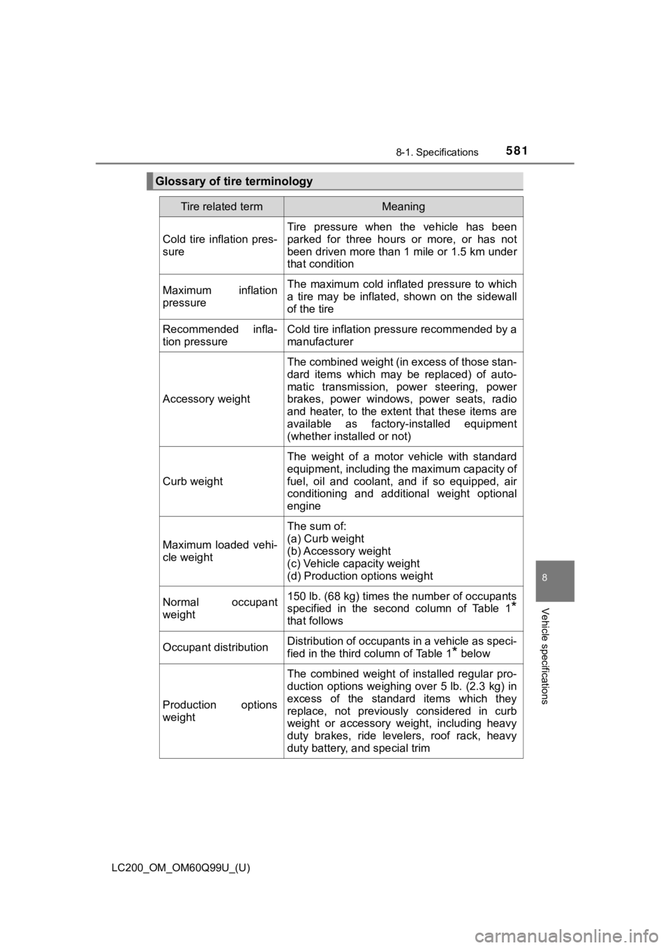
Glossary of tire terminology
Tire related termMeaning
Cold tire inflation pres-
sure
Tire pressure when the vehicle has been
parked for three hours or more, or has not
been driven more than 1 mile or 1.5 km under
that condition
Maximum inflation
pressureThe maximum cold inflated pressure to which
a tire may be inflated, shown on the sidewall
of the tire
Recommended infla-
tion pressureCold tire inflation pressure recommended by a
manufacturer
Accessory weight
The combined weight (in excess of those stan-
dard items which may be replaced) of auto-
matic transmission, power steering, power
brakes, power windows, power seats, radio
and heater, to the extent that these items are
available as factory-installed equipment
(whether installed or not)
Curb weight
The weight of a motor vehicle with standard
equipment, including the maximum capacity of
fuel, oil and coolant, and if so equipped, air
conditioning and additional weight optional
engine
Maximum loaded vehi-
cle weight
The sum of:
(a) Curb weight
(b) Accessory weight
(c) Vehicle capacity weight
(d) Production options weight
Normal occupant
weight150 lb. (68 kg) times the number of occupants
specified in the second column of Table 1
*
that follows
Occupant distributionDistribution of occupants in a vehicle as speci-
fied in the third column of Table 1
* below
Production options
weight
The combined weight of installed regular pro-
duction options weighing over 5 lb. (2.3 kg) in
excess of the standard items which they
replace, not previously considered in curb
weight or accessory weight, including heavy
duty brakes, ride levelers, roof rack, heavy
duty battery, and special trim