2019 TOYOTA LAND CRUISER ECO mode
[x] Cancel search: ECO modePage 23 of 624
23Pictorial index
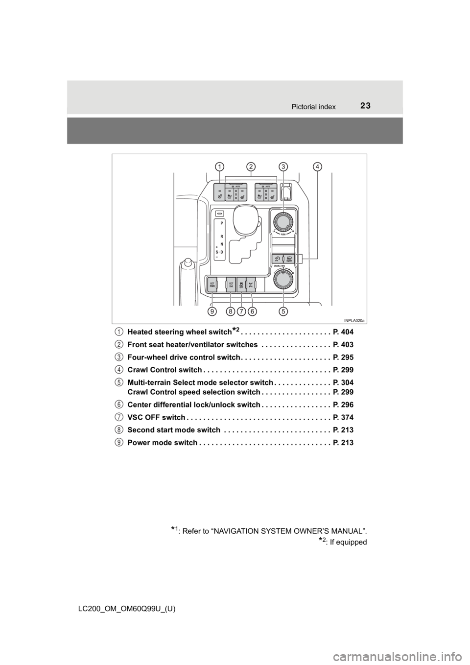
LC200_OM_OM60Q99U_(U)Heated steering wheel switch
*2. . . . . . . . . . . . . . . . . . . . . . P. 404
Front seat heater/ventilator switches . . . . . . . . . . . . . . . . . P. 403
Four-wheel drive control switch . . . . . . . . . . . . . . . . . . . . . . P. 295
Crawl Control switch . . . . . . . . . . . . . . . . . . . . . . . . . . . . . . . P. 299
Multi-terrain Select mode selector switch . . . . . . . . . . . . . . P. 304
Crawl Control speed selection switch . . . . . . . . . . . . . . . . . P. 299
Center differential lock/unlock switch . . . . . . . . . . . . . . . . . P. 296
VSC OFF switch . . . . . . . . . . . . . . . . . . . . . . . . . . . . . . . . . . . P. 374
Second start mode switch . . . . . . . . . . . . . . . . . . . . . . . . . . P. 213
Power mode switch . . . . . . . . . . . . . . . . . . . . . . . . . . . . . . . . P. 213
*1: Refer to “NAVIGATION S YSTEM OWNER’S MANUAL”.
*2: If equipped
1
2
3
4
5
6
7
8
9
Page 29 of 624
291-1. For safe use
LC200_OM_OM60Q99U_(U)
1
For safety and security
WARNING
Observe the following precautions.
Failure to do so may cause the driver’s floor mat to slip, possibly interfering
with the pedals while driving. An unexpectedly high speed may result or it may
become difficult to stop the vehicle. This could lead to an acc ident, resulting in
death or serious injury.
■ When installing the driver’s floor mat
● Do not use floor mats designed for other models or different mo del year
vehicles, even if they are Toyota Genuine floor mats.
● Only use floor mats designed for the driver’s seat.
● Always install the floor mat securely using the retaining hooks (clips) pro-
vided.
● Do not use two or more floor mats on top of each other.
● Do not place the floor mat bottom-side up or upside-down.
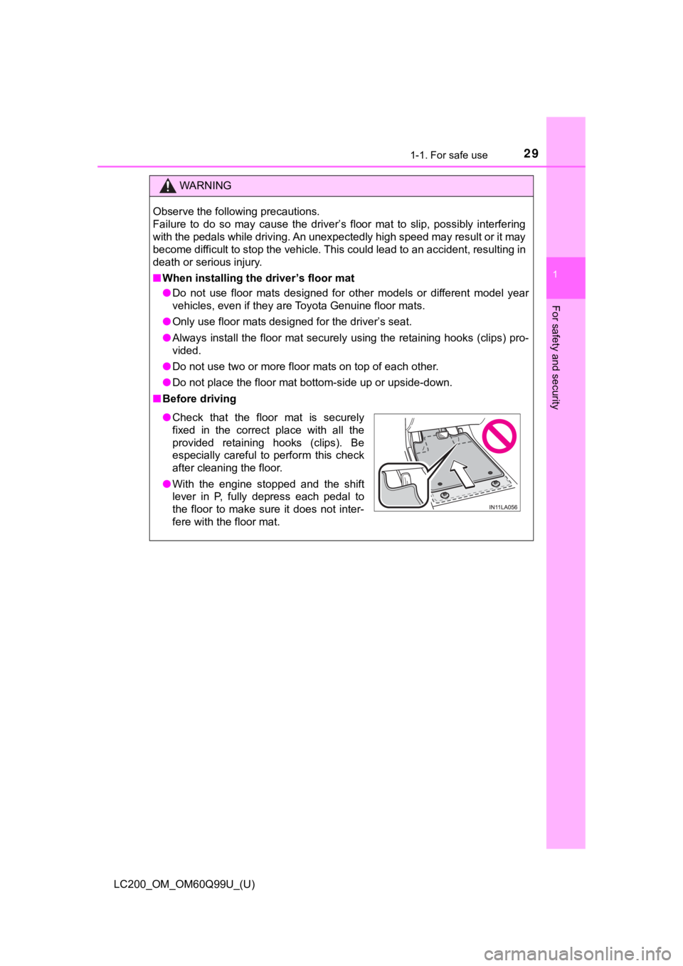
■ Before driving
● Check that the floor mat is securely
fixed in the correct place with all the
provided retaining hooks (clips). Be
especially careful to perform this check
after cleaning the floor.
● With the engine stopped and the shift
lever in P, fully depress each pedal to
the floor to make sure it does not inter-
fere with the floor mat.
Page 68 of 624
681-1. For safe use
LC200_OM_OM60Q99U_(U)
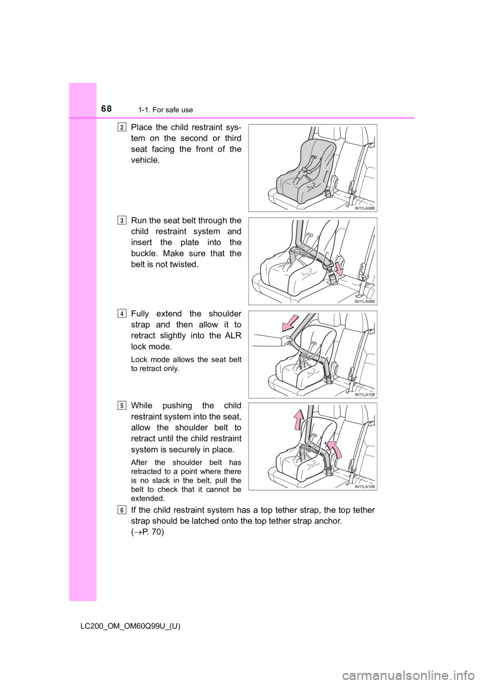
Place the child restraint sys-
tem on the second or third
seat facing the front of the
vehicle.
Run the seat belt through the
child restraint system and
insert the plate into the
buckle. Make sure that the
belt is not twisted.
Fully extend the shoulder
strap and then allow it to
retract slightly into the ALR
lock mode.
Lock mode allows the seat belt
to retract only.
While pushing the child
restraint system into the seat,
allow the shoulder belt to
retract until the child restraint
system is securely in place.
After the shoulder belt has
retracted to a point where there
is no slack in the belt, pull the
belt to check that it cannot be
extended.
If the child restraint system has a top tether strap, the top tether
strap should be latched onto t he top tether strap anchor.
( P. 70)
2
3
4
5
6
Page 72 of 624
721-1. For safe use
LC200_OM_OM60Q99U_(U)
WARNING
■When installing a booster seat
To prevent the belt from going into ALR lock mode, do not fully extend the
shoulder belt. ALR mode causes the belt to tighten only. This c ould cause
injury or discomfort to the child. ( P. 36)
■ When installing a child restraint system
Follow the directions given in the child restraint system insta llation manual
and fix the child restraint system securely in place.
If the child restraint system is not correctly fixed in place, the child or other
passengers may be seriously injured or even killed in the event of sudden
braking, sudden swerving or an accident.
● When installing a child restraint system on the second center s eat, adjust
both seat cushions to the same position and align both seatback s at the
same angle. Otherwise, the child restraint system cannot be sec urely
restrained and this may cause death or serious injuries in the event of sud-
den braking, sudden swerving or an accident.
● When using the LATCH anchors for a child restraint system, move the seat
as far back as possible, with the seatback close to the child restraint sys-
tem.
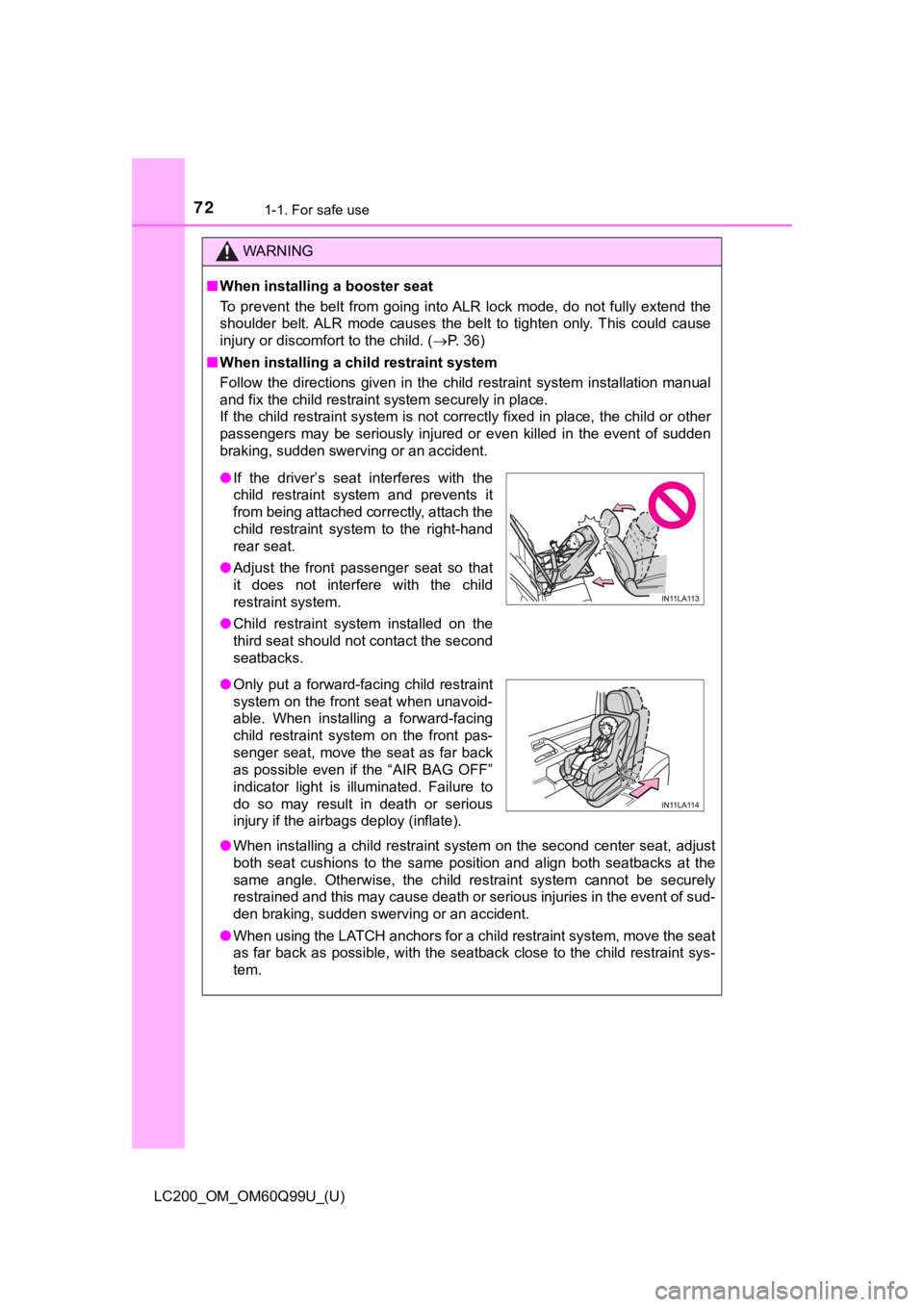
● If the driver’s seat interferes with the
child restraint system and prevents it
from being attached correctly, attach the
child restraint system to the right-hand
rear seat.
● Adjust the front passenger seat so that
it does not interfere with the child
restraint system.
● Child restraint system installed on the
third seat should not contact the second
seatbacks.
● Only put a forward-facing child restraint
system on the front seat when unavoid-
able. When installing a forward-facing
child restraint system on the front pas-
senger seat, move the seat as far back
as possible even if the “AIR BAG OFF”
indicator light is illuminated. Failure to
do so may result in death or serious
injury if the airbags deploy (inflate).
Page 77 of 624
771-2. Emergency assistance
LC200_OM_OM60Q99U_(U)
1
For safety and security
●Automatic Collision Notification, Emergency Assistance and Stolen Vehicle
Location are available in the United States, including Hawaii a nd Alaska,
Puerto Rico and Canada, and Enhanced Roadside Assistance are av ailable
in the United States, Puerto Rico and Canada.
● Automatic Collision Notification, Emergency Assistance, Stolen Vehicle and
Enhanced Road Assistance are not available in the U.S. Virgin I slands.
For vehicles first sold in the U.S. Virgin Islands, no Safety Connect services will
function in or outside the U.S. Virgin Islands.
● Safety Connect services are not subject to section 255 of the T elecommuni-
cations Act and the device is not TTY compatible.
■ Languages
The Safety Connect response center will offer support in multip le languages.
The Safety Connect system will offer voice prompts in English, Spanish, and
French. Please indicate your language of choice when enrolling.
■ When contacting the response center
You may be unable to contact the response center if the network is busy.
■ Safety Connect backup battery depletion
An exclusive backup battery is built in to assist the Automatic Collision Notifi-
cation, which is activated when impact above a certain level is applied to the
vehicle, or when the airbags operate. This battery is a primary battery, and
cannot be recharged. The red LED indicator will flash to indica te that the bat-
tery should be replaced.
The backup battery will need to be replaced if the Automatic Co llision Notifi-
cation operates for 60 seconds or more. For replacement, consul t your Toy-
ota dealer.
When the engine switch is turned to IGNITION ON mode, the red i ndi-
cator light comes on for 2 seconds then turns off. Afterward, t he green
indicator light comes on, indicat ing that the service is active.
The following indicator light patterns indicate specific system usage
conditions:
● Green indicator light on = Active service
● Green indicator light flashing = Safety Connect call in process
● Red indicator light (except at vehicle start-up) = System malfunction
(contact your Toyota dealer)
● No indicator light (off) = Saf ety Connect service not active
Safety Connect LED light Indicators
Page 83 of 624
831-3. Theft deterrent system
LC200_OM_OM60Q99U_(U)
1
For safety and security
Alar m
The alarm uses light and sound to give an alert when an intrusion is
detected.
The alarm is triggered in the following situations when the ala rm is
set:
● A locked door is unlocked or opened in any way other than using
the entry function or wireless remote control. (The doors will lock
again automatically.)
● The hood is opened.
● The battery is reconnected.
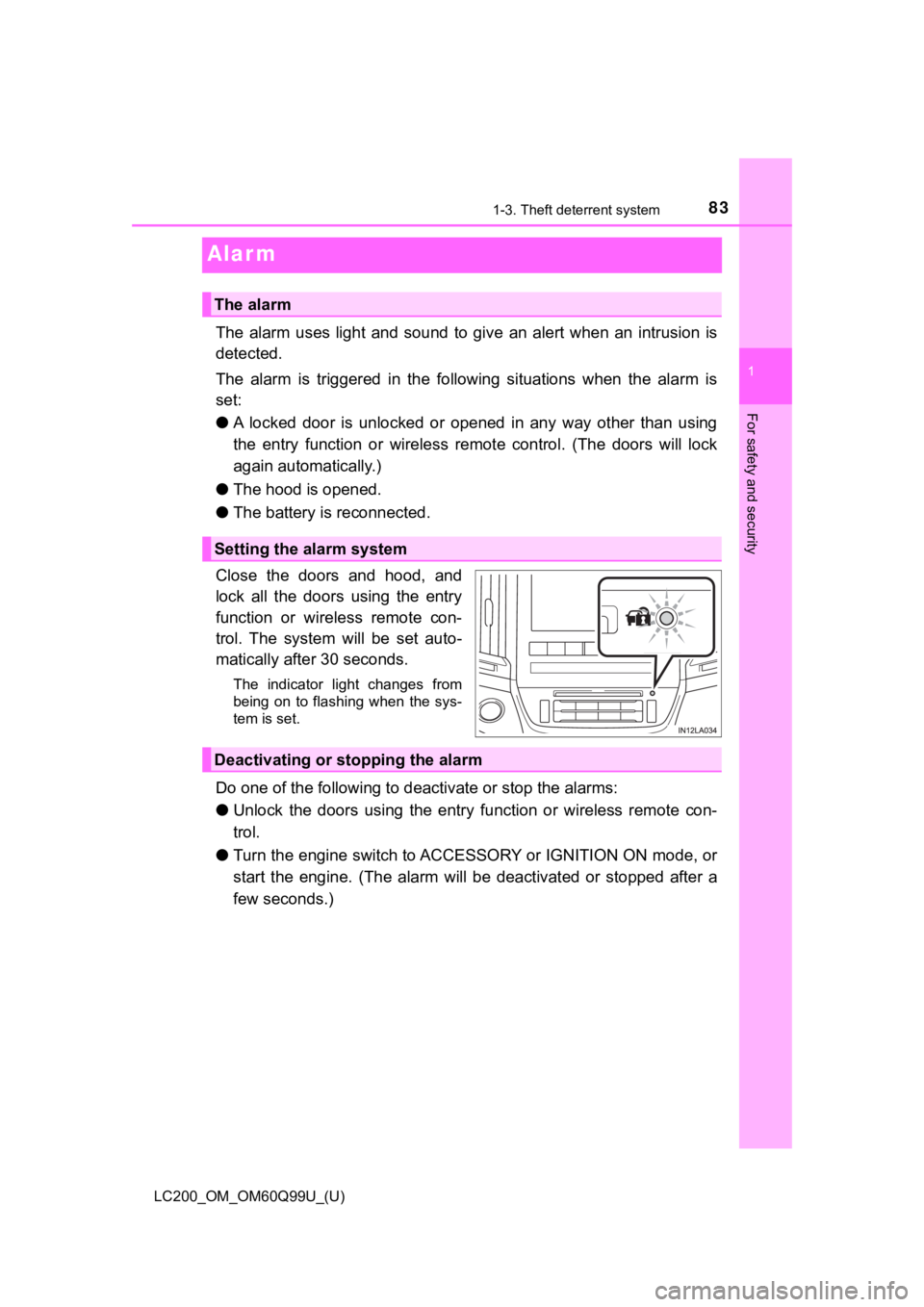
Close the doors and hood, and
lock all the doors using the entry
function or wireless remote con-
trol. The system will be set auto-
matically after 30 seconds.
The indicator light changes from
being on to flashing when the sys-
tem is set.
Do one of the following to d eactivate or stop the alarms:
● Unlock the doors using the entry function or wireless remote co n-
trol.
● Turn the engine switch to ACCESSORY or IGNITION ON mode, or
start the engine. (The alarm w ill be deactivated or stopped after a
few seconds.)
The alarm
Setting the alarm system
Deactivating or stopping the alarm
Page 89 of 624
LC200_OM_OM60Q99U_(U)
892. Instrument cluster
2
Instrument cluster
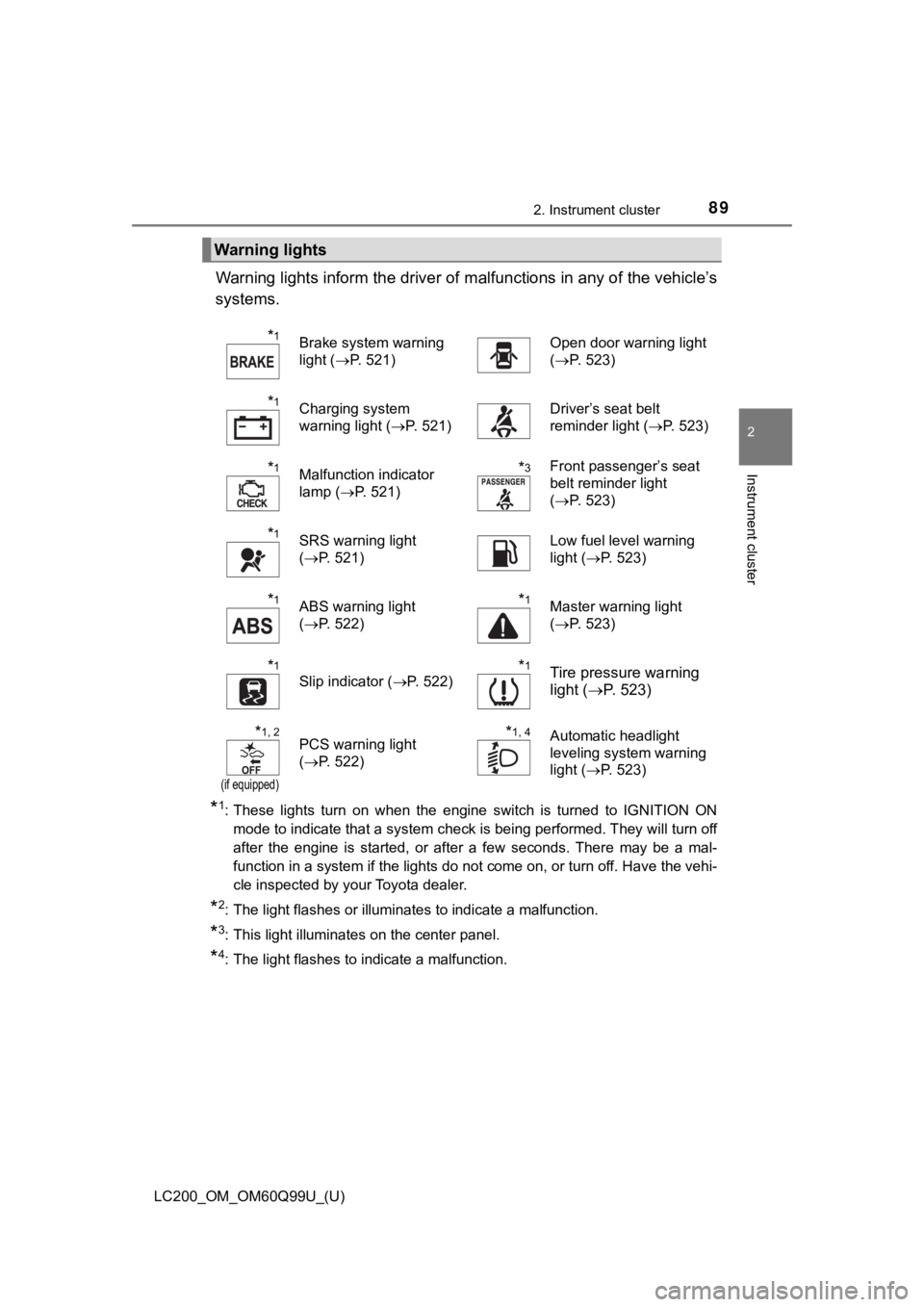
Warning lights inform the driver of malfunctions in any of the vehicle’s
systems.
*1: These lights turn on when the engine switch is turned to IGNIT ION ON
mode to indicate that a system check is being performed. They w ill turn off
after the engine is started, or after a few seconds. There may be a mal-
function in a system if the lights do not come on, or turn off. Have the vehi-
cle inspected by your Toyota dealer.
*2: The light flashes or illuminates to indicate a malfunction.
*3: This light illuminates on the center panel.
*4: The light flashes to indicate a malfunction.
Warning lights
*1Brake system warning
light ( P. 521)Open door warning light
(P. 523)
*1Charging system
warning light ( P. 521)Driver’s seat belt
reminder light ( P. 523)
*1Malfunction indicator
lamp (P. 521)*3Front passenger’s seat
belt reminder light
(P. 523)
*1SRS warning light
(P. 521)Low fuel level warning
light ( P. 523)
*1ABS warning light
(P. 522)*1Master warning light
(P. 523)
*1
Slip indicator ( P. 522)*1Tire pressure warning
light (P. 523)
*1, 2
(if equipped)
PCS warning light
(P. 522)*1, 4Automatic headlight
leveling system warning
light ( P. 523)
Page 90 of 624
90
LC200_OM_OM60Q99U_(U)
2. Instrument cluster
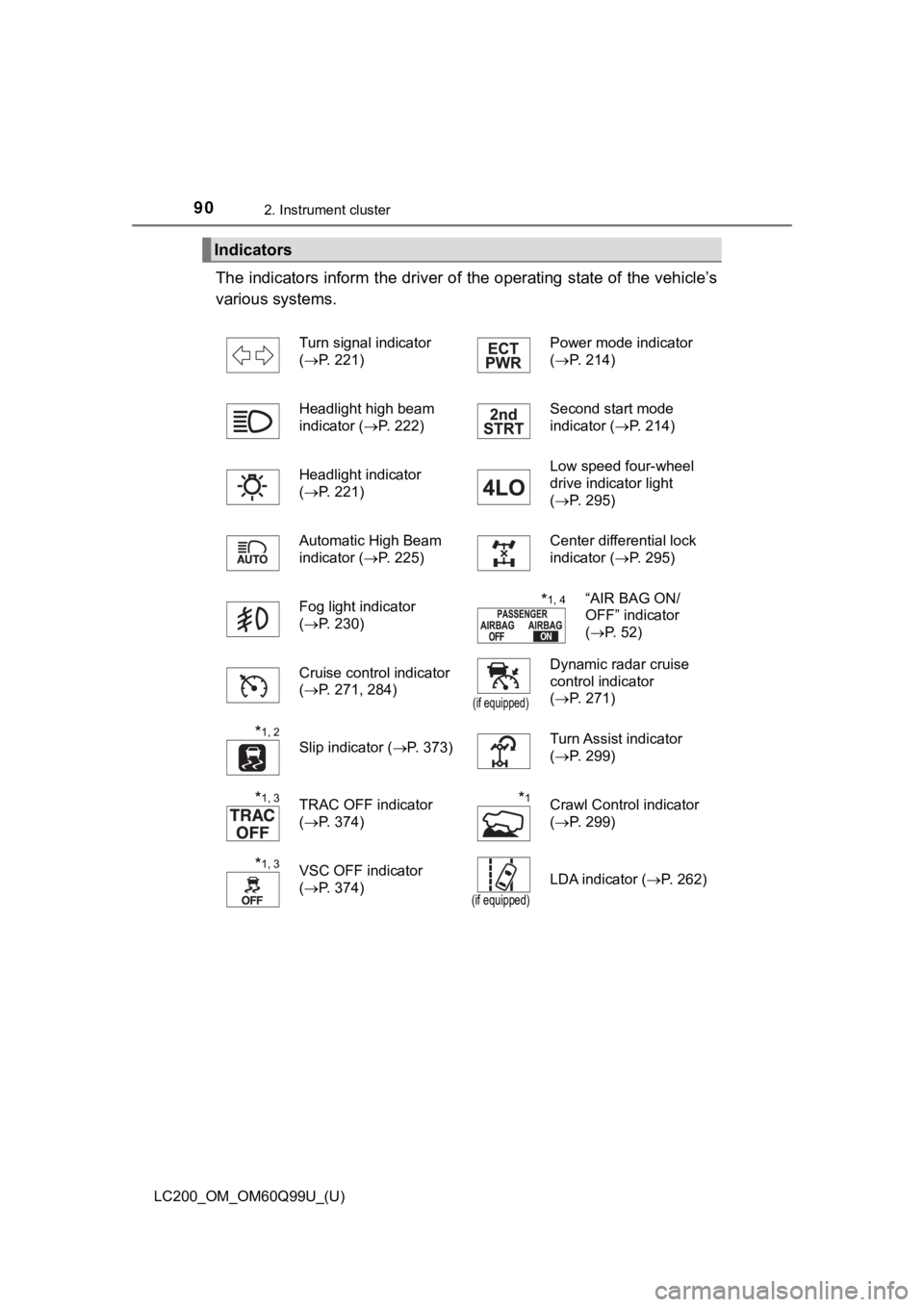
The indicators inform the driver of the operating state of the vehicle’s
various systems.
Indicators
Turn signal indicator
( P. 221) Power mode indicator
(
P. 214)
Headlight high beam
indicator ( P. 222) Second start mode
indicator (
P. 214)
Headlight indicator
( P. 221) Low speed four-wheel
drive indicator light
(
P. 295)
Automatic High Beam
indicator ( P. 225) Center differential lock
indicator (
P. 295)
Fog light indicator
( P. 230)
*1, 4“AIR BAG ON/
OFF” indicator
(P. 52)
Cruise control indicator
( P. 271, 284)
(if equipped)
Dynamic radar cruise
control indicator
(P. 271)
*1, 2
Slip indicator ( P. 373)Turn Assist indicator
(P. 299)
*1, 3TRAC OFF indicator
(P. 374)*1Crawl Control indicator
(P. 299)
*1, 3VSC OFF indicator
(P. 374)
(if equipped)
LDA indicator ( P. 262)