2019 Ram 2500 clock
[x] Cancel search: clockPage 61 of 696

GETTING TO KNOW YOUR VEHICLE 59
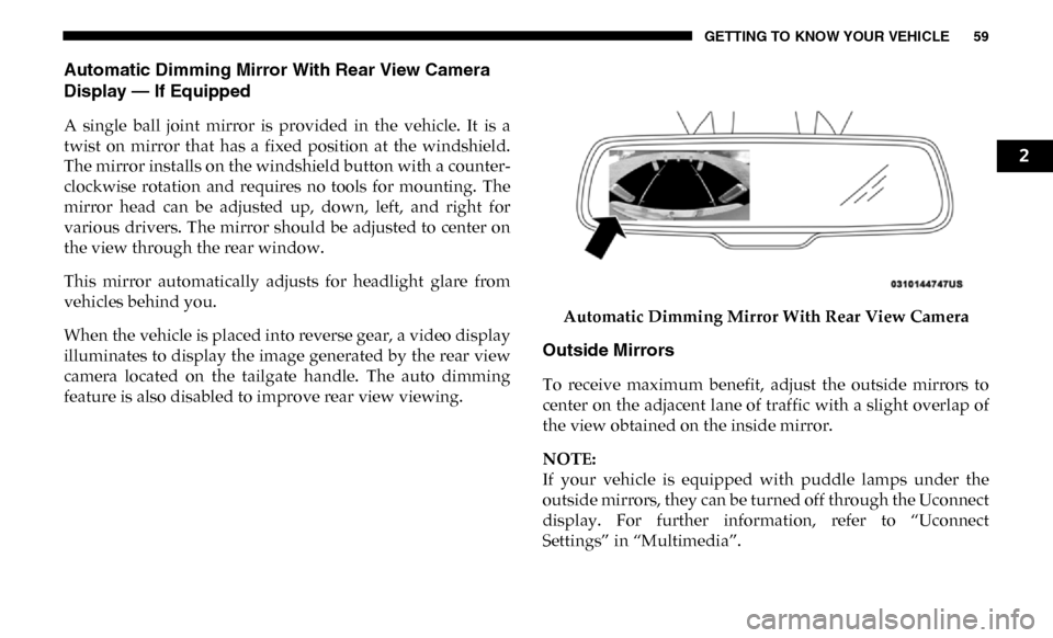
Automatic Dimming Mirror With Rear View Camera
Display — If Equipped
A single ball joint mirror is provided in the vehicle. It is a
twist on mirror that has a fixed position at the windshield.
The mirror installs on the windshield button with a counter-
clockwise rotation and requires no tools for mounting. The
mirror head can be adjusted up, down, left, and right for
various drivers. The mirror should be adjusted to center on
the view through the rear window.
This mirror automatically adjusts for headlight glare from
vehicles behind you.
When the vehicle is placed into reverse gear, a video display
illuminates to display the image generated by the rear view
camera located on the tailgate handle. The auto dimming
feature is also disabled to improve rear view viewing. Automatic Dimming Mirror With Rear View Camera
Outside Mirrors
To receive maximum benefit, adjust the outside mirrors to
center on the adjacent lane of traffic with a slight overlap of
the view obtained on the inside mirror.
NOTE:
If your vehicle is equipped with puddle lamps under the
outside mirrors, they can be turned off through the Uconnect
display. For further information, refer to “Uconnect
Settings” in “Multimedia”.
2
Page 69 of 696

GETTING TO KNOW YOUR VEHICLE 67
EXTERIOR LIGHTS
Multifunction Lever
The multifunction lever is located on the left side of the
steering column.Multifunction Lever
Headlight Switch
The headlight switch is located on the left side of the instru-
ment panel. This switch controls the operation of the head -
lights, parking lights, automatic headlights — if equipped,
instrument panel light dimming, cargo light — if equipped,
and fog lights — if equipped.
Headlight Switch
Rotate the headlight switch clockwise to the first detent for
parking light and instrument panel light operation. Rotate
the headlight switch to the second detent for headlight,
parking light, and instrument panel light operation.
2
Page 71 of 696

GETTING TO KNOW YOUR VEHICLE 69
If the windshield or Automatic High Beam Headlamp
Control mirror is replaced, the mirror must be re-aimed to
ensure proper performance. See a local authorized dealer.
To Activate
1. The Automatic High Beams are enabled through theUconnect system. Refer to “Uconnect Settings” in “Multi -
media” for further information.
2. Turn the headlight switch to the AUTO headlight posi -
tion.
3. Push the multifunction lever away from you (toward front of vehicle) to engage the high beam mode.
NOTE:
The Automatic High Beams will not activate until the vehicle
is at or above 12 mph (20 km/h).
To Deactivate
1. Pull the multifunction lever toward you (or rearward in vehicle) to manually deactivate the system (normal oper -
ation of low beams).
2. Push back on the multifunction lever to reactivate the system. The Automatic High Beams can also be deactivated through
the Uconnect system. Refer to “Uconnect Settings” in “Multi
-
media” for further information.
Flash-To-Pass
You can signal another vehicle with your headlights by
lightly pulling the multifunction lever toward you. This will
cause the high beam headlights to turn on, and remain on,
until the lever is released.
Automatic Headlights — If Equipped
This system automatically turns your headlights on or off
based on ambient light levels. To turn the system on, turn the
headlight switch to the extreme clockwise position aligning
the indicator with the AUTO on the headlight switch. When
the system is on, the Headlight Time Delay feature is also on.
This means your headlights will stay on for up to 90 seconds
after you turn the ignition switch OFF. To turn the Auto -
matic System off, turn the headlight switch counterclockwise
to the O (off) position.
NOTE:
The engine must be running before the headlights will come
on in the Automatic mode.
2
Page 72 of 696

70 GETTING TO KNOW YOUR VEHICLE
Parking Lights And Panel Lights
To turn on the parking lights and instrument panel lights,
from the O (off) position, rotate the headlight switch clock-
wise to the first detent. To turn off the parking lights, rotate
the headlight switch back to the O (off) position.
Headlights On With Wipers (Available With Automatic
Headlights Only)
When this feature is active, the headlights will turn on
approximately 10 seconds after the wipers are turned on if
the headlight switch is placed in the AUTO position. In addi -
tion, the headlights will turn off when the wipers are turned
off, if they were turned on by this feature.
NOTE:
This feature can be programmed through the Uconnect
system. Refer to “Uconnect Settings” in “Multimedia” for
further information.
Headlight Delay
To aid in your exit, your vehicle is equipped with a headlight
delay that will leave the headlights on for approximately up
to 90 seconds. This delay is initiated when the ignition is
turned off while the headlight switch is on, and then the
headlight switch is cycled off. Headlight delay can be
canceled by either turning the headlight switch on then off,
or by turning the ignition to the ON/RUN position.
NOTE:
This feature can be programmed through the Uconnect
system. Refer to “Uconnect Settings” in “Multimedia” for
further information.
Lights-On Reminder
If the headlights, parking lights, or cargo lights are left on
after the ignition is turned OFF, a chime will sound when the
driver’s door is opened.
Page 82 of 696

80 GETTING TO KNOW YOUR VEHICLE
Manual Climate Control DescriptionsIcon Description
MAX A/C Setting
Rotate the temperature control knob until it is set to MAX A/C. This is the coldest setting and puts the
A/C to maximum power.
A/C Button
Push the A/C button to engage the Air Conditioning (A/C). A LED will illuminate when the A/C
system is engaged.
Recirculation Button
Press and release this button on the touchscreen, or push the button on the faceplate, to change the
system between recirculation mode and outside air mode. Recirculation can be used when outside
conditions, such as smoke, odors, dust, or humidity are present. Recirculation can be used in all
modes except for Defrost. Recirculation may be unavailable if conditions exist that could create
fogging on the inside of the windshield. The A/C can be deselected manually without disturbing the
mode control selection. Continuous use of the Recirculation mode may make the inside air stuffy and
window fogging may occur. Extended use of this mode is not recommended.
Temperature Control
Use this control knob to regulate the temperature of the air inside the passenger compartment.
Rotating the knob counterclockwise, from top center into the blue area of the scale, indicates cooler
temperatures. Rotating the knob clockwise, into the red area, indicates warmer temperatures.
Blower Control
There are seven blower speeds. Use this control knob to regulate the amount of air forced through the
system in any mode you select. The blower speed increases as you move the control clockwise from
the off position.
Page 90 of 696

88 GETTING TO KNOW YOUR VEHICLE
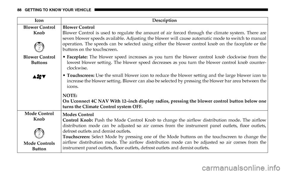
Blower Control Knob
Blower Control Buttons Blower Control
Blower Control is used to regulate the amount of air forced through the climate system. There are
seven blower speeds available. Adjusting the blower will cause automatic mode to switch to manual
operation. The speeds can be selected using either the blower control knob on the faceplate or the
buttons on the touchscreen.
•
Faceplate: The blower speed increases as you turn the blower control knob clockwise from the
lowest blower setting. The blower speed decreases as you turn the blower control knob counter -
clockwise.
• Touchscreen: Use the small blower icon to reduce the blower setting and the large blower icon to
increase the blower setting. Blower can also be selected by pressing the blower bar area between the
icons.
NOTE:
On Uconnect 4C NAV With 12–inch display radios, pressing the blower control button below one
turns the Climate Control system OFF.
Mode Control Knob
Mode Controls Button Modes Control
Control Knob:
Push the Mode Control Knob to change the airflow distribution mode. The airflow
distribution mode can be adjusted so air comes from the instrument panel outlets, floor outlets,
defrost outlets and demist outlets.
Touchscreen: Select Mode by pressing one of the Mode buttons on the touchscreen to change the
airflow distribution mode. The airflow distribution mode can be adjusted so air comes from the
instrument panel outlets, floor outlets, defrost outlets and demist outlets.
Icon
Description
Page 138 of 696

136 GETTING TO KNOW YOUR VEHICLE
RamBox Light Switch
Cargo bins feature two removable drain plugs (to allow
water to drain from bins). To remove plug, pull up on the
edge. To install push plug downward into drain hole.
NOTE:
Provisions are provided in the bins for cargo dividers and
shelf supports. These accessories (in addition to other
RamBox accessories) are available from Mopar. Locking And Unlocking RamBox
Push and release the lock or unlock button on the key fob to
lock and unlock all doors, the tailgate and the RamBox (if
equipped). Refer to “Keys” in “Getting To Know Your
Vehicle” for further details. The RamBox storage bins can be
locked using the vehicle key. To lock and unlock the storage
bin, insert the key into the keyhole on the push button and
turn clockwise to lock or counterclockwise to unlock.
Always return the key to the upright (vertical) position
before removing the key from the push button.CAUTION!
• Ensure cargo bin lids are closed and latched before moving or driving vehicle.
• Loads applied to the top of the bin lid should be mini -
mized to prevent damage to the lid and latching/
hinging mechanisms.
• Damage to the RamBox bin may occur due to heavy/ sharp objects placed in bin that shift due to vehicle
motion. In order to minimize potential for damage,
secure all cargo to prevent movement and protect inside
surfaces of bin from heavy/sharp objects with appro -
priate padding.
Page 145 of 696

GETTING TO KNOW YOUR VEHICLE 143
To move the cleat to any position on the rail, turn the nut
counterclockwise, approximately three turns. Then pull out
on the cleat and slide it to the detent nearest the desired loca-
tion. Make sure the cleat is seated in the detent and tighten
the nut.
Adjustable Cleat Assembly To remove the cleats from the utility rail, remove the end cap
screw located in the center of the end cap, using a #T30 Torx
head driver. Remove the end cap and slide the cleat off the
end of the rail.
Utility Rail End Cap
1 — Utility Rail Detent
2 — Cleat Retainer Nut
3 — Utility Rail Cleat
2