Page 458 of 698
CavityCartridge Fuse Micro Fuse Description
F34 –15 Amp Blue Frt & RR Ventilated Seat Motor
F35 –10 Amp Red Mod Inverter / Mtr Sunshade Sunroof / Mtr
Dual Sunroof
F36 40 Amp Green –Mod CBC 2 Exterior Light 1
F37 –– Spare
F38 –– Spare
F39 –– Spare
F40 –– Spare
F41 A&B –15 Amp Blue Lumbar Support & Pass SW / Mod Cluster
CCN
F42 –10 Amp Red Mod Transfer Case Switch Module (TCSM) /
SBW / Electric Park Brake SW / Overhead
Console (OHC) SW / E-Call / Bank 3 SW / Seat LT & RT Vent
F43 –10 Amp Red Port Diagnostics / Mod CD / Front & Rear
USB
F44 –20 Amp Yellow Radio / DCSD / Telematics Box Mod
F45 30 Amp Pink –Mod Door MUX Driver
F46 30 Amp Pink –Mod Door MUX Passenger
F47 –– Spare
456 IN CASE OF EMERGENCY
Page 459 of 698
CavityCartridge Fuse Micro Fuse Description
F48A 10 Amp Red –Rear View Mirror / Humidity Rain And
Light Sensor (HRLS) / SW Window Passen- ger / Rear USB / Wireless Charging Pad Mod
F49 –15 Amp Blue Mod CVPM / SNSR Blind Spot / HDLP
Adaptive Front Lighting Sensor (AFLS)
F50A –10 Amp Red Battery PACK Control Mod
F51 A&B –– Spare
F52 20 Amp Blue –Direct Battery Feed
F53 –15 Amp Blue Mod ICS Switch / Mod HVAC CTRL / Sw
Bank Upper / Sw EPB / Mod Control Steer- ing
F54B –20 Amp Yellow Power Outlet Center Seat
F55 25 Amp White – Upfitter
F56 30 Amp Pink –Mod Network Interface
F57 20 Amp Blue –Direct Battery Feed
F58 20 Amp Blue –Direct Battery Feed
F60 50 Amp Red – Mod Inverter
F61 –– Spare
7
IN CASE OF EMERGENCY 457
Page 477 of 698

Preparations For Jump Start
The battery in your vehicle is located in the front of the
engine compartment, behind the left headlight assembly.
NOTE:The positive battery post may be covered with a
protective cap if equipped. Lift up on the cap to gain access
to the positive battery post. Do not jump off fuses. Only
jump directly off positive post which has a positive (+)
symbol on or around the post.
WARNING!
• Take care to avoid the radiator cooling fan whenever
the hood is raised. It can start anytime the ignition
switch is ON. You can be injured by moving fan
blades.
• Remove any metal jewelry such as rings, watch
bands and bracelets that could make an inadvertent
electrical contact. You could be seriously injured.
• Batteries contain sulfuric acid that can burn your
skin or eyes and generate hydrogen gas which is
flammable and explosive. Keep open flames or
sparks away from the battery.
1. Apply the parking brake, shift the automatic transmis- sion into PARK and turn the ignition OFF.
2. Turn off the heater, radio, and all unnecessary electrical accessories.
3. If using another vehicle to jump start the battery, park the vehicle within the jumper cables’ reach, apply the
parking brake and make sure the ignition is OFF.
Positive Battery Post
7
IN CASE OF EMERGENCY 475
Page 491 of 698

SCHEDULED SERVICING
Your vehicle is equipped with an automatic oil change
indicator system. The oil change indicator system will
remind you that it is time to take your vehicle in for
scheduled maintenance.
Based on engine operation conditions, the oil change
indicator message will illuminate. This means that service
is required for your vehicle. Operating conditions such as
frequent short-trips, trailer tow, and extremely hot or cold
ambient temperatures will influence when the “Oil Change
Required” message is displayed. Severe Operating Condi-
tions can cause the change oil message to illuminate as
early as 3,500 miles (5,600 km) since last reset. Have your
vehicle serviced as soon as possible, within the next 500
miles (805 km).
Your authorized dealer will reset the oil change indicator
message after completing the scheduled oil change. If a
scheduled oil change is performed by someone other than
your authorized dealer, the message can be reset by
referring to the steps described under “Instrument Cluster
Display” in “Getting To Know Your Instrument Panel”.NOTE:
Under no circumstances should oil change inter-
vals exceed 10,000 miles (16,000 km), twelve months or 350
hours of engine run time, whichever comes first. The 350
hours of engine run or idle time is generally only a concern
for fleet customers.
Severe Duty All Models
NOTE: Change Engine Oil at 4,000 miles (6,500 km) or 350
hours of engine run time if the vehicle is operated in a
dusty and off road environment or is operated predomi-
nantly at idle, or only very low engine RPM’s. This type of
vehicle use is considered Severe Duty.
Once A Month Or Before A Long Trip:
• Check engine oil level.
• Check windshield washer fluid level.
• Check tire pressure and look for unusual wear or
damage. Rotate tires at the first sign of irregular wear,
even if it occurs before the oil indicator system turns on.
• Check the fluid levels of the coolant reservoir, brake
master cylinder, and fill as needed.
• Check function of all interior and exterior lights.
8
SERVICING AND MAINTENANCE 489
Page 525 of 698
 — Metric tire sizing is based on U.S.
design standards. P-Metric tires have the letter “P”
molded into the sidewall preceding the size designation.
Example: P")
Tire MarkingsNOTE:
•P (Passenger) — Metric tire sizing is based on U.S.
design standards. P-Metric tires have the letter “P”
molded into the sidewall preceding the size designation.
Example: P215/65R15 95H.
• European — Metric tire sizing is based on European
design standards. Tires designed to this standard have
the tire size molded into the sidewall beginning with the
section width. The letter �P�is absent from this tire size
designation. Example: 215/65R15 96H.
• LT (Light Truck) — Metric tire sizing is based on U.S.
design standards. The size designation for LT-Metric
tires is the same as for P-Metric tires except for the letters
“LT” that are molded into the sidewall preceding the
size designation. Example: LT235/85R16.
• Temporary spare tires are designed for temporary emer-
gency use only. Temporary high pressure compact spare
tires have the letter “T” or “S” molded into the sidewall
preceding the size designation. Example: T145/80D18
103M.
• High flotation tire sizing is based on U.S. design stan-
dards and it begins with the tire diameter molded into
the sidewall. Example: 31x10.5 R15 LT.
Tire Markings
1 — U.S. DOT Safety
Standards Code (TIN) 4 — Maximum Load
2 — Size Designation 5 — Maximum Pressure
3 — Service Description 6 — Treadwear, Traction and Temperature Grades 8
SERVICING AND MAINTENANCE 523
Page 526 of 698
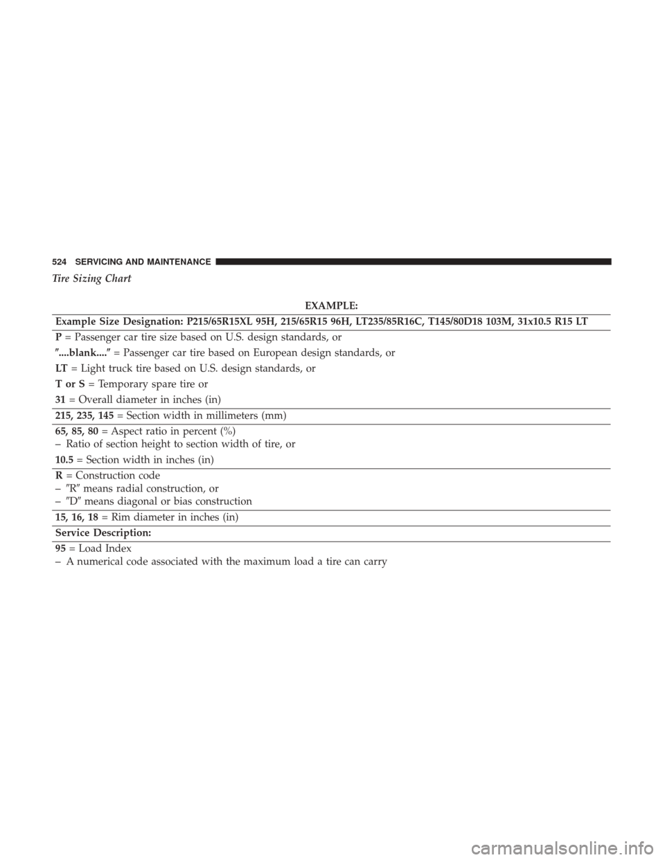
Tire Sizing Chart
EXAMPLE:
Example Size Designation: P215/65R15XL 95H, 215/65R15 96H, LT235/85R16C, T145/80D18 103M, 31x10.5 R15 LT
P = Passenger car tire size based on U.S. design standards, or
�....blank....� = Passenger car tire based on European design standards, or
LT = Light truck tire based on U.S. design standards, or
TorS= Temporary spare tire or
31 = Overall diameter in inches (in)
215, 235, 145 = Section width in millimeters (mm)
65, 85, 80 = Aspect ratio in percent (%)
–Ratio of section height to section width of tire, or
10.5 = Section width in inches (in)
R = Construction code
–�R� means radial construction, or
–�D� means diagonal or bias construction
15, 16, 18 = Rim diameter in inches (in)
Service Description:
95 = Load Index
–A numerical code associated with the maximum load a tire can carry
524 SERVICING AND MAINTENANCE
Page 527 of 698
EXAMPLE:
H = Speed Symbol
–A symbol indicating the range of speeds at which a tire can carry a load corresponding to its load index under cer-
tain operating conditions
–The maximum speed corresponding to the speed symbol should only be achieved under specified operating condi-
tions (i.e., tire pressure, vehicle loading, road conditions, and posted speed limits)
Load Identification:
Absence of the following load identification symbols on the sidewall of the tire indicates a Standard Load (SL) tire:
• XL = Extra load (or reinforced) tire, or
• LL = Light load tire or
• C, D, E, F, G = Load range associated with the maximum load a tire can carry at a specified pressure
Maximum Load – Maximum load indicates the maximum load this tire is designed to carry
Maximum Pressure – Maximum pressure indicates the maximum permissible cold tire inflation pressure for this tire8
SERVICING AND MAINTENANCE 525
Page 539 of 698

WARNING!
Tires and the spare tire should be replaced after six
years, regardless of the remaining tread. Failure to
follow this warning can result in sudden tire failure.
You could lose control and have a collision resulting in
serious injury or death.
Keep dismounted tires in a cool, dry place with as little
exposure to light as possible. Protect tires from contact with
oil, grease, and gasoline.
Replacement Tires
The tires on your new vehicle provide a balance of many
characteristics. They should be inspected regularly for
wear and correct cold tire inflation pressures. The manu-
facturer strongly recommends that you use tires equivalent
to the originals in size, quality and performance when
replacement is needed. Refer to the paragraph on “Tread
Wear Indicators” in this section. Refer to the Tire and
Loading Information placard or the Vehicle Certification
Label for the size designation of your tire. The Load Index
and Speed Symbol for your tire will be found on the
original equipment tire sidewall. See the Tire Sizing Chart example found in the “Tire Safety
Information” section of this manual for more information
relating to the Load Index and Speed Symbol of a tire.
It is recommended to replace the two front tires or two rear
tires as a pair. Replacing just one tire can seriously affect
your vehicle’s handling. If you ever replace a wheel, make
sure that the wheel’s specifications match those of the
original wheels.
It is recommended you contact an authorized tire dealer or
original equipment dealer with any questions you may
have on tire specifications or capability. Failure to use
equivalent replacement tires may adversely affect the
safety, handling, and ride of your vehicle.
WARNING!
•
Do not use a tire, wheel size, load rating, or speed
rating other than that specified for your vehicle.
Some combinations of unapproved tires and wheels
may change suspension dimensions and perfor-
mance characteristics, resulting in changes to steer-
ing, handling, and braking of your vehicle. This can
cause unpredictable handling and stress to steering
(Continued)
8
SERVICING AND MAINTENANCE 537

 / SW Window Passen- ger / Rear USB / Wireless Charging Pad Mod
F49 –15 Amp Blu")