Page 166 of 312

164
Maintenance
recommendations
In bad or wintry weather, ensure that the
camera is not covered by mud, frost or snow.
Check the cleanliness of the camera lens
regularly.
If necessary, clean the camera with a soft, dry
cloth.
When washing the vehicle using a high-
pressure jet, keep the spray directed at least
30 cm away from the camera.
Surround Rear Vision
With the ignition on, in order to improve
visibility of the passenger side blind spot and
the rear of the vehicle, this system uses two
cameras to display the views of the vehicle’s
close surroundings on the output screen (if it is
a panel van or has a solid partition).
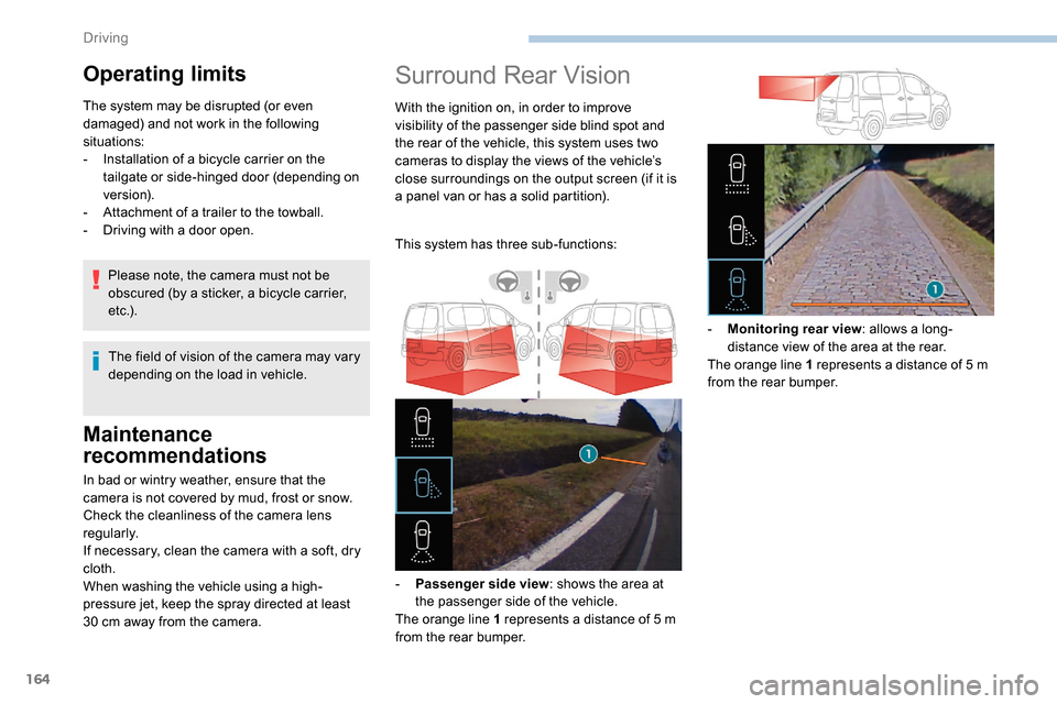
This system has three sub-functions:
-
P
assenger side view : shows the area at
the passenger side of the vehicle.
The orange line 1 represents a distance of 5
m
from the rear bumper. -
M
onitoring rear view: allows a long-
distance view of the area at the rear.
The orange line 1 represents a distance of 5
m
from the rear bumper.
Operating limits
The system may be disrupted (or even
damaged) and not work in the following
situations:
-
I
nstallation of a bicycle carrier on the
tailgate or side-hinged door (depending on
ve r s i o n).
-
A
ttachment of a trailer to the towball.
-
D
riving with a door open.
The field of vision of the camera may vary
depending on the load in vehicle.
Please note, the camera must not be
obscured (by a sticker, a bicycle carrier,
e t c .) .
Driving
Page 168 of 312

166
Operating limits
The system may be disrupted (or even
damaged) and not work in the following
situations:
-
I
nstallation of a bicycle carrier on the
tailgate or side-hinged door (depending on
ve r s i o n).
-
A
ttachment of a trailer to the towball.
-
D
riving with a door open.
Please note, the cameras must not be
obscured (by a sticker, a bicycle carrier,
e t c .) .
The field of vision of the rear camera
( monitoring rear view and visual
reversing aid ) may vary depending on the
load in the vehicle.
If the side-hinged door is opened during
use of the monitoring rear view or the
visual reversing aid, in for ward gear or
reverse gear, the output screen becomes
grey.
If the front passenger door is opened
during use of the passenger side view ,
in for ward gear or reverse gear, the output
screen becomes grey.
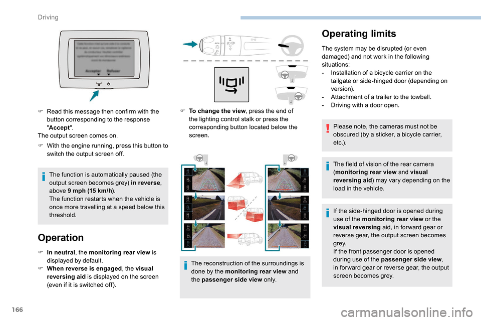
F
T
o change the view , press the end of
the lighting control stalk or press the
corresponding button located below the
screen.
The reconstruction of the surroundings is
done by the monitoring rear view and
the passenger side view o n l y.
F
W
ith the engine running, press this button to
switch the output screen off.
The function is automatically paused (the
output screen becomes grey) in reverse ,
above 9
mph (15
km/h) .
The function restarts when the vehicle is
once more travelling at a speed below this
threshold.
Operation
F In neutral , the monitoring rear view is
displayed by default.
F
W
hen reverse is engaged , the visual
reversing aid is displayed on the screen
(even if it is switched off).
F
R
ead this message then confirm with the
button corresponding to the response
" Accept ".
The output screen comes on.
Driving
Page 194 of 312

192
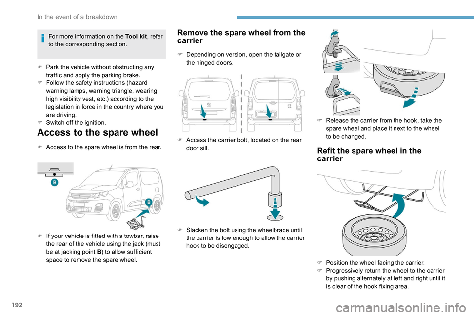
Access to the spare wheel
F Access to the spare wheel is from the rear.
F
I
f your vehicle is fitted with a towbar, raise
the rear of the vehicle using the jack (must
be at jacking point B ) to allow sufficient
space to remove the spare wheel.
Remove the spare wheel from the
carrier
F Depending on version, open the tailgate or the hinged doors.
F
A
ccess the carrier bolt, located on the rear
door sill.
F
S
lacken the bolt using the wheelbrace until
the carrier is low enough to allow the carrier
hook to be disengaged. F
R
elease the carrier from the hook, take the
spare wheel and place it next to the wheel
to be changed.
Refit the spare wheel in the
carrier
F Position the wheel facing the carrier.
F P rogressively return the wheel to the carrier
by pushing alternately at left and right until it
is clear of the hook fixing area.
For more information on the Tool kit
, refer
to the corresponding section.
F
P
ark the vehicle without obstructing any
traffic and apply the parking brake.
F
F
ollow the safety instructions (hazard
warning lamps, warning triangle, wearing
high visibility vest, etc.) according to the
legislation in force in the country where you
are driving.
F
S
witch off the ignition.
In the event of a breakdown
Page 201 of 312
199
Front foglamps
Ty p e D, H11
Rear lamps
For more information on Changing a bulb
and, in particular, the types of bulb, refer to the
corresponding section.
With side-hinged doors/tailgate
1. Brake lamps/sidelamps.
Ty p e
B, P21/5W
2. Direction indicators.
Ty p e
B, PY21W (amber)
3. Reversing lamps.
Ty p e
B, P21W
4. Foglamps.
Ty p e
B, P21W
F
F
rom the inside, disconnect the electrical
connector at the rear of the lamps.
F
I
nsert a flat screwdriver between the lamp
and the cover.
F
P
ull and lever to unclip the cover.
F Remove the two fastening screws of the module.
F
R emove the module from its housing.
F Press the locking clip and disconnect the connector.
F
T
urn the bulb holder a quarter turn anti-
clockwise.
F
R
emove the bulb holder.
F
R
eplace the faulty bulb.
To refit, carry out these operations in reverse
o r d e r.
To replace this type of bulb, you can also
contact a PEUGEOT dealer or a qualified
workshop.
8
In the event of a breakdown
Page 202 of 312

200
Take care to reposition the tabs and the supply
wire correctly to avoid trapping the wire.
After changing a rear direction
indicator bulb, the reinitialisation time is
approximately 2
minutes or more.
Number plate lamps
Ty p e A, W5W -5W
F
R
emove the two fixing bolts using the Torx
key provided in your vehicle.
For more information on the Tool kit , refer
to the corresponding section.
F
F
rom the outside, pull the whole lamp unit
towards you (with side-hinged doors )
or towards the centre of the vehicle (with
tailgate ).
F
M
ove aside the tabs, then extract the bulb
h o l d e r.
F
R
emove the faulty bulb by pressing lightly
on it, then turning it a quarter turn anti-
clockwise. F
C
hange the bulb.
To refit, carry out these operations in reverse
o r d e r.
With side-hinged doors
F Unclip the interior trim.
F D isconnect the connector by moving aside
its tab.
F
T
urn the bulb holder a quarter turn anti-
clockwise.
F
C
hange the bulb.
F
P
ut the bulb holder back in place and
reconnect the connector.
F
P
ut the trim back in place.
With tailgate
F Remove the plastic lens using a screwdriver.
F
C
hange the bulb.
F
R
efit the plastic lens and press on it.
Third brake lamp
Ty p e A , W16W -16W
F
U
nscrew the two nuts.
F
P
ush the pins.
F
I
f necessary, disconnect the connector to
remove the lamp.
F
C
hange the bulb.
In the event of a breakdown
Page 211 of 312
209
Vehicle length
Standard (L1) Long (L2)
M Useable height of the opening 1,072
N Interior load height
(varies depending on the angle of the floor and the cur ve of
the roof) 1, 20 0 to 1, 270
O Loading sill height Standard version
548 to 588 X
Standard version with increased
payload 568 to 578 561 to 565
Commercial vehicle version 602 to 610 605 to 610
P Useable width of
the opening Without Multi-Flex bench seat
675
With Multi-Flex bench seat 6 41
Q Loading sill height Standard version
534 to 558
Standard version with increased
payload 551 to 558 543 to 552
Commercial vehicle version 574 to 581 575 to 587Vehicle length
Standard (L1) Long (L2)
I Interior width between wheel arches 1, 2 2 9
J Maximum interior
width Without sliding side door
1,73 3
With 1 sliding side door 1,6 3 0
With 2 sliding side doors 1,527
K Useable height of
the opening With side-hinged doors
1,13 7
With tailgate 1,1 9 7
L Useable width of the opening 1, 242
9
Technical data