Page 608 of 682

3. Clean the area around the stage 1 fuelfilter.
4. Drain the fuel filter housing. For addi- tional information, refer to “Draining
water” in this section.
5. Close the water-in-fuel drain.
6. Disconnect the wiring harness
�Afrom
the water-in-fuel sensor.
7. Remove the fuel filter housing (Stage 1) protector
�Bfrom the module�C.
NOTE:
- It may be necessary to use a screw-
driver in the slots provided to remove the
fuel filter element from the housing.
- If fuel filter element does not release
with housing remove the element by
twisting and pulling directly away from
module simultaneously. Do not bend or
exert a side force as that may damage
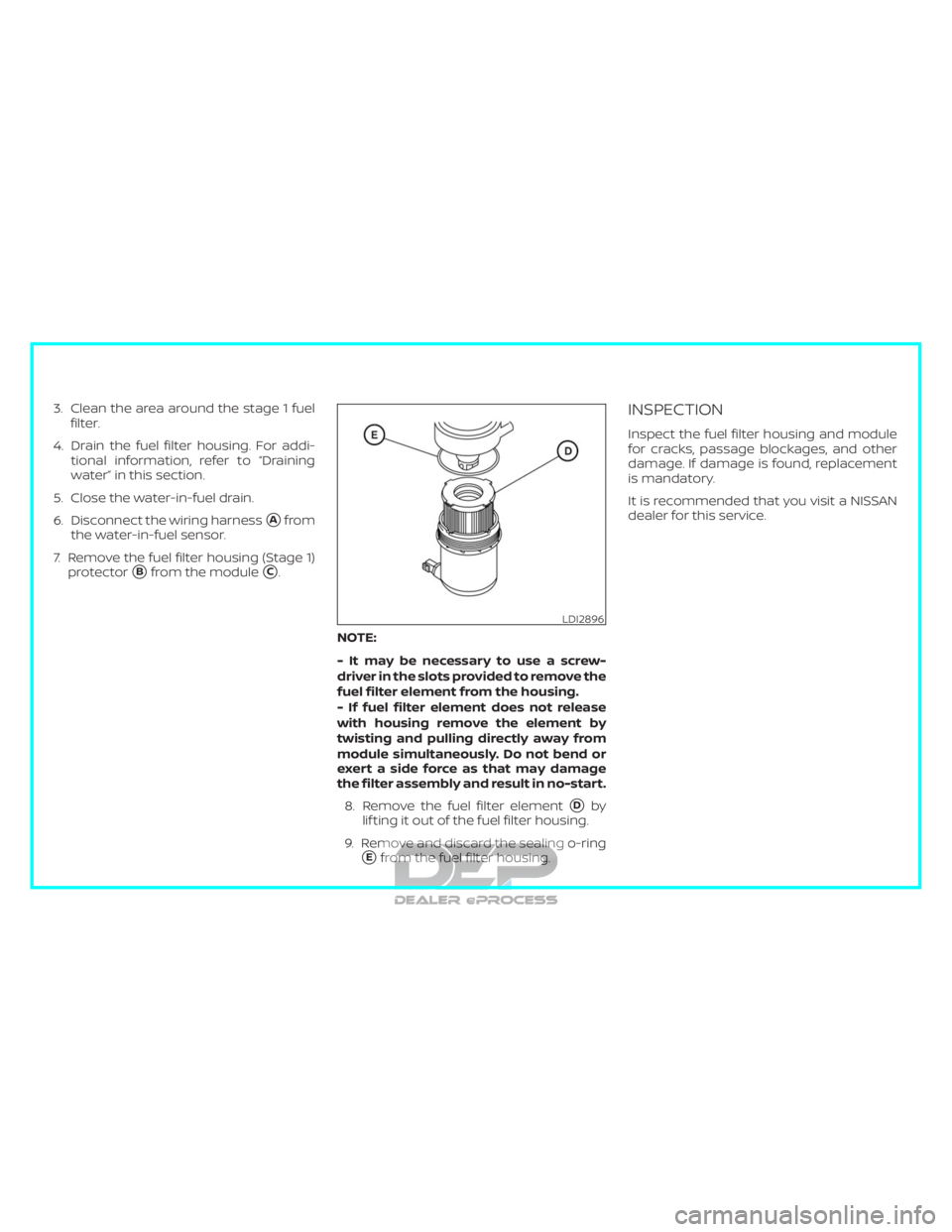
the filter assembly and result in no-start.8. Remove the fuel filter element
�Dby
lif ting it out of the fuel filter housing.
9. Remove and discard the sealing o-ring
�Efrom the fuel filter housing.
INSPECTION
Inspect the fuel filter housing and module
for cracks, passage blockages, and other
damage. If damage is found, replacement
is mandatory.
It is recommended that you visit a NISSAN
dealer for this service.
LDI2896
Page 610 of 682
15. Connect the wiring harness to thewater-in-fuel sensor.
16. Reinstall the fuel filter housing (stage 1) protector.
17. Connect the lef t and right side batter- ies.
18. Prime the fuel system. For additional information, refer to “Fuel system prim-
ing” in this section.
FUEL FILTER REPLACEMENT (stage
2)
NOTE:
∙ It is possible the “Low Fuel Pressure:
See Owner’s Manual” message will
display on the vehicle information
display af ter fuel filter replacement
due to air being introduced into the
fuel system.
LDI2891LDI2893
Page 612 of 682

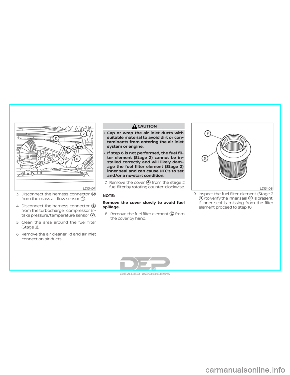
3. Disconnect the harness connector�D
from the mass air flow sensor�1.
4. Disconnect the harness connector
�E
from the turbocharger compressor in-
take pressure/temperature sensor
�2.
5. Clean the area around the fuel filter (Stage 2).
6. Remove the air cleaner lid and air inlet connection air ducts.
CAUTION
∙ Cap or wrap the air inlet ducts withsuitable material to avoid dirt or con-
taminants from entering the air inlet
system or engine.
∙ If step 6 is not performed, the fuel fil- ter element (Stage 2) cannot be in-
stalled correctly and will likely dam-
age the fuel filter element (Stage 2)
inner seal and can cause DTC’s to set
and/or a no-start condition.
7. Remove the cover
�Afrom the stage 2
fuel filter by rotating counter-clockwise.
NOTE:
Remove the cover slowly to avoid fuel
spillage. 8. Remove the fuel filter element
�Cfrom
the cover by hand. 9. Inspect the fuel filter element (Stage 2
�3) to verif y the inner seal�Fis present.
If inner seal is missing from the filter
element proceed to step 10.
LDI3407LDI3408
Page 624 of 682

The stage 1 fuel filter separates water and
filters impurities from the fuel. The stage 2
fuel filter filters finer impurities from the
diesel fuel. The stage 1 and stage 2 fuel
filters should be changed at the recom-
mended service interval or when indicated
by the information display. For additional
information, refer to “Maintenance and
schedules” and “Instruments and controls”
sections of the Titan Owner’s Manual.
The water/fuel separator should be
drained when indicated by illumination of
the water in fuel warning light.
NOTE:
Proper fuel filter maintenance and
prompt water draining when the water
in the fuel filter warning light illuminates
is essential to prevent damage to fuel
injection system components. Ignoring
the water in fuel warning light can cause
your vehicle to go into a reduced power
mode and has the potential for fuel sys-
tem damage.ENGINE PROTECTION MODE
The diesel engine in this vehicle is equipped
with electronically controlled fuel and
emission systems. Both systems monitor
engine temperatures and pressures, and
then modif y engine operation accordingly.
It is normal for the diesel engine to operate
under these modified conditions for short
durations of time. If the engine operates
under the modified conditions for ex-
tended periods of time, and the service en-
gine soon light is illuminated, have the sys-
tem checked. It is recommended that you
visit a NISSAN dealer for this service as
soon as possible.
LUBRICATION SYSTEM
It is important to change the engine oil at
the recommended service intervals to
maintain oil viscosity. Extending the oil and
filter change interval beyond the recom-
mended interval can negatively affect en-
gine performance, fuel economy and en-
gine life. For additional information, refer to
the “Do-it-yourself ” section of this manual.
GLOW PLUGS
The diesel engine glow plug system con-
sists of:∙ Eight Glow Plugs (one per cylinder)
∙ Glow Plug Control Module - Uses input from the Engine Coolant Temperature
Sensor
The glow plugs are energized momentarily
when the ignition is first turned on. The
length of time that the glow plugs are en-
ergized varies depending on engine and
environmental conditions. The required
time for the glow plugs to be energized
decreases as coolant temperature in-
creases. For additional information, refer to
the “Starting and stopping the engine” sec-
tion of this manual.
Introduction1-3