Page 477 of 682
ENGINE COMPARTMENT
WARNING
Never use a fuse of higher or lower am-
perage rating than that specified on the
fuse box cover. This could damage the
electrical system or electronic control
units or cause a fire.
If any electrical equipment does not come
on, check for an open fuse. 1. Be sure the ignition switch and the headlight switch are OFF. 2. Open the engine hood.
3. Remove the fuse box cover by pushing
the tab and lif ting the cover up.
4. Remove the fuse with the fuse puller. The fuse puller is located in the center
of the fuse block in the passenger
compartment. 5. If the fuse is open
�A, replace it with a
new fuse
�B.
6. If a new fuse also opens, have the elec- trical system checked and repaired. It is
recommended that you visit a NISSAN
dealer for this service.
VK56VD engine
LDI2962
VK56VD engine (non-XD model)
LDI3073
VK56VD engine (XD model)
LDI3074
8-24Do-it-yourself
Page 478 of 682
Fusible links
If the electrical equipment does not oper-
ate and fuses are in good condition, check
the fusible links. If any of these fusible links
are melted, replace with only Genuine
NISSAN parts.PASSENGER COMPARTMENT
WARNING
Never use a fuse of higher or lower am-
perage rating than that specified on the
fuse box cover. This could damage the
electrical system or electronic control
units or cause a fire.
If any electrical equipment does not oper-
ate, check for an open fuse. 1. Be sure the ignition switch and the headlight switch are OFF.
2. Open the glove box.
Cummins 5.0L engineLDI2882
LDI2826LDI0456
Do-it-yourself8-25
Page 479 of 682
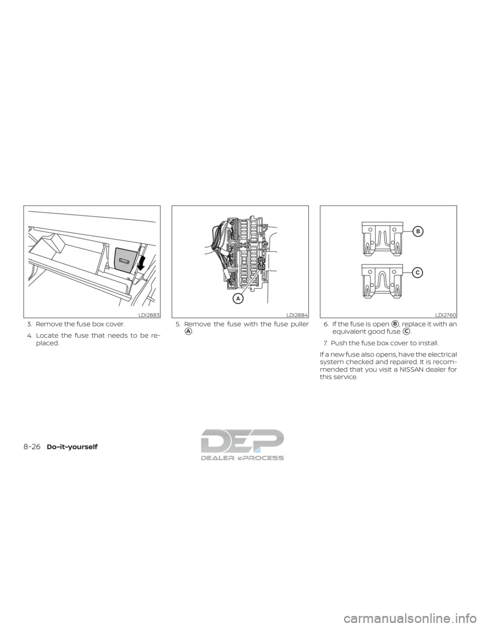
3. Remove the fuse box cover.
4. Locate the fuse that needs to be re-placed. 5. Remove the fuse with the fuse puller
�A.
6. If the fuse is open�B, replace it with an
equivalent good fuse
�C.
7. Push the fuse box cover to install.
If a new fuse also opens, have the electrical
system checked and repaired. It is recom-
mended that you visit a NISSAN dealer for
this service.
LDI2883LDI2884LDI2760
8-26Do-it-yourself
Page 594 of 682
..................1-60, 1-75
Front and rear sonar system ........5-63
Front-door pocket ...............2-71
Front power seat adjustment ........")
Front air bag system
(See supplemental restraint
system)..................1-60, 1-75
Front and rear sonar system ........5-63
Front-door pocket ...............2-71
Front power seat adjustment ........1-5
Frontseats....................1-2
Fuel Capacities and recommended
fuel/lubricants...............10-2
Fuel economy ...............5-44
Fuel gauge ..................2-9
Fueloctanerating.............10-7
Fuel recommendation ..........10-5
Loose fuel cap warning .........2-40
Fuel Cell Vehicle (FCV) System Tire pressure ................8-35
Fuelefficientdrivingtips...........5-43
Fuel-filler door .................3-27
Fuel gauge ....................2-9
Fuses .......................8-23
Fusiblelinks...................8-25
G
Garage door opener, HomeLink® Universal
Transceiver . .2-89, 2-90, 2-91, 2-92, 2-92, 2-93
Gauge Automatic transmission fluid
temperature gauge ............2-10
Engine coolant temperature gauge . .2-8
Engine oil pressure gauge .....2-10,2-11
Fuel gauge ..................2-9
Odometer ..................2-7
Speedometer ................2-7 Tachometer
.................2-8
Trip odometer ................2-7
Voltmeter ..................2-11
General maintenance .............9-2
Glovebox....................2-75
Grocery hooks .................2-81
H
Hazard warning flasher switch ........6-2
Headlightaimingcontrol ..........2-52
Headlight and turn signal switch ......2-49
Headlightcontrolswitch...........2-49
Headlights ...................8-29
Headlights,aimingcontrol..........2-52
Headrestraints................ .1-10
Heatedrearseats...............2-57
Heatedseats..................2-56
Heated steering wheel switch .......2-59
Heater Heater and air conditioner (automatic)
(if so equipped) ..............4-38
Heater and air conditioner controls . .4-39
Heater operation ..........4-31, 4-40
Heater and air conditioner (automatic) . .4-38
Hill descent control switch ..........2-61
Hill descent control system .........5-61
Hill start assist system ............5-62
HomeLink® Universal Transceiver . .2-89, 2-90, 2-91, 2-92, 2-92, 2-93
Hood .......................3-27
Hook Luggage hook ...............2-82
Horn.......................2-54 I
Ignition switch Push-button ignition switch .......5-11
Immobilizer system ..........2-44,5-14
Important vehicle information label . . .10-20
In-cabinmicrofilter ..............8-21
Increasing fuel economy ..........5-44
Indicator lights and audible reminders
(See warning/indicator lights and audible
reminders) .................2-17,2-23
Informationdisplay............. .2-26
Inside automatic anti-glare mirror .....3-34
Instrument brightness control .......2-53
Instrument panel .............0-8,2-4
Instrument paneldimmer
switch.....2-53
Intelligent Around View Monitor .......4-11
Intelligent Key system Key operating range ............3-12
Key operation ................3-13
Mechanical key ...............3-4
Remote keyless entry operation ....3-16
Troubleshooting guide ..........3-22
Warning signals ..............3-22
Interiorlight...................2-87
ISOFIX child restraints .............1-29
J
Jumpstarting..............6-14,8-18
K
Key.........................3-2
11-3
Page 648 of 682

WARNING
Always follow the instructions below.
Failure to do so could result in damage
to the charging system and cause per-
sonal injury.1. If the booster battery is in another ve- hicle, position the two vehicles to bring
their batteries near each other.
Do not allow the two vehicles to
touch. 2. Apply the parking brake. Move the shif t
lever to P (Park). Switch off all unneces-
sary electrical systems (lights, heater,
air conditioner, etc.).
3. Ensure the vent caps are level and tight.
4. Remove the fuse/fusible link box and connect jumper cables in the se-
quence illustrated (
�A,�B,�C,�D).
CAUTION
∙ Always connect positive (�) to posi-tive ( �) and negative (�) to body
ground (for example, strut mounting
bolt, engine lif t bracket, etc.) — not to
the battery.
∙ Make sure the jumper cables do not touch moving parts in the engine
compartment and that the cable
clamps do not contact any other
metal.
5. Start the engine of the booster vehicle and let it run for a few minutes.
6. Keep the engine speed of the booster vehicle at about 2,000 rpm, and start
the engine of the vehicle being jump
started.
CAUTION
Do not keep the starter motor engaged
for more than 10 seconds. If the engine
does not start right away, turn the key
off and wait 3 to 4 seconds before trying
again.
7. Af ter starting the engine, carefully dis- connect the negative cable and then
the positive cable.
LCE2223
In Case of Emergency5-3
Page 655 of 682
1. Windshield-washer fluid reservoir
2. Fuse box
3. Fuse/Fusible link box
4. Engine coolant reservoir
5. Fuel filter (Stage 2)
6. Engine oil filler cap
7. Brake fluid reservoir
8. Air cleaner
9. Battery
10. Power steering fluid reservoir
11. Radiator cap
12. Engine oil dipstick
13. Drive belt location
14. Fuse/Fusible link box
15. Battery
Cummins 5.0L
LDI2870
ENGINE COMPARTMENT CHECK
LOCATIONS
7-2Do-it-yourself


6. Engine oil filler cap
7. Brake fluid reservoir
8. Air cleaner
9. Batte")