2019 NISSAN ARMADA mirror controls
[x] Cancel search: mirror controlsPage 13 of 536
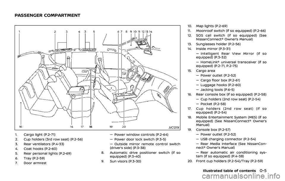
JVC1211X
1. Cargo light (P.2-71)
2. Cup holders (3rd row seat) (P.2-56)
3. Rear ventilators (P.4-33)
4. Coat hooks (P.2-60)
5. Rear personal lights (P.2-69)
6. Tray (P.2-59)
7. Door armrest— Power window controls (P.2-64)
— Power door lock switch (P.3-5)
— Outside mirror remote control switch
(driver’s side) (P.3-38)
8. Automatic drive positioner switch (if so equipped) (P.3-40)
9. Sun visors (P.3-30) 10. Map lights (P.2-69)
11. Moonroof switch (if so equipped) (P.2-66)
12. SOS call switch (if so equipped) (See
NissanConnect® Owner’s Manual)
13. Sunglasses holder (P.2-56)
14. Inside mirror (P.3-31) — Intelligent Rear View Mirror (if so
equipped) (P.3-32)
— HomeLink® universal transceiver (if so
equipped) (P.2-71, P.2-75)
15. Cargo area — Power outlet (P.2-52)
— Cargo floor box (P.2-61)
— Luggage hooks (P.2-60)
— Jacking tools (P.6-5)
16. Rear console box (if so equipped) (P.2-58) — Cup holders (2nd row seat) (P.2-54)
— Pocket (P.2-58)
17. Cup holders (2nd row seat) (if so equipped) (P.2-54)
18. Mobile Entertainment System (MES) (if so equipped) (See NissanConnect® Owner’s
Manual)
19. Console box (P.2-57) — Power outlet (P.2-52)
— USB charging connector (P.2-54)
— Rear Media Interface (See NissanCon-
nect® Owner’s Manual)
— Rear automatic air conditioning sys-
tem (if so equipped) (P.4-38)
20. Front cup holders (P.2-54)/Tray (P.2-59)
Illustrated table of contents0-5
PASSENGER COMPARTMENT
Page 95 of 536
2 Instruments and controls
Cockpit ........................................................................\
.......................... 2-3
Instrument panel ........................................................................\
.. 2-4
Meters and gauges ..................................................................... 2-5Speedometer and odometer ........................................ 2-6
Tachometer ........................................................................\
........ 2-7
Engine coolant temperature gauge ....................... 2-7
Fuel gauge ........................................................................\
........... 2-8
Engine oil pressure gauge .............................................. 2-8
Voltmeter ........................................................................\
.............. 2-9
Meter/ring illumination and needle sweep ....... 2-9
Warning lights, indicator lights and
audible reminders ..................................................................... 2-10 Checking lights ..................................................................... 2-11
Warning lights ........................................................................\
2-11
Indicator lights ...................................................................... 2-17
Audible reminders .............................................................. 2-20
Vehicle information display ............................................... 2-20 Operational indicators .................................................... 2-23
Maintenance indicators ................................................. 2-26
Trip computer ........................................................................\
2-28
Security systems ........................................................................\
2-30 Vehicle Security System ................................................ 2-30
NISSAN Vehicle Immobilizer System .................... 2-32 Wiper and washer switch ................................................... 2-33
Windshield wiper and washer operation ...... 2-34
Rain-sensing auto wiper system (if
so equipped) ........................................................................\
. 2-34
Rear window wiper and
washer operation ............................................................. 2-36
Rear window and outside mirror
(if so equipped) defroster switch ................................. 2-36
Windshield deicer switch (if so equipped) ............. 2-36
Headlight and turn signal switch ................................ 2-37 Headlight switch ............................................................... 2-37
Instrument brightness control .............................. 2-41
Turn signal switch ........................................................... 2-41
Fog light switch (if so equipped) ......................... 2-42
Heated steering wheel (if so equipped) .................. 2-42
Horn ........................................................................\
............................. 2-43
Heated seats ........................................................................\
......... 2-43 Front (if so equipped) .................................................... 2-44
Rear (if so equipped) ...................................................... 2-45
Climate controlled seats (if so equipped) ............. 2-45
Warning systems switch (if so equipped) ............. 2-46
SNOW mode switch ................................................................ 2-47
TOW mode switch .................................................................... 2-47
Vehicle Dynamic Control (VDC) OFF switch ........ 2-48
Page 130 of 536
2-36Instruments and controls
REAR WINDOW WIPER AND WASHER
OPERATION
If the rear window wiper operation is
interrupted by snow etc., the wiper may
stop moving to protect its motor. If this
occurs, turn the wiper switch to OFF and
remove the snow etc. on and around
the wiper arms. After about 1 minute,
turn the switch ON again to operate the
wiper.
The rear window wiper and washer
operate when the ignition switch is in
the ON position.
Turn the switch clockwise from the OFF
position to operate the wiper.
Intermittent (INT) — intermittent opera-
tion (not adjustable)
Low (ON) — continuous low speed opera-
tion
Push the switch forwardto operate the
washer. Then the wiper will also operate
several times.
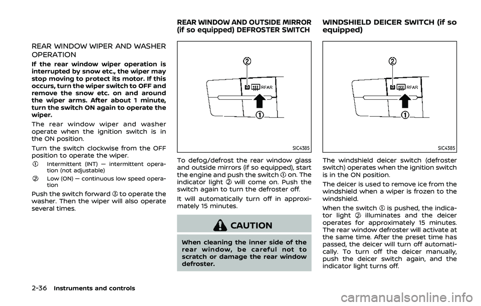
SIC4385
To defog/defrost the rear window glass
and outside mirrors (if so equipped), start
the engine and push the switch
on. The
indicator lightwill come on. Push the
switch again to turn the defroster off.
It will automatically turn off in approxi-
mately 15 minutes.
CAUTION
When cleaning the inner side of the
rear window, be careful not to
scratch or damage the rear window
defroster.
SIC4385
The windshield deicer switch (defroster
switch) operates when the ignition switch
is in the ON position.
The deicer is used to remove ice from the
windshield when a wiper is frozen to the
windshield.
When the switch
is pushed, the indica-
tor lightilluminates and the deicer
operates for approximately 15 minutes.
The rear window defroster will activate at
the same time. After the preset time has
passed, the deicer will turn off automati-
cally. To turn off the deicer manually,
push the deicer switch again, and the
indicator light turns off.
REAR WINDOW AND OUTSIDE MIRROR
(if so equipped) DEFROSTER SWITCHWINDSHIELD DEICER SWITCH (if so
equipped)
Page 134 of 536

2-40Instruments and controls
SIC2275
Headlight aiming control
Depending on the number of occupants
in the vehicle and the load it is carrying,
the headlight axis may be higher than
desired. If the vehicle is traveling on a hilly
road, the headlights may directly hit the
rearview mirror of the vehicle ahead or
the windshield of the oncoming vehicle.
The light axis can be lowered with the
operation of the switch.
The larger the number designated on the
switch, the lower the axis.
When traveling with no heavy load or on a
flat road, select position 0.
Daytime running light system
The daytime running lights automatically
illuminate when the engine is started with
the parking brake released. The daytime
running lights operate with the headlight
switch in the OFF position or in the
position. Turn the headlight switch to theposition for full illumination when
driving at night.
If the parking brake is applied before the
engine is started, the daytime running
lights do not illuminate. The daytime
running lights illuminate once the parking
brake is released. The daytime running
lights will remain on until the ignition
switch is pushed to the OFF position.
WARNING
When the daytime running light sys-
tem is active, tail lights on your
vehicle are not on. It is necessary at
dusk to turn on your headlights.
Failure to do so could cause an
accident injuring yourself and
others.
SIC3270
Page 141 of 536
traveling lane with detectable lane mar-
kers. (See “Lane Departure Warning
(LDW)/Intelligent Lane Intervention (I-LI)”
(P.5-23).)
The BSW system will turn on the side
indicator lights, located next to the out-
side mirrors, if the radar sensors detect a
vehicle in the detection zone. If the turn
signal is activated in the direction of the
detected vehicle, a chime sounds twice
and the side indicator light will flash. (See
“Blind Spot Warning (BSW)” (P.5-33).)
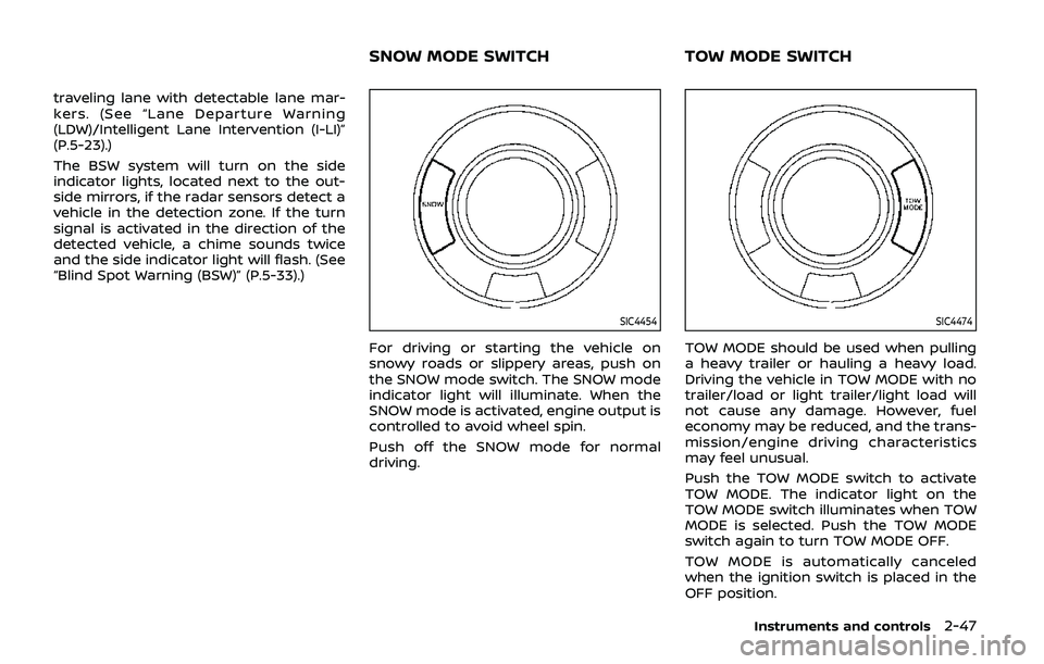
SIC4454
For driving or starting the vehicle on
snowy roads or slippery areas, push on
the SNOW mode switch. The SNOW mode
indicator light will illuminate. When the
SNOW mode is activated, engine output is
controlled to avoid wheel spin.
Push off the SNOW mode for normal
driving.
SIC4474
TOW MODE should be used when pulling
a heavy trailer or hauling a heavy load.
Driving the vehicle in TOW MODE with no
trailer/load or light trailer/light load will
not cause any damage. However, fuel
economy may be reduced, and the trans-
mission/engine driving characteristics
may feel unusual.
Push the TOW MODE switch to activate
TOW MODE. The indicator light on the
TOW MODE switch illuminates when TOW
MODE is selected. Push the TOW MODE
switch again to turn TOW MODE OFF.
TOW MODE is automatically canceled
when the ignition switch is placed in the
OFF position.
Instruments and controls2-47
SNOW MODE SWITCHTOW MODE SWITCH
Page 165 of 536

SIC4448
The light on the vanity mirror will turn on
when the cover on the vanity mirror is
opened.
When the cover is closed, the light will
turn off.
The lights will also turn off after a
period of time when the lights remain
illuminated to prevent the battery from
becoming discharged.
SIC4418
The cargo light switch has three posi-
tions: ON, centerand OFF.
ON position
When the switch is in the ON position
,
the cargo light will illuminate.
Center position
When the switch is in the center position
, the cargo light will illuminate when the
liftgate is opened.
OFF position
When the switch is in the OFF position
,
the cargo light will not illuminate. The HomeLink® Universal Transceiver
provides a convenient way to consolidate
the functions of up to three individual
hand-held transmitters into one built-in
device.
HomeLink® Universal Transceiver:
.
Will operate most Radio Frequency
(RF) devices such as garage doors,
gates, home and office lighting, entry
door locks and security systems.
. Is powered by your vehicle’s battery.
No separate batteries are required. If
the vehicle’s battery is discharged or is
disconnected, HomeLink® will retain
all programming.
When the HomeLink® Universal Trans-
ceiver is programmed, retain the origi-
nal transmitter for future programming
procedures (Example: new vehicle pur-
chases). Upon sale of the vehicle, the
programmed HomeLink® Universal
Transceiver buttons should be erased
for security purposes. For additional
information, refer to “Programming
HomeLink®” (P.2-72).WARNING
. Do not use the HomeLink® Uni-
versal Transceiver with any gar-
age door opener that lacks safety
Instruments and controls2-71
VANITY MIRROR LIGHTS CARGO LIGHTHomeLink® UNIVERSAL TRANSCEIVER
(Type A) (if so equipped)
Page 171 of 536
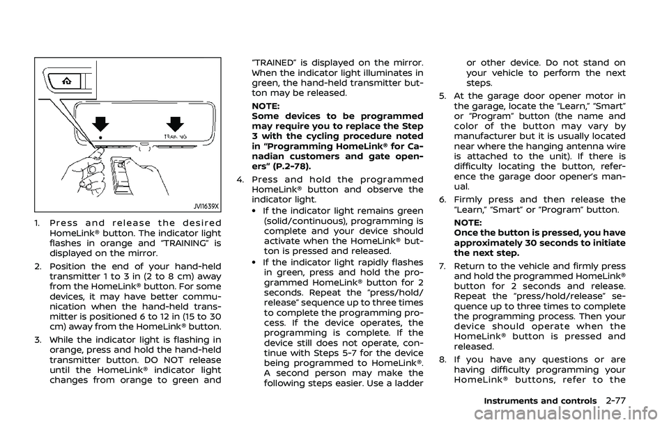
JVI1639X
1. Press and release the desiredHomeLink® button. The indicator light
flashes in orange and “TRAINING” is
displayed on the mirror.
2. Position the end of your hand-held transmitter 1 to 3 in (2 to 8 cm) away
from the HomeLink® button. For some
devices, it may have better commu-
nication when the hand-held trans-
mitter is positioned 6 to 12 in (15 to 30
cm) away from the HomeLink® button.
3. While the indicator light is flashing in orange, press and hold the hand-held
transmitter button. DO NOT release
until the HomeLink® indicator light
changes from orange to green and “TRAINED” is displayed on the mirror.
When the indicator light illuminates in
green, the hand-held transmitter but-
ton may be released.
NOTE:
Some devices to be programmed
may require you to replace the Step
3 with the cycling procedure noted
in “Programming HomeLink® for Ca-
nadian customers and gate open-
ers” (P.2-78).
4. Press and hold the programmed HomeLink® button and observe the
indicator light.
.If the indicator light remains green(solid/continuous), programming is
complete and your device should
activate when the HomeLink® but-
ton is pressed and released.
.If the indicator light rapidly flashesin green, press and hold the pro-
grammed HomeLink® button for 2
seconds. Repeat the “press/hold/
release” sequence up to three times
to complete the programming pro-
cess. If the device operates, the
programming is complete. If the
device still does not operate, con-
tinue with Steps 5-7 for the device
being programmed to HomeLink®.
A second person may make the
following steps easier. Use a ladder or other device. Do not stand on
your vehicle to perform the next
steps.
5. At the garage door opener motor in the garage, locate the “Learn,” “Smart”
or “Program” button (the name and
color of the button may vary by
manufacturer but it is usually located
near where the hanging antenna wire
is attached to the unit). If there is
difficulty locating the button, refer-
ence the garage door opener’s man-
ual.
6. Firmly press and then release the “Learn,” “Smart” or “Program” button.
NOTE:
Once the button is pressed, you have
approximately 30 seconds to initiate
the next step.
7. Return to the vehicle and firmly press and hold the programmed HomeLink®
button for 2 seconds and release.
Repeat the “press/hold/release” se-
quence up to three times to complete
the programming process. Then your
device should operate when the
HomeLink® button is pressed and
released.
8. If you have any questions or are having difficulty programming your
HomeLink® buttons, refer to the
Instruments and controls2-77
Page 172 of 536

2-78Instruments and controls
HomeLink® web site at: www.
homelink.com/nissan or call 1-800-
355-3515.
PROGRAMMING HomeLink® FOR
CANADIAN CUSTOMERS AND GATE
OPENERS
Canadian radio-frequency laws require
transmitter signals to “time-out” (or quit)
after several seconds of transmission –
which may not be long enough for
HomeLink® to pick up the signal during
programming. Similar to this Canadian
law, some U.S. gate operators are de-
signed to “time-out” in the same manner.
If you live in Canada or you are having
difficulties programming a gate operator
or garage door opener by using the
“Programming HomeLink®” procedures,
replace “Programming HomeLink®” Step
3 with the following:
NOTE:
When programming a garage door
opener, etc., unplug the device during
the “cycling” process to prevent possi-
ble damage to the device components.
Step 3: While the HomeLink® indicator
light is flashing in orange, press and
release (“cycling”) the hand-held transmit-
ter button every 2 seconds. Continue to
press and release the hand-held trans-
mitter button until the HomeLink® indi-cator light changes from orange to green.
When the indicator light illuminates in
green, hand-held transmitter button may
be released.
Proceed with “Programming HomeLink®”
step 4 to complete.
Remember to plug the device back in
when programming is completed.
OPERATING THE HomeLink® UNI-
VERSAL TRANSCEIVER
The HomeLink® Universal Transceiver,
after it is programmed, can be used to
activate the programmed device. To op-
erate, firmly press the appropriate pro-
grammed HomeLink® button. The
indicator light will illuminate in green with
three parenthesis
on the mirror
while the signal is being transmitted.
PROGRAMMING TROUBLESHOOT-
ING
If the HomeLink® does not quickly learn
the hand-held transmitter information:
. replace the hand-held transmitter
batteries with new batteries.
. position the hand-held transmitter
with its battery area facing away from
the HomeLink® button.
. press and hold the HomeLink® button
and hand-held transmitter button in
each step without interruption. .
position the hand-held transmitter 1
to 3 in (2 to 8 cm) away from the
HomeLink® button. Hold the transmit-
ter in that position for up to 15
seconds. If HomeLink® is not pro-
grammed within that time, try holding
the transmitter in another position -
for example, 6 to 12 in (15 to 30 cm)
away, keeping the HomeLink® button
in view at all times.
If you have any questions or are having
difficulty programming your HomeLink®
buttons, refer to the HomeLink® web site
at: www.homelink.com/nissan or 1-800-
355-3515.
CLEARING THE PROGRAMMED IN-
FORMATION
The following procedure clears the pro-
grammed information from three but-
tons. Individual buttons cannot be
cleared. However, individual buttons can
be reprogrammed, see “Reprogramming
a single HomeLink® button” (P.2-79).
To clear all programming
1. Press and hold the two outer HomeLink® buttons until the indicator
light begins to flash in green and
“CLEARED” is displayed on the mirror,
in approximately 10 seconds. Do not
hold for longer than 20 seconds.