2019 NISSAN ARMADA 12 volt
[x] Cancel search: 12 voltPage 17 of 536
SIC4368
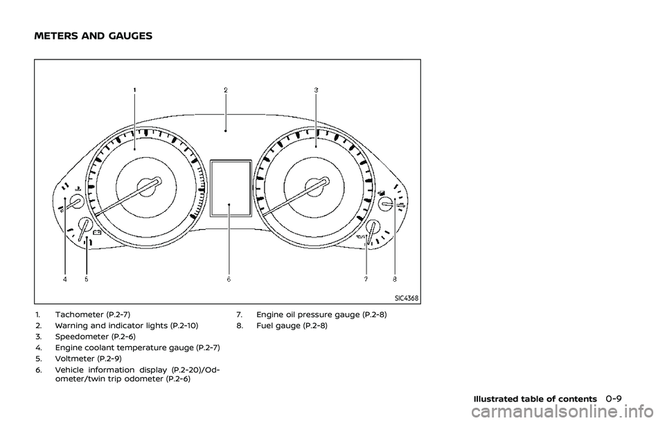
1. Tachometer (P.2-7)
2. Warning and indicator lights (P.2-10)
3. Speedometer (P.2-6)
4. Engine coolant temperature gauge (P.2-7)
5. Voltmeter (P.2-9)
6. Vehicle information display (P.2-20)/Od-ometer/twin trip odometer (P.2-6) 7. Engine oil pressure gauge (P.2-8)
8. Fuel gauge (P.2-8)
Illustrated table of contents0-9
METERS AND GAUGES
Page 95 of 536

2 Instruments and controls
Cockpit ........................................................................\
.......................... 2-3
Instrument panel ........................................................................\
.. 2-4
Meters and gauges ..................................................................... 2-5Speedometer and odometer ........................................ 2-6
Tachometer ........................................................................\
........ 2-7
Engine coolant temperature gauge ....................... 2-7
Fuel gauge ........................................................................\
........... 2-8
Engine oil pressure gauge .............................................. 2-8
Voltmeter ........................................................................\
.............. 2-9
Meter/ring illumination and needle sweep ....... 2-9
Warning lights, indicator lights and
audible reminders ..................................................................... 2-10 Checking lights ..................................................................... 2-11
Warning lights ........................................................................\
2-11
Indicator lights ...................................................................... 2-17
Audible reminders .............................................................. 2-20
Vehicle information display ............................................... 2-20 Operational indicators .................................................... 2-23
Maintenance indicators ................................................. 2-26
Trip computer ........................................................................\
2-28
Security systems ........................................................................\
2-30 Vehicle Security System ................................................ 2-30
NISSAN Vehicle Immobilizer System .................... 2-32 Wiper and washer switch ................................................... 2-33
Windshield wiper and washer operation ...... 2-34
Rain-sensing auto wiper system (if
so equipped) ........................................................................\
. 2-34
Rear window wiper and
washer operation ............................................................. 2-36
Rear window and outside mirror
(if so equipped) defroster switch ................................. 2-36
Windshield deicer switch (if so equipped) ............. 2-36
Headlight and turn signal switch ................................ 2-37 Headlight switch ............................................................... 2-37
Instrument brightness control .............................. 2-41
Turn signal switch ........................................................... 2-41
Fog light switch (if so equipped) ......................... 2-42
Heated steering wheel (if so equipped) .................. 2-42
Horn ........................................................................\
............................. 2-43
Heated seats ........................................................................\
......... 2-43 Front (if so equipped) .................................................... 2-44
Rear (if so equipped) ...................................................... 2-45
Climate controlled seats (if so equipped) ............. 2-45
Warning systems switch (if so equipped) ............. 2-46
SNOW mode switch ................................................................ 2-47
TOW mode switch .................................................................... 2-47
Vehicle Dynamic Control (VDC) OFF switch ........ 2-48
Page 99 of 536
SIC4368
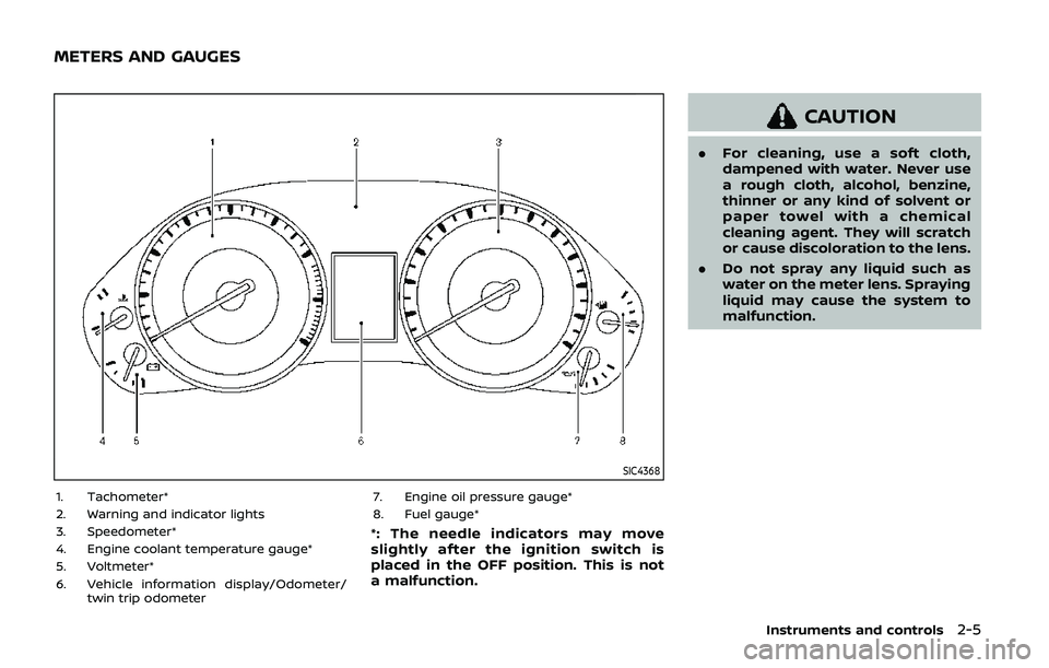
1. Tachometer*
2. Warning and indicator lights
3. Speedometer*
4. Engine coolant temperature gauge*
5. Voltmeter*
6. Vehicle information display/Odometer/twin trip odometer 7. Engine oil pressure gauge*
8. Fuel gauge*
*: The needle indicators may move
slightly after the ignition switch is
placed in the OFF position. This is not
a malfunction.
CAUTION
.
For cleaning, use a soft cloth,
dampened with water. Never use
a rough cloth, alcohol, benzine,
thinner or any kind of solvent or
paper towel with a chemical
cleaning agent. They will scratch
or cause discoloration to the lens.
. Do not spray any liquid such as
water on the meter lens. Spraying
liquid may cause the system to
malfunction.
Instruments and controls2-5
METERS AND GAUGES
Page 103 of 536

the dipstick to check the oil level.
(See “Engine oil” (P.8-6).)
. If the gauge needle does not
move with the proper amount of
engine oil, have the vehicle
checked. It is recommended you
visit a NISSAN dealer for this
service. Continued vehicle opera-
tion in such a condition could
cause serious damage to the en-
gine.
SIC4376
VOLTMETER
When the ignition switch is placed in the
ON position, the volt meter indicates the
battery voltage. When the engine is run-
ning, it indicates the generator voltage.
While cranking the engine, the volt drop
below the normal range. If the needle is
not in the normal range (10.5 to 15.5 volt)
while the engine is running, it may
indicate that the charging system is not
functioning properly. Have the system
checked. It is recommended you visit a
NISSAN dealer for this service.
METER/RING ILLUMINATION AND
NEEDLE SWEEP
The ring illumination surrounding meters
and gauges illuminates when the driver’s
door is closed after getting into the
vehicle with the Intelligent Key carried in.
When the engine is started, the indicator
needles will sweep in the speedometer
and tachometer and the ring illumination
will be brightened gradually. This function
can be turned off. (See “Trip computer”
(P.2-28).)
Instruments and controls2-9
Page 146 of 536
2-52Instruments and controls
CAUTION
.Use power outlet with the engine
running to avoid discharging the
vehicle battery.
. Avoid using power outlet when
the air conditioner, headlights or
rear window defroster is on.
. Before inserting or disconnecting
a plug, be sure the electrical
accessory being used is turned
OFF.
. When not in use, be sure to close
the cap. Do not allow water or any
liquid to contact the outlet.
SIC4389
Instrument panel
SIC4456Back side of front console
SIC4391
Luggage room
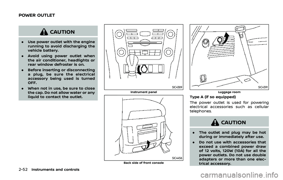
Type A (if so equipped)
The power outlet is used for powering
electrical accessories such as cellular
telephones.
CAUTION
.The outlet and plug may be hot
during or immediately after use.
. Do not use with accessories that
exceed a combined power draw
of 12 volts, 120W (10A) for all the
power outlets. Do not use double
adapters or more than one elec-
trical accessory.
POWER OUTLET
Page 147 of 536
.This power outlet is not designed
for use with a cigarette lighter
unit.
. Push the plug in as far as it will
go. If good contact is not made,
the plug may overheat or the
internal temperature fuse may
blow.
SIC2648
Main switch
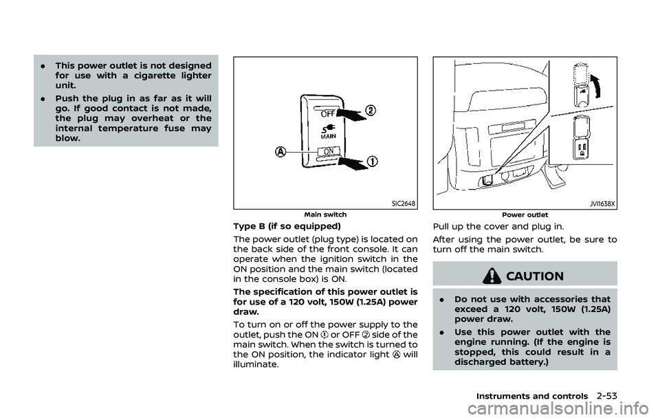
Type B (if so equipped)
The power outlet (plug type) is located on
the back side of the front console. It can
operate when the ignition switch in the
ON position and the main switch (located
in the console box) is ON.
The specification of this power outlet is
for use of a 120 volt, 150W (1.25A) power
draw.
To turn on or off the power supply to the
outlet, push the ON
or OFFside of the
main switch. When the switch is turned to
the ON position, the indicator light
will
illuminate.
JVI1638X
Power outlet
Pull up the cover and plug in.
After using the power outlet, be sure to
turn off the main switch.
CAUTION
. Do not use with accessories that
exceed a 120 volt, 150W (1.25A)
power draw.
. Use this power outlet with the
engine running. (If the engine is
stopped, this could result in a
discharged battery.)
Instruments and controls2-53
Page 148 of 536

2-54Instruments and controls
JVI1604X
USB (Universal Serial Bus) CHAR-
GING CONNECTOR
The USB connectorcan be used only
for charging an external device.
Open the cover to access the USB con-
nector.
Connect a USB device into the connector.
Charging will start automatically (max-
imum output up to 5 volt, 12W, 2.4A).
The external device will be charged con-
tinuously while the ignition switch is in
the ACC or ON position.
Some mobile devices cannot be charged
depending on their specifications.
CAUTION
. Do not force a USB device into the
connector. Inserting the USB de-
vice tilted or up-side-down into
the connector may damage the
connector. Make sure that the
USB device is connected correctly
into the connector.
. Do not use a reversible USB cable.
Using the reversible USB cable
may damage the connector.
. Do not grab the USB connector
cover when pulling the USB de-
vice out of the connector. This
could damage the connector and
the cover.
CUP HOLDERS
CAUTION
.Avoid abrupt starting and braking
when the cup holder is being
used to prevent spilling the drink.
If the liquid is hot, it can scald you
or your passenger.
. Use only soft cups in the cup
holder. Hard objects can injure
you in an accident.
. Do not recline the rear seatback
when you use the cup holders on
the rear armrest. Doing so may
cause the beverages to spill over,
and if they are hot, they may
scald the passengers.
STORAGE
Page 196 of 536
3-22Pre-driving checks and adjustments
WARNING
.Always be sure the liftgate has
been closed securely to prevent it
from opening while driving.
. Do not drive with the liftgate
open. This could allow dangerous
exhaust gases to be drawn into
the vehicle. See “Exhaust gas
(carbon monoxide)” (P.5-4).
. Do not leave children unattended
inside the vehicle. They could
unknowingly activate switches
or controls. Unattended children
could become involved in serious
accidents.
. Always be sure that hands and
feet are clear of the door frame to
avoid injury while closing the
liftgate.
JVP0464X
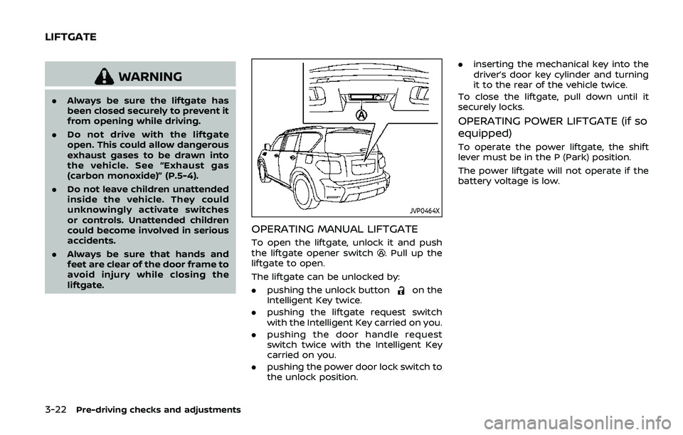
OPERATING MANUAL LIFTGATE
To open the liftgate, unlock it and push
the liftgate opener switch. Pull up the
liftgate to open.
The liftgate can be unlocked by:
. pushing the unlock button
on the
Intelligent Key twice.
. pushing the liftgate request switch
with the Intelligent Key carried on you.
. pushing the door handle request
switch twice with the Intelligent Key
carried on you.
. pushing the power door lock switch to
the unlock position. .
inserting the mechanical key into the
driver’s door key cylinder and turning
it to the rear of the vehicle twice.
To close the liftgate, pull down until it
securely locks.
OPERATING POWER LIFTGATE (if so
equipped)
To operate the power liftgate, the shift
lever must be in the P (Park) position.
The power liftgate will not operate if the
battery voltage is low.
LIFTGATE