2019 NISSAN ARMADA lights
[x] Cancel search: lightsPage 210 of 536
3-36Pre-driving checks and adjustments
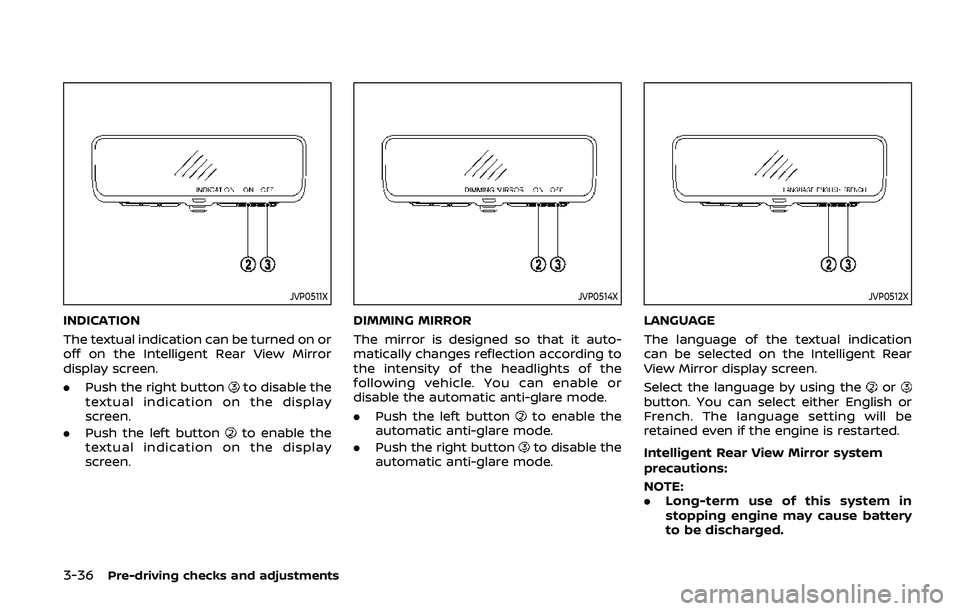
JVP0511X
INDICATION
The textual indication can be turned on or
off on the Intelligent Rear View Mirror
display screen.
.Push the right button
to disable the
textual indication on the display
screen.
. Push the left button
to enable the
textual indication on the display
screen.
JVP0514X
DIMMING MIRROR
The mirror is designed so that it auto-
matically changes reflection according to
the intensity of the headlights of the
following vehicle. You can enable or
disable the automatic anti-glare mode.
. Push the left button
to enable the
automatic anti-glare mode.
. Push the right button
to disable the
automatic anti-glare mode.
JVP0512X
LANGUAGE
The language of the textual indication
can be selected on the Intelligent Rear
View Mirror display screen.
Select the language by using the
orbutton. You can select either English or
French. The language setting will be
retained even if the engine is restarted.
Intelligent Rear View Mirror system
precautions:
NOTE:
. Long-term use of this system in
stopping engine may cause battery
to be discharged.
Page 211 of 536
.Do not attach an antenna of wireless
device near the Intelligent Rear View
Mirror. Electric wave from wireless
device may cause disturbed image
in Intelligent Rear View Mirror.
. Do not push buttons excessively or
operating the lever roughly may
cause a system failure or the Intelli-
gent Rear View Mirror itself to drop.
. Never turn the body of Intelligent
Rear View Mirror by 90° or more. It
may damage the Intelligent Rear
View Mirror.
. Do not apply strong shocks to the
body of Intelligent Rear View Mirror.
It may cause a system failure.
. Do not apply heavy load to the
camera and camera-cover on the
rear of the vehicle. It may cause the
camera to be removed or may cause
a system failure.
. If it is difficult to see the Intelligent
Rear View Mirror display screen be-
cause of a strong external light,
switch the mode to the conventional
rearview mirror mode for better use.
. Close the sunshade (if so equipped)
when the Intelligent Rear View Mir-
ror display screen is unclear due to
strong external light.
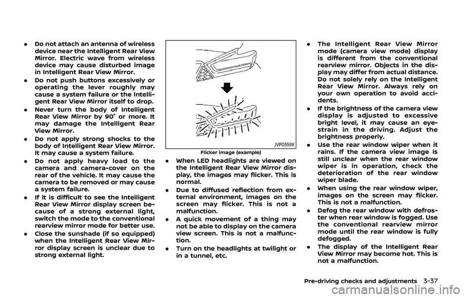
JVP0559X
Flicker image (example)
.When LED headlights are viewed on
the Intelligent Rear View Mirror dis-
play, the images may flicker. This is
normal.
. Due to diffused reflection from ex-
ternal environment, images on the
screen may flicker. This is not a
malfunction.
. A quick movement of a thing may
not be able to display on the camera
view screen. This is not a malfunc-
tion.
. Turn on the headlights at twilight or
in a tunnel, etc. .
The Intelligent Rear View Mirror
mode (camera view mode) display
is different from the conventional
rearview mirror. Objects in the dis-
play may differ from actual distance.
Do not solely rely on the Intelligent
Rear View Mirror. Always rely on
your own operation to avoid acci-
dents.
. If the brightness of the camera view
display is adjusted to excessive
bright level, it may cause an eye-
strain in the driving. Adjust the
brightness properly.
. Use the rear window wiper when it
rains. If the camera view image is
still unclear when the rear window
wiper is in operation, check the
deterioration of the rear window
wiper blade.
. When using the rear window wiper,
images on the screen may flicker.
This is not a malfunction.
. Defog the rear window with defros-
ter when rear window is fogged. Use
the conventional rearview mirror
mode until the rear window is fully
defogged.
. The display of the Intelligent Rear
View Mirror may become hot. This is
not a malfunction.
Pre-driving checks and adjustments3-37
Page 214 of 536
3-40Pre-driving checks and adjustments
3. Choose the right or left outside mirrorby operating the outside mirror con-
trol switch.
4. The outside mirror surfaces move downward.
When one of the following conditions has
occurred, the outside mirror surfaces will
return to their original positions.
. The shift lever is moved to any posi-
tion other than R (Reverse).
. The outside mirror control switch is
set to the center position.
. The ignition switch is placed in the
OFF position.
Automatic anti-glare (if so
equipped)
The outside rearview mirrors are de-
signed so that its automatically change
reflection according to the intensity of
the headlights of the vehicle following
you.
The anti-glare system will be automati-
cally turned on when the ignition switch is
placed in the ON position.
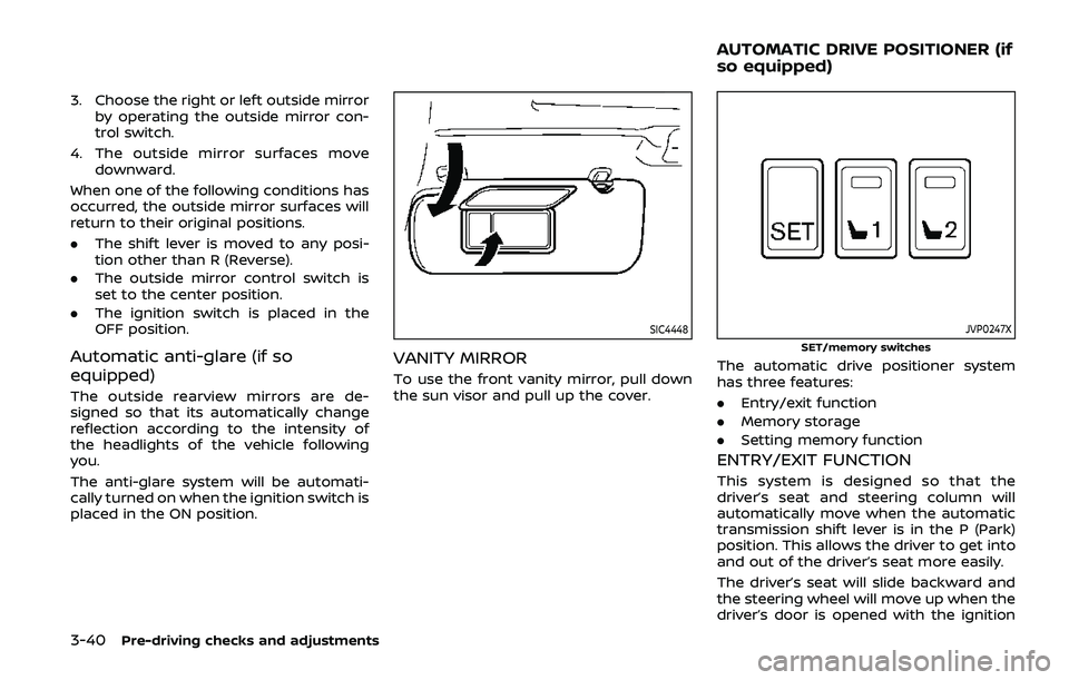
SIC4448
VANITY MIRROR
To use the front vanity mirror, pull down
the sun visor and pull up the cover.
JVP0247X
SET/memory switches
The automatic drive positioner system
has three features:
.Entry/exit function
. Memory storage
. Setting memory function
ENTRY/EXIT FUNCTION
This system is designed so that the
driver’s seat and steering column will
automatically move when the automatic
transmission shift lever is in the P (Park)
position. This allows the driver to get into
and out of the driver’s seat more easily.
The driver’s seat will slide backward and
the steering wheel will move up when the
driver’s door is opened with the ignition
AUTOMATIC DRIVE POSITIONER (if
so equipped)
Page 252 of 536
4-36Monitor, heater, air conditioner, audio, phone and voice recognition systems
4. To turn off the heater and air condi-tioner system, push the “OFF” button.
A visible mist may be seen coming from
the ventilators in hot, humid conditions as
the air is cooled rapidly. This does not
indicate a malfunction.
Dehumidified defrosting or defogging:
1. Push the “
” front defroster button.
(The indicator light on the button will
illuminate.)
2. Turn the temperature control dial to set the desired temperature.
. To quickly remove ice from the out-
side of the windows, push the fan
speed increase button “
” and set it
to the maximum position.
. As soon as possible after the wind-
shield is clean, push the “AUTO” button
to return to the auto mode.
. When the “
” front defroster button
is pushed, the air conditioner will
automatically be turned on at outside
temperatures above 23°F (−5°C) to
defog the windshield, and the air
recirculate mode will automatically
be turned off.
Outside air is drawn into the passen-
ger compartment to improve the
defogging performance.
Manual operation
Fan speed control:
Push the fan speed increase “
”or
decrease “” buttons to manually con-
trol the fan speed.
Push the “AUTO” button to return to
automatic control of the fan speed.
Temperature control:
Turn the temperature control dial to set
the desired temperature.
Air flow control:
Pushing the “MODE” manual air flow
control button selects the air outlet to:
: Air flows from center and side ventila-
tors.
: Air flows from center and side ventila-tors and foot outlets.
: Air flows mainly from foot outlets.
: Air flows from defroster and foot outlets.
Air intake control:
. Push the “
” air recirculation button
to recirculate interior air inside the
vehicle. The “
” indicator light on the
button will come on. The air recircula-
tion mode cannot be activated when
the air conditioner is in the front
defrosting mode “
”. .
Push the “
” outside air circulation
button to draw outside air into the
passenger compartment. The “
”
indicator light on the button will come
on.
. To control the air intake automatically,
push and hold either the “
” air
recirculation button or the “” out-
side air circulation button (whichever
indicator light is illuminated). The
indicator lights (both air recirculation
and outside air circulation buttons)
will flash twice, and then the air intake
will switch to automatic control.
Turning the system off
Push the OFF button.
Upper vent system
When the upper vent “” button is
pushed, the air flow against the driver’s
or passenger’s upper body becomes gen-
tle. The indicator light on the button will
illuminate.
In this mode, air from the upper ventilator
flows in order to control the cabin tem-
perature without blowing air directly on
the occupants.
Push the upper vent “
” button when
you want the air conditioner to work
quickly.
To turn the system off, push the upper
Page 274 of 536
5-14Starting and driving
moved to the P (Park) position.
When the ignition switch cannot be
pushed toward the LOCK position, pro-
ceed as follows:
1. Move the shift lever into the P (Park)position.
2. Push the ignition switch to the OFF position. The ignition switch position
indicator will not illuminate.
3. Open the door. The ignition switch will change to the LOCK position.
The shift lever can be moved from the P
(Park) position if the ignition switch is in
the ON position and the brake pedal is
depressed.
If the battery of the vehicle is dis-
charged, the push-button ignition
switch cannot be turned from the LOCK
position.
Some indicators and warnings for opera-
tion are displayed on the vehicle informa-
tion display between the speedometer
and tachometer. (See “Vehicle informa-
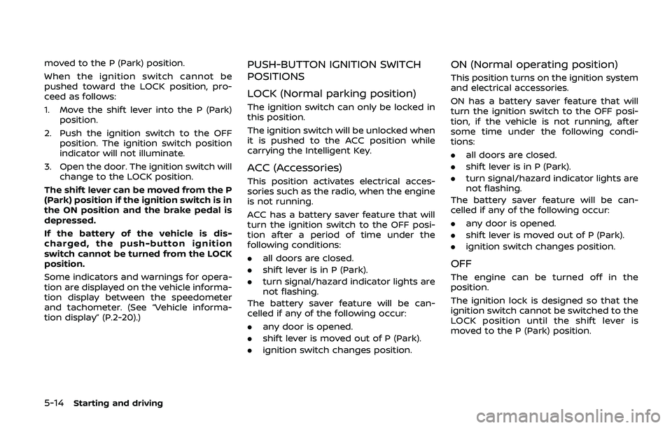
tion display” (P.2-20).)PUSH-BUTTON IGNITION SWITCH
POSITIONS
LOCK (Normal parking position)
The ignition switch can only be locked in
this position.
The ignition switch will be unlocked when
it is pushed to the ACC position while
carrying the Intelligent Key.
ACC (Accessories)
This position activates electrical acces-
sories such as the radio, when the engine
is not running.
ACC has a battery saver feature that will
turn the ignition switch to the OFF posi-
tion after a period of time under the
following conditions:
. all doors are closed.
. shift lever is in P (Park).
. turn signal/hazard indicator lights are
not flashing.
The battery saver feature will be can-
celled if any of the following occur:
. any door is opened.
. shift lever is moved out of P (Park).
. ignition switch changes position.
ON (Normal operating position)
This position turns on the ignition system
and electrical accessories.
ON has a battery saver feature that will
turn the ignition switch to the OFF posi-
tion, if the vehicle is not running, after
some time under the following condi-
tions:
.all doors are closed.
. shift lever is in P (Park).
. turn signal/hazard indicator lights are
not flashing.
The battery saver feature will be can-
celled if any of the following occur:
. any door is opened.
. shift lever is moved out of P (Park).
. ignition switch changes position.
OFF
The engine can be turned off in the
position.
The ignition lock is designed so that the
ignition switch cannot be switched to the
LOCK position until the shift lever is
moved to the P (Park) position.
Page 276 of 536
5-16Starting and driving
.Make sure the area around the vehicle
is clear.
. Check fluid levels such as engine oil,
coolant, brake fluid and window
washer fluid as frequently as possible,
or at least whenever you refuel.
. Check that all windows and lights are
clean.
. Visually inspect tires for their appear-
ance and condition. Also check tires
for proper inflation.
. Lock all doors.
. Position seat and adjust head re-
straints/headrests.
. Adjust inside and outside mirrors.
. Fasten seat belts and ask all passen-
gers to do likewise.
. Check the operation of warning lights
when the ignition switch is pushed to
the ON position. (See “Warning lights,
indicator lights and audible remin-
ders” (P.2-10).) 1. Apply the parking brake.
2. Move the shift lever to the P (Park) or N
(Neutral) position. (P is recommended.)
The starter is designed not to operate
unless the shift lever is in either of the
above positions.
3. Push the ignition switch to the ON position. Firmly depress the brake
pedal and push the ignition switch to
start the engine.
To start the engine immediately, push
and release the ignition switch while
depressing the brake pedal with the
ignition switch in any position.
.If the engine is very hard to start inextremely cold weather or when
restarting, depress the accelerator
pedal a little (approximately 1/3 to
the floor) and while holding, crank
the engine. Release the accelerator
pedal when the engine starts.
.If the engine is very hard to startbecause it is flooded, depress the
accelerator pedal all the way to the
floor and hold it. Push the ignition
switch to the ON position to start
cranking the engine. After 5 or 6
seconds, stop cranking by pushing
the ignition switch to OFF. After
cranking the engine, release the
accelerator pedal. Crank the engine
with your foot off the accelerator pedal
by depressing the brake
pedal and pushing the push-button
ignition switch to start the engine.
If the engine starts, but fails to run,
repeat the above procedure.
CAUTION
Do not operate the starter for more
than 15 seconds at a time. If the
engine does not start, push the
ignition switch to OFF and wait 10
seconds before cranking again,
otherwise the starter could be da-
maged.
4. Warm-up
Allow the engine to idle for at least 30
seconds after starting. Do not race the
engine while warming it up. Drive at
moderate speed for a short distance
first, especially in cold weather. In cold
weather, keep the engine running for
a minimum of 2 - 3 minutes before
shutting it off. Starting and stopping
the engine over a short period of time
may make the vehicle more difficult to
start.
When racing the engine up to 4,000
rpm or more under the no load
condition, the engine will enter the
BEFORE STARTING THE ENGINE STARTING THE ENGINE
Page 278 of 536
5-18Starting and driving
If:
1. The engine coolant temperature is notreduced.
2. The air conditioning cooling function does not turn back ON.
3. The engine oil pressure warning light
illuminates or engine coolant
temperature gauge does not return
to the normal range from the H
position, this may indicate a malfunc-
tion. Move the vehicle off the road to a
safe area and allow the engine to cool.
If after checking the oil and coolant,
the
remains on or engine coolant
temperature does not return to the
normal range, do not continue to
drive. It is recommended you contact
a NISSAN dealer.
The Malfunction Indicator Light (MIL)
may also come ON. You do not need to
have your vehicle towed, unless it re-
mains on, but have it inspected soon. It is
recommended you contact a NISSAN
dealer for this service. See “Warning lights,
indicator lights and audible reminders”
(P.2-10).
WARNING
Overheating can result in reduced
engine power and vehicle speed.
The reduced speed may be lower
than other traffic, which could in-
crease the chance of a collision. Be
especially careful when driving. If the
vehicle cannot maintain a safe driv-
ing speed, pull to the side of the road
in a safe area. Allow the engine to
cool and return to normal operation.
See “If your vehicle overheats” (P.6-
14).
CAUTION
Running the engine with the engine
oil pressure warning light on could
cause serious damage to the engine
almost immediately. Such damage is
not covered by warranty. Turn off the
engine as soon as it is safe to do so.
AUTOMATIC TRANSMISSION
7 speed automatic transmission
The automatic transmission in your vehi-
cle is electronically controlled by a trans-
mission control module to produce
maximum efficiency and smooth opera-
tion.
Shown on the following pages are the
recommended operating procedures for
this transmission. Follow these proce-
dures for maximum vehicle performance
and driving enjoyment.
Starting the vehicle
After starting the engine, fully depress the
foot brake pedal and push the shift lever
button before shifting the shift lever to
the R (Reverse), N (Neutral), D (Drive) or
Manual shift mode position. Be sure the
vehicle is fully stopped before attempting
to shift the shift lever.
This automatic transmission model is
designed so that the foot brake pedal
must be depressed before shifting from
P (Park) to any drive position while the
ignition switch position is ON.
The shift lever cannot be moved out of
the P (Park) position and into any of the
other gear positions if the ignition
switch is pushed to the LOCK, OFF or
ACC position.
Page 290 of 536

5-30Starting and driving
water, dirt, snow, etc.
— On roads where the discontin- ued lane markers are still
detectable.
— On roads where there are sharp curves.
— On roads where there are sharply contrasting objects,
such as shadows, snow,
water, wheel ruts, seams or
lines remaining after road re-
pairs. (The LDW and I-LI sys-
tems could detect these items
as lane markers.)
— On roads where the traveling lane merges or separates.
— When the vehicle’s traveling direction does not align with
the lane marker.
— When traveling close to the vehicle in front of you, which
obstructs the lane camera
unit detection range.
— When rain, snow or dirt ad- heres to the windshield in
front of the lane camera unit.
— When the headlights are not bright due to dirt on the lens
or if the aiming is not adjusted properly.
— When strong light enters the lane camera unit. (For exam-
ple, the light directly shines on
the front of the vehicle at
sunrise or sunset.)
— When a sudden change in brightness occurs. (For exam-
ple, when the vehicle enters or
exits a tunnel or under a
bridge.)
. Excessive noise will interfere with
the warning chime sound, and
the chime may not be heard.