2019 NISSAN ARMADA fuel
[x] Cancel search: fuelPage 186 of 536
3-12Pre-driving checks and adjustments
CAUTION
The lockout protection may not
function under the following condi-
tions:
.When the Intelligent Key is placed
on top of the instrument panel.
. When the Intelligent Key is placed
inside the glove box or a storage
bin.
. When the Intelligent Key is placed
inside the door pockets.
. When the Intelligent Key is placed
inside or near metallic materials.
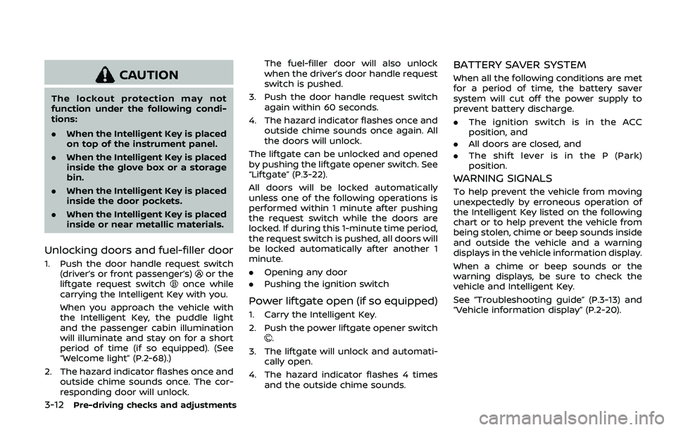
Unlocking doors and fuel-filler door
1. Push the door handle request switch
(driver’s or front passenger’s)or the
liftgate request switchonce while
carrying the Intelligent Key with you.
When you approach the vehicle with
the Intelligent Key, the puddle light
and the passenger cabin illumination
will illuminate and stay on for a short
period of time (if so equipped). (See
“Welcome light” (P.2-68).)
2. The hazard indicator flashes once and outside chime sounds once. The cor-
responding door will unlock. The fuel-filler door will also unlock
when the driver’s door handle request
switch is pushed.
3. Push the door handle request switch again within 60 seconds.
4. The hazard indicator flashes once and outside chime sounds once again. All
the doors will unlock.
The liftgate can be unlocked and opened
by pushing the liftgate opener switch. See
“Liftgate” (P.3-22).
All doors will be locked automatically
unless one of the following operations is
performed within 1 minute after pushing
the request switch while the doors are
locked. If during this 1-minute time period,
the request switch is pushed, all doors will
be locked automatically after another 1
minute.
. Opening any door
. Pushing the ignition switch
Power liftgate open (if so equipped)
1. Carry the Intelligent Key.
2. Push the power liftgate opener switch
.
3. The liftgate will unlock and automati- cally open.
4. The hazard indicator flashes 4 times and the outside chime sounds.
BATTERY SAVER SYSTEM
When all the following conditions are met
for a period of time, the battery saver
system will cut off the power supply to
prevent battery discharge.
.The ignition switch is in the ACC
position, and
. All doors are closed, and
. The shift lever is in the P (Park)
position.
WARNING SIGNALS
To help prevent the vehicle from moving
unexpectedly by erroneous operation of
the Intelligent Key listed on the following
chart or to help prevent the vehicle from
being stolen, chime or beep sounds inside
and outside the vehicle and a warning
displays in the vehicle information display.
When a chime or beep sounds or the
warning displays, be sure to check the
vehicle and Intelligent Key.
See “Troubleshooting guide” (P.3-13) and
“Vehicle information display” (P.2-20).
Page 189 of 536
WARNING
The Intelligent Key transmits radio
waves when the buttons are pushed.
The FAA advises that radio waves
may affect aircraft navigation and
communication systems. Do not op-
erate the Intelligent Key while on an
airplane. Make sure the buttons are
not operated unintentionally when
the unit is stored for a flight.
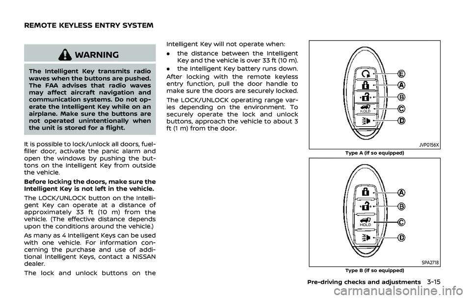
It is possible to lock/unlock all doors, fuel-
filler door, activate the panic alarm and
open the windows by pushing the but-
tons on the Intelligent Key from outside
the vehicle.
Before locking the doors, make sure the
Intelligent Key is not left in the vehicle.
The LOCK/UNLOCK button on the Intelli-
gent Key can operate at a distance of
approximately 33 ft (10 m) from the
vehicle. (The effective distance depends
upon the conditions around the vehicle.)
As many as 4 Intelligent Keys can be used
with one vehicle. For information con-
cerning the purchase and use of addi-
tional Intelligent Keys, contact a NISSAN
dealer.
The lock and unlock buttons on the Intelligent Key will not operate when:
.
the distance between the Intelligent
Key and the vehicle is over 33 ft (10 m).
. the Intelligent Key battery runs down.
After locking with the remote keyless
entry function, pull the door handle to
make sure the doors are securely locked.
The LOCK/UNLOCK operating range var-
ies depending on the environment. To
securely operate the lock and unlock
buttons, approach the vehicle to about 3
ft (1 m) from the door.
JVP0156X
Type A (if so equipped)
SPA2718Type B (if so equipped)
Pre-driving checks and adjustments3-15
REMOTE KEYLESS ENTRY SYSTEM
Page 190 of 536
3-16Pre-driving checks and adjustments
SPA1926B
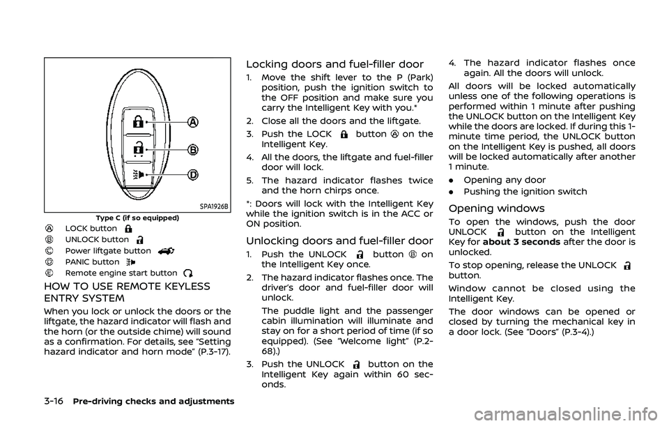
Type C (if so equipped)LOCK buttonUNLOCK buttonPower liftgate buttonPANIC buttonRemote engine start button
HOW TO USE REMOTE KEYLESS
ENTRY SYSTEM
When you lock or unlock the doors or the
liftgate, the hazard indicator will flash and
the horn (or the outside chime) will sound
as a confirmation. For details, see “Setting
hazard indicator and horn mode” (P.3-17).
Locking doors and fuel-filler door
1. Move the shift lever to the P (Park)position, push the ignition switch to
the OFF position and make sure you
carry the Intelligent Key with you.*
2. Close all the doors and the liftgate.
3. Push the LOCK
buttonon the
Intelligent Key.
4. All the doors, the liftgate and fuel-filler door will lock.
5. The hazard indicator flashes twice and the horn chirps once.
*: Doors will lock with the Intelligent Key
while the ignition switch is in the ACC or
ON position.
Unlocking doors and fuel-filler door
1. Push the UNLOCKbuttonon
the Intelligent Key once.
2. The hazard indicator flashes once. The driver’s door and fuel-filler door will
unlock.
The puddle light and the passenger
cabin illumination will illuminate and
stay on for a short period of time (if so
equipped). (See “Welcome light” (P.2-
68).)
3. Push the UNLOCK
button on the
Intelligent Key again within 60 sec-
onds. 4. The hazard indicator flashes once
again. All the doors will unlock.
All doors will be locked automatically
unless one of the following operations is
performed within 1 minute after pushing
the UNLOCK button on the Intelligent Key
while the doors are locked. If during this 1-
minute time period, the UNLOCK button
on the Intelligent Key is pushed, all doors
will be locked automatically after another
1 minute.
. Opening any door
. Pushing the ignition switch
Opening windows
To open the windows, push the door
UNLOCKbutton on the Intelligent
Key for about 3 seconds after the door is
unlocked.
To stop opening, release the UNLOCK
button.
Window cannot be closed using the
Intelligent Key.
The door windows can be opened or
closed by turning the mechanical key in
a door lock. (See “Doors” (P.3-4).)
Page 200 of 536
3-26Pre-driving checks and adjustments
CAUTION
.The liftgate will automatically
close from a partly open position.
To avoid pinching, keep hands
and fingers away from liftgate
opening.
. Do not let children operate the
liftgate.
SPA2751
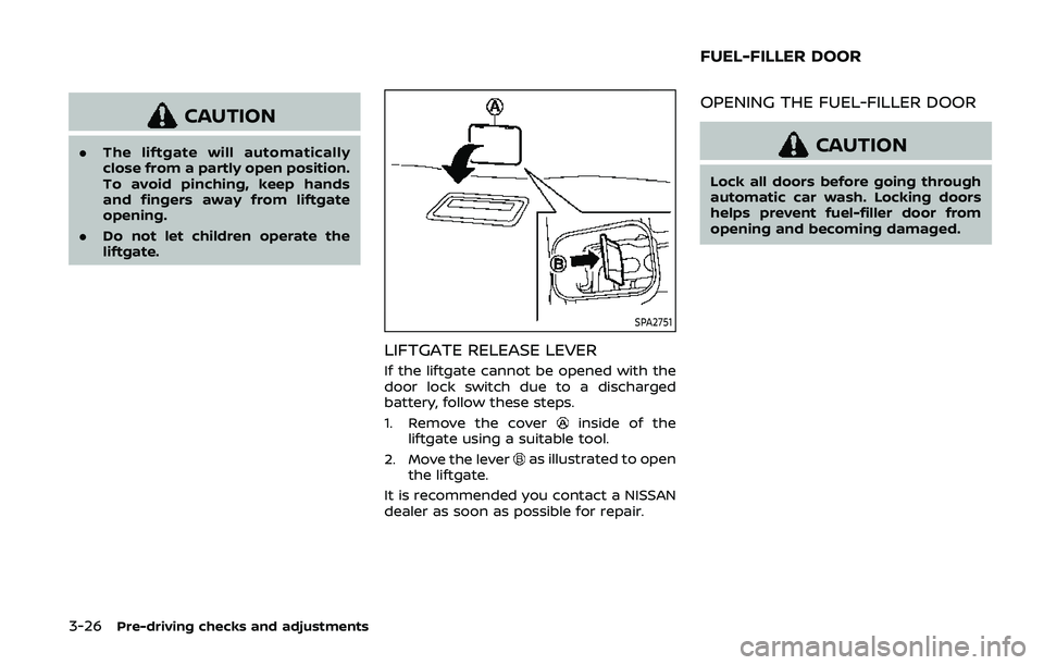
LIFTGATE RELEASE LEVER
If the liftgate cannot be opened with the
door lock switch due to a discharged
battery, follow these steps.
1. Remove the cover
inside of the
liftgate using a suitable tool.
2. Move the lever
as illustrated to open
the liftgate.
It is recommended you contact a NISSAN
dealer as soon as possible for repair.
OPENING THE FUEL-FILLER DOOR
CAUTION
Lock all doors before going through
automatic car wash. Locking doors
helps prevent fuel-filler door from
opening and becoming damaged.
FUEL-FILLER DOOR
Page 201 of 536
SPA2752
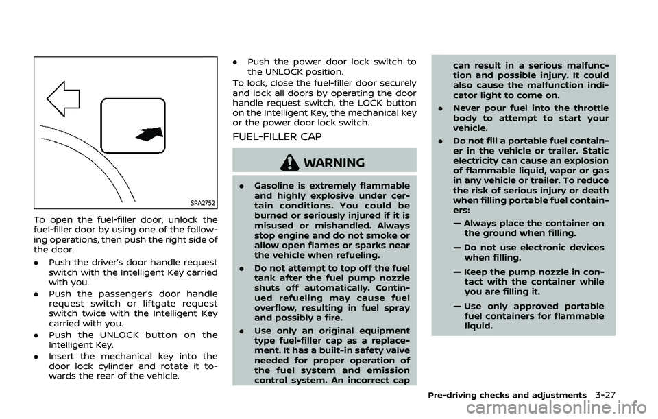
To open the fuel-filler door, unlock the
fuel-filler door by using one of the follow-
ing operations, then push the right side of
the door.
.Push the driver’s door handle request
switch with the Intelligent Key carried
with you.
. Push the passenger’s door handle
request switch or liftgate request
switch twice with the Intelligent Key
carried with you.
. Push the UNLOCK button on the
Intelligent Key.
. Insert the mechanical key into the
door lock cylinder and rotate it to-
wards the rear of the vehicle. .
Push the power door lock switch to
the UNLOCK position.
To lock, close the fuel-filler door securely
and lock all doors by operating the door
handle request switch, the LOCK button
on the Intelligent Key, the mechanical key
or the power door lock switch.
FUEL-FILLER CAP
WARNING
. Gasoline is extremely flammable
and highly explosive under cer-
tain conditions. You could be
burned or seriously injured if it is
misused or mishandled. Always
stop engine and do not smoke or
allow open flames or sparks near
the vehicle when refueling.
. Do not attempt to top off the fuel
tank after the fuel pump nozzle
shuts off automatically. Contin-
ued refueling may cause fuel
overflow, resulting in fuel spray
and possibly a fire.
. Use only an original equipment
type fuel-filler cap as a replace-
ment. It has a built-in safety valve
needed for proper operation of
the fuel system and emission
control system. An incorrect cap can result in a serious malfunc-
tion and possible injury. It could
also cause the malfunction indi-
cator light to come on.
. Never pour fuel into the throttle
body to attempt to start your
vehicle.
. Do not fill a portable fuel contain-
er in the vehicle or trailer. Static
electricity can cause an explosion
of flammable liquid, vapor or gas
in any vehicle or trailer. To reduce
the risk of serious injury or death
when filling portable fuel contain-
ers:
— Always place the container on
the ground when filling.
— Do not use electronic devices when filling.
— Keep the pump nozzle in con- tact with the container while
you are filling it.
— Use only approved portable fuel containers for flammable
liquid.
Pre-driving checks and adjustments3-27
Page 202 of 536
3-28Pre-driving checks and adjustments
CAUTION
.If fuel is spilled on the vehicle
body, flush it away with water to
avoid paint damage.
. Insert the cap straight into the
fuel-filler tube, then tighten until
the fuel-filler cap clicks. Failure to
tighten the fuel-filler cap properly
may cause the
malfunction
indicator light (MIL) to illuminate.
If the
light illuminates be-
cause the fuel-filler cap is loose
or missing, tighten or install the
cap and continue to drive the
vehicle. The
light should turn
off after a few driving trips. If the
light does not turn off after a
few driving trips, have the vehicle
inspected. It is recommended you
visit a NISSAN dealer for this
service.
. The LOOSE FUEL CAP warning will
appear if the fuel-filler cap is not
properly tightened. It may take a
few driving trips for the message
to be displayed. Failure to tighten
the fuel-filler cap properly after
the LOOSE FUEL CAP warning
appears may cause the
Mal-
function Indicator Light (MIL) to illuminate.
Turn the cap counterclockwise to re-
move. To tighten, turn the cap clockwise
until a single click is heard.
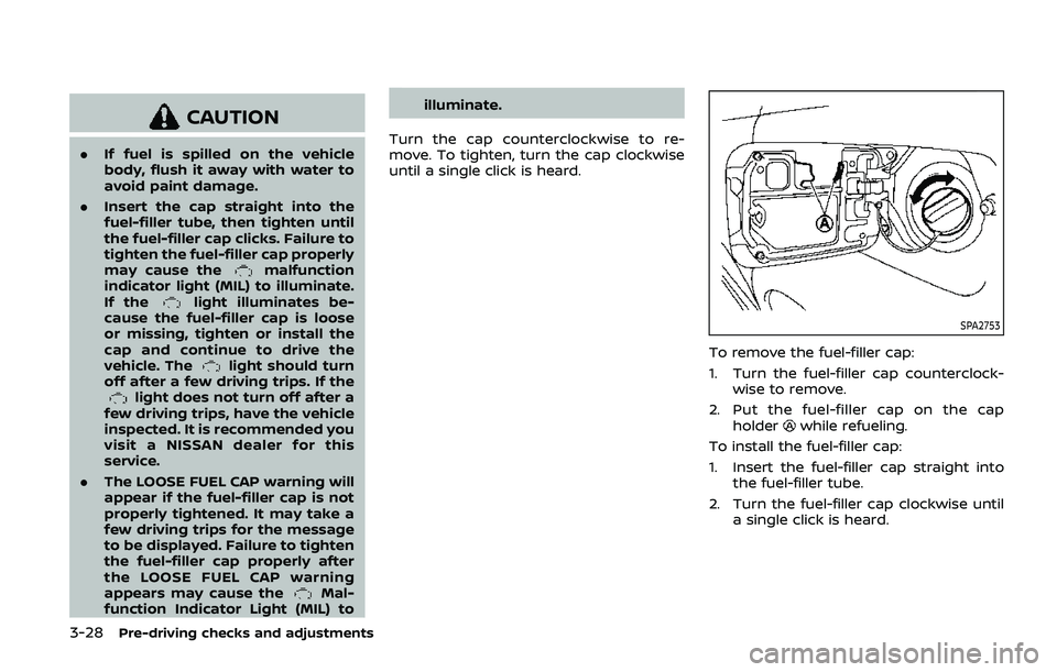
SPA2753
To remove the fuel-filler cap:
1. Turn the fuel-filler cap counterclock- wise to remove.
2. Put the fuel-filler cap on the cap holder
while refueling.
To install the fuel-filler cap:
1. Insert the fuel-filler cap straight into the fuel-filler tube.
2. Turn the fuel-filler cap clockwise until a single click is heard.
Page 203 of 536
SPA2815
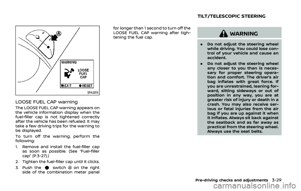
LOOSE FUEL CAP warning
The LOOSE FUEL CAP warning appears on
the vehicle information display when the
fuel-filler cap is not tightened correctly
after the vehicle has been refueled. It may
take a few driving trips for the warning to
be displayed.
To turn off the warning, perform the
following:
1. Remove and install the fuel-filler capas soon as possible. (See “Fuel-filler
cap” (P.3-27).)
2. Tighten the fuel-filler cap until it clicks.
3. Push the
switchon the right
side of the combination meter panel for longer than 1 second to turn off the
LOOSE FUEL CAP warning after tigh-
tening the fuel cap.
WARNING
.
Do not adjust the steering wheel
while driving. You could lose con-
trol of your vehicle and cause an
accident.
. Do not adjust the steering wheel
any closer to you than is neces-
sary for proper steering opera-
tion and comfort. The driver’s air
bag inflates with great force. If
you are unrestrained, leaning for-
ward, sitting sideways or out of
position in any way, you are at
greater risk of injury or death in a
crash. You may also receive ser-
ious or fatal injuries from the air
bag if you are up against it when
it inflates. Always sit back against
the seatback and as far away as
practical from the steering wheel.
Always use the seat belts.
Pre-driving checks and adjustments3-29
TILT/TELESCOPIC STEERING
Page 224 of 536
4-8Monitor, heater, air conditioner, audio, phone and voice recognition systems
screen is not displayed. Push the SETTING
button and select “Camera/Sonar” key,
and then select “Display” key.
NOTE:
Do not adjust any of the display settings
of the RearView Monitor while the
vehicle is moving. Make sure the park-
ing brake is firmly applied.
PREDICTIVE COURSE LINE SET-
TINGS
To toggle on and off the predictive course
lines:
1. Push the SETTING button while theRearView Monitor screen is not dis-
played.
2. Select “Camera/Sonar” key.
3. Select “Camera” key.
4. Select “Predictive Course Lines” key to turn the feature on or off. When this
item is turned on, the predictive
course lines will be displayed on the
monitor.
REARVIEW MONITOR SYSTEM LIM-
ITATIONS
WARNING
Listed below are the system limita-
tions for RearView Monitor. Failure to
operate the vehicle in accordance
with these system limitations could
result in serious injury or death.
.The system cannot completely
eliminate blind spots and may
not show every object.
. Underneath the bumper and the
corner areas of the bumper can-
not be viewed on the RearView
Monitor because of its monitoring
range limitation. The system will
not show small objects below the
bumper, and may not show ob-
jects close to the bumper or on
the ground.
. Objects viewed in the RearView
Monitor differ from actual dis-
tance because a wide-angle lens
is used.
. Objects in the RearView Monitor
will appear visually opposite
compared to when viewed in the
rearview and outside mirrors. .
Use the displayed lines as a re-
ference. The lines are highly af-
fected by the number of
occupants, fuel level, vehicle po-
sition, road conditions and road
grade.
. Make sure that the liftgate is
securely closed when backing up.
. Do not put anything on the rear-
view camera. The rearview cam-
era is installed above the license
plate.
. When washing the vehicle with
high-pressure water, be sure not
to spray it around the camera.
Otherwise, water may enter the
camera unit causing water con-
densation on the lens, a malfunc-
tion, fire or an electric shock.
. Do not strike the camera. It is a
precision instrument. Otherwise,
it may malfunction or cause da-
mage resulting in a fire or an
electric shock.
The following are operating limitations
and do not represent a system malfunc-
tion:
. When the temperature is extremely
high or low, the screen may not clearly
display objects.