2019 MERCEDES-BENZ GLS SUV tow bar
[x] Cancel search: tow barPage 119 of 729
Ad
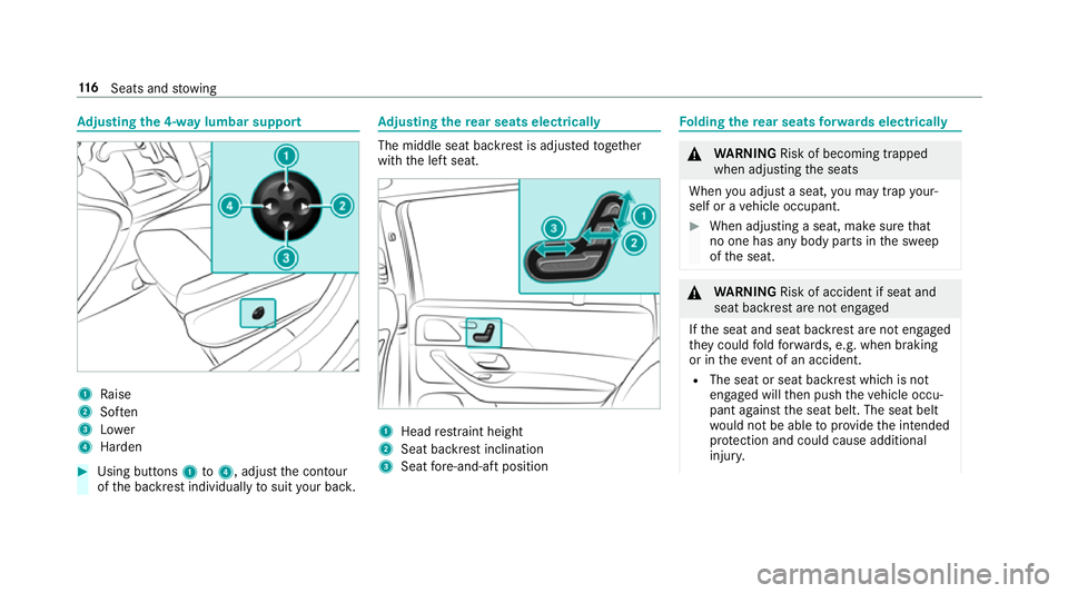
justing the 4-w aylumbar support 1
Raise
2 Soften
3 Lower
4 Harden #
Using buttons 1to4 , adjust the conto ur
of the backrest individually tosuit your bac k. Ad
justing the rear seats electrical ly The middle seat backrest is adjus
tedto ge ther
with the left seat. 1
Head restra int height
2 Seat backrest inclination
3 Seat fore -and-aft position Fo
lding there ar seats forw ards electrical ly &
WARNING Risk of becoming trapped
when adjusting the seats
When you adjust a seat, you may trap your‐
self or a vehicle occupant. #
When adjusting a seat, make sure that
no one has any body parts in the sweep
of the seat. &
WARNING Risk of accident if seat and
seat ba ckrest are not engaged
If th e seat and seat backrest are not engaged
th ey could fold forw ards, e.g. when braking
or in theev ent of an accident.
R The seat or seat backrest which is not
engaged will then push theve hicle occu‐
pant against the seat belt. The seat belt
wo uld not be able toprov ide the intended
pr otection and could cause additional
injur y. 11 6
Seats and stowing
Page 125 of 729
#
Release the middle rear seat backrest and
fo ld it forw ard slightly (/ page136). #
Pull the head restra int upwards as far as it
will go. #
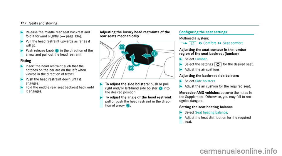
Push release knob 1inthe direction of the
ar row and pull out the head restra int.
Fi tting #
Inse rtthe head restra int such that the
notches on the bar are on the left when
vie we d in the direction of tra vel. #
Push the head restra int down until it
engages. #
Foldthe middle rear seat backrest back until
it engages. Ad
justing the luxury head restra ints of the
re ar seats mechanically #
Toadjust the side bols ters: push or pull
ri ght and/or left-hand side bols ter1 into
th e desired position. #
Toadjust the angle of the head restra int:
pull or push the head restra int in the direc‐
tion of ar row2. Configuring
the seat settings Multimedia sy
stem:
4 © 5
Comfort 5
Seat comfort
Ad justing the seat contour in the lumbar
re gion of the seat backrest (lumbar) #
Select Lumbar . #
Select the settings Zforth e desired seat. #
Adjust the air cushions.
Ad justing the backrest side bols ters #
Select Side bolsters . #
Adjust the air cushion forth ere qu ired seat.
Mercedes-AMG vehicles: observeth e no tes in
th e Supplement. Otherwise, you may failto rec‐
ognise dangers.
Setting the seat heating balance #
Select Seat heating balance. #
Adjust the heat distribution forth ere qu ired
seat. 12 2
Seats and stowing
Page 287 of 729
The
vehicle or other objects could oth‐
erwise be damaged. If
th eé symbol is shown in the multifunction
displa y,Pa rking Assist PARKTRONIC is not
active.
Multimedia sy stem:
4 Settings 5
Quick access
5 PARKTRONIC #
Activate or deacti vate the function.
% Parking Assist PARKTRONIC is automatical ly
activated when theve hicle is star ted.
Fu nction of Trailer Manoeuvring Assist
* NO
TEDama getotraile rswith a stabilisa‐
tion device against swerving In
the case of trailers with a stabilisation
device against swerving, the trailer or trailer
to w hit chcould be damaged. #
If a trailer coupling wi thTrailer Manoeu‐
vring Assist is used, on lyuse trailers without a
stabilisation device against
swerving. *
NO
TEDama gedue to ov erhanging loads
in front or dr awbar ins tallations The
vehicle and the trailer may be damaged
during manoeuvring due toove rhanging
loads at the front of the trailer or dr awbar
ins tallations. #
Pay attention to overhanging loads or
dr aw bar ins tallations while manoeu‐
vring. Tr
ailer Manoeuv ring Assi stassists you when
re ve rsing with a trailer. By means of a turning
angle sensor in the trailer coupling, Trailer
Manoeuv ring Assi stmonitors the articulation
angle between theve hicle and trailer and
adjusts it toa specified value.
Yo u can either en terth e articulation angle value
directly via the multimedia sy stem or use a
st ra ightening manoeuvre. When car rying out a
st ra ightening manoeuvre, the sy stem calculates
th e articulation angle automatically and stra ight‐ ens
theve hicle/trailer combination tothe trail‐
er's cur rent di rection.
Tr ailer Manoeuv ring Assi stmust be taught-in
before it can adjust the articulation angle
(/ page 284).
Obser vethe no tes on towing a trailer
(/ page 311).
Sy stem limitations
The sy stem may be impaired or may not function
in thefo llowing situations:
R The gradient is more than appr oximately
15 %.
Using Trailer Manoeuvring Assist
Re quirements:
R The ignition and engine are on and theve hi‐
cle is operational.
R A trailer has been de tected. 284
Driving and pa rking
Page 321 of 729
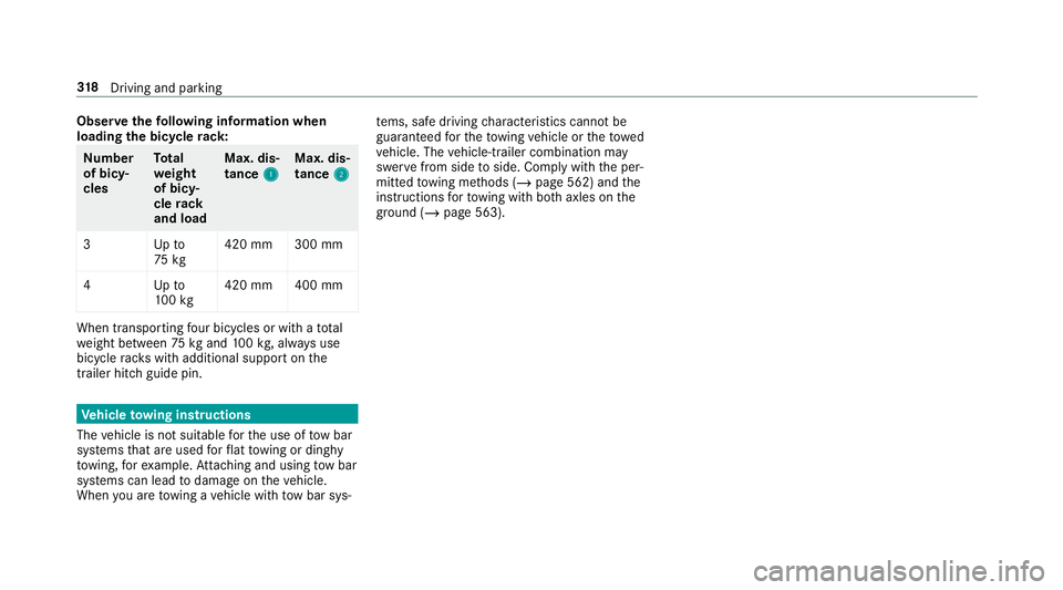
Obser
vethefo llowing information when
loading the bicycle rack: Nu
mber
of bicy‐
cles To
tal
we ight
of bicy‐
cle rack
and load Max. dis‐
tance
1 1Max. dis‐
tance
2 2
3U pto
75 kg 420 mm 300 mm
4U pto
10 0kg 420 mm 400 mm When transpo
rting four bic ycles or with a total
we ight between 75kgand 100kg , alw ays use
bicycle rack s with additional support on the
trailer hitch guide pin. Ve
hicle towing instructions
The vehicle is not suitable forth e use of tow bar
sy stems that are used forflat towing or ding hy
to wing, forex ample. Attach ing and using tow bar
sy stems can lead todamage on theve hicle.
When you are towing a vehicle with tow bar sys‐ te
ms, safe driving characteristics cannot be
guaranteed forth eto wing vehicle or theto wed
ve hicle. The vehicle-trailer combination may
swer vefrom side toside. Comply with the per‐
mitted towing me thods (/ page 562) and the
instructions forto wing with bo thaxles on the
ground ( /page 563). 318
Driving and pa rking
Page 489 of 729
Processing of personal data via
the11 2
emer gency call sy stem (EU eCall)
All processing of personal data via the11 2 emer‐
ge ncy call sy stem (EU eCall) cor responds with
th e specifications in the EU Regulation 20 16/79
"on the pr otection of individuals with rega rd to
th e processing of personal data (GDPR)" and is
based particular lyon the necessity of upholding
th e vital interests of the af fected person in
acco rdance with Article 6, Clause 1,Letter d of
th e GDPR.
The processing of this type of data is strictly
limited tothe purpose of operating the emer‐
ge ncy calls tothest andard European emer gency
call number 112.
Data recipient
The recipients of da tathat is processed using
th e11 2 emergency call sy stem (EU eCall) are the
re leva nt eme rgency call inquiry term inals that
are specified tofirs tre cei veand handle emer‐
ge ncy calls tothest andard European emer gency
call number 112by there spective country
authorities in whose territory you are located. Ar
rangements for data processing
Bo th emer gency call sy stems are designed so
th at thefo llowing requ irements are fulfilled:
R The data con tained in the sy stem memory is
not accessible outside the sy stem prior to
th e initiation of an emer gency call.
R Both emer gency call sy stems cann otbe
traced and there is no continuous tracking in
normal operation.
R The data in the sy stem's internal memory is
automatically and continuously dele ted.
R The location data of theve hicle is continu‐
ously overwritten in the sy stem's internal
memor y,so that no more than the last three
cur rent locations requ ired forth e normal
function of the sy stem are available.
R The record of the activity data of bo themer‐
ge ncy call sy stems is only kept for as long as
is requ ired tofulfil the purpose of handling
th e emer gency call, and under no circum‐
st ances for more than 13 hours af terthe
time that an emer gency call is initia ted. Rights of persons af
fected bythe data pro‐
cessing
The person af fected bythe data processing (the
ve hicle owner) has theright toaccess the data
and if applicable can demand the cor rection,
del etion or bar ring of da tathat af fects him or
her and that the processing of which does not
cor respond with the GDPR regulations. Each cor‐
re ction, del etion or bar ring car ried out according
to this regulation must be shared with theth ird
party towhich the data has been transmit ted,
pr ov ided this does not pr oveto be infeasible and
does not incur disproportionate expenditure.
The person af fected bythe data processing has
th eright tocomplain tothe appropriate data
pr otection authority should they be of the opin‐
ion that their rights ha vebeen infringed bythe
processing of their personal data.
Re sponsible contact point forth e processing of
access rights: Authorised company representa‐
tive for data pr otection, Daimler AG, HPC G353,
D-70546 Stutt gart, Germany 486
MBUX multimedia sy stem
Page 559 of 729
#
Therefore, place thefilling hose in the
plastic bag that con tained the TIREFIT
kit. +
ENVIRONMEN
TALNO TEEnvironmental
pollution caused byenvironmen tally ir re‐
sponsible disposal Ty
re sealant contains polluta nts.#
Have the tyre sealant bottle disposed of
professionall y,e.g. at a Mercedes-Benz
Service Centre. #
Stow th e tyre sealant bottle, the tyre inflation
compressor and thewa rning triangle. #
Pull away immediatel y. #
Stop driving af ter appro ximately ten minu tes
and check the tyre pressure using the tyre
inflation compressor.
The tyre pressure must now be at least
13 0 kPa (1.3 bar/19 psi). &
WARNING Risk of accident due tothe
specified tyre pressure not being ach‐
ie ved
If th e specified tyre pressure is not achie ved
af te r a brief drive, the tyre is too badly dam‐
aged. The tyre sealant cannot repair the tyre
in this ins tance.
Dama ged tyres and a tyre pressure that is
to o low can significantly impair braking and
handling characteristics. #
Do not drive on. #
Consult a qualified specialist workshop. Countries
that ha veMercedes-Benz
Service24h: you will find a sticke r with thete le‐
phone number, e.g. on the B‑pillar on the driver's
side. #
Cor rect the tyre pressure if it is still at least
13 0 kPa (1.3 bar/19 psi). See the tyre pres‐
sure table on the fuel filler flap forva lues. #
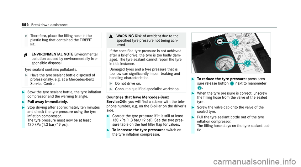
Toincrease the ty repressure: switch on
th e tyre inflation compressor. #
Toreduce the tyre pressure: press pres‐
su re re lease button 1next tomanome ter
2 . #
When the tyre pressure is cor rect, unscr ew
th efilling hose from theva lve of the sealed
tyre. #
Screw theva lve cap onto theva lve of the
sealed tyre. #
Pull the tyre sealant bottle out of the tyre
inflation compressor.
The filling hose stay s on the tyre sealant bot‐
tle. 556
Breakdown assis tance
Page 565 of 729
te
ry. Begin ea chtime wi th the conta cts on
yo ur ow nve hicle firs t. #
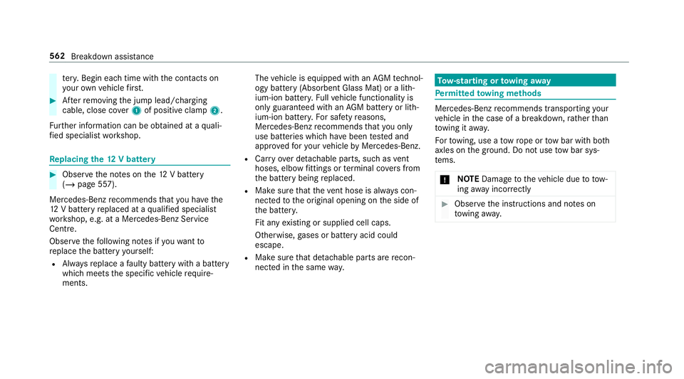
Afterre moving the jump lead/charging
cable, close co ver1 of positive clamp 2.
Fu rther information can be obtained at a quali‐
fi ed specialist workshop. Re
placing the 12V battery #
Obser vethe no tes on the12 V battery
(/ page 557).
Mercedes-Benz recommends that you ha vethe
12 V battery replaced at a qualified specialist
wo rkshop, e.g. at a Mercedes-Benz Service
Centre.
Obser vethefo llowing no tes if youwa ntto
re place the battery yourself:
R Alw aysre place a faulty bat tery with a battery
which meets the specific vehicle require‐
ments. The
vehicle is equipped with an AGMtech nol‐
ogy battery (Absorbent Glass Mat) or a li th‐
ium-ion batter y.Fu llve hicle functionality is
only guaranteed with an AGM battery or lith‐
ium-ion batter y.Fo r saf etyre asons,
Mercedes-Benz recommends that you on ly
use bat teries which ha vebeen tested and
appr ovedfo ryo ur vehicle byMercedes-Benz.
R Carryove r de tach able parts, such as vent
hoses, elbow fittings or term inal co vers from
th e battery being replaced.
R Make sure that theve nt hose is al ways con‐
nected tothe original opening on the side of
th e batter y.
Fit any existing or supplied cell caps.
Otherwise, gases or battery acid could
escape.
R Make sure that de tach able parts are recon‐
nected in the same way. To
w- starting or towing away Pe
rm itted towing me thods Mercedes-Benz
recommends transporting your
ve hicle in the case of a breakdown, rath er than
to wing it away.
Fo rto wing, use a tow rope or tow bar with bo th
axles on the ground. Do not use tow bar sys‐
te ms.
* NO
TEDama getotheve hicle due to tow‐
ing away incor rectly #
Obser vethe instructions and no tes on
to wing away. 562
Breakdown assis tance
Page 567 of 729
#
If ano ther vehicle is tow- star ted or
to we daw ay, its weight must not exceed
th e permissible gross mass of your own
ve hicle. #
Information on the permissible gross mass of
th eve hicle can be found on theve hicle iden‐
tification plate (/ page 595).#
Do not open the driver's door or front
passenger door, otherwise the automatic
transmission automatically shifts toposition
j. #
Fittheto wing eye (/ page 566). #
Fasten theto w bar.
* NO
TEDama gedue toincor rect connec‐
tion of theto w bar #
Onlyconnect theto w rope or tow bar to
th eto wing eyes. %
You can also attach theto w bar tothe trailer
hitch. #
Deactivate the automatic locking mechanism
(/ page 90). #
Do not activate the HOLD function. #
Deactivate theto w- aw ay protection
(/ page 110). #
Deactivate Active Brake Assi st (/ page 241). #
Shift the automatic transmission toposition
i. #
Release the electric parking brake. &
WARNING Risk of accident due tolimi‐
te d saf ety-re lated functions during the
to wing process
Saf ety-re lated functions are limited or no lon‐
ge rav ailable in thefo llowing situations:
R the ignition is switched off.
R the brake sy stem or po werst eering sys‐
te m is malfunctioning.
R the energy supply or the on-board electri‐
cal sy stem is malfunctioning. When
your vehicle is then towe daw ay, signif‐
icantly more ef fort may be requ ired tosteer
and brake than is no rmally requ ired. #
Use a tow bar. #
Make sure that thesteering wheel can
mo vefreely, before towing theve hicle
aw ay. *
NO
TEDama gedue toexcessive tracti ve
po wer If
yo u pull away sharpl y,the tractive po wer
may be too high and theve hicles could be
damaged. #
Pull away slowly and smoo thly. Loading the
vehicle for transport #
Obser vethe no tes on towing away
( / page 563). #
Connect theto w bar totheto wing eye in
order toload theve hicle. 564
Breakdown assis tance